Hangar 9 HAN4770 Owner's manual
- Category
- Remote controlled toys
- Type
- Owner's manual
Page is loading ...

2
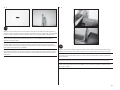
SAFETY WARNINGS AND PRECAUTIONS
Read and follow all instructions and safety precautions
before use. Improper use can result in fi re, serious injury and
damage to property.
Components
Use only with compatible components. Should any
compatibility questions exist, please refer to the product
instructions, component instructions or contact the
appropriate Horizon Hobby offi ce.
Flight
Fly only in open areas to ensure safety. It is recommended
fl ying be done at radio control fl ying fi elds. Consult local
ordinances before choosing a fl ying location.
Propeller
Keep loose items that can become entangled in the propeller
away from the prop. This includes loose clothing or other
objects such as pencils and screwdrivers. Keep your hands
away from the propeller as injury can occur.
Batteries
Always follow the manufacturer’s instructions when using
and disposing of any batteries. Mishandling of Li-Po
batteries can result in fi re causing serious injury and
damage.
Small Parts
This kit includes small parts and should not be left
unattended near children as choking and serious injury could
result.
SAFE OPERATING RECOMMENDATIONS
• Inspect your model before every fl ight to ensure it is
airworthy.
• Be aware of any other radio frequency user who may
present an interference problem.
• Always be courteous and respectful of other users in your
selected fl ight area.
• Choose an area clear of obstacles and large enough to
safely accomodate your fl ying activity.
• Make sure this area is clear of friends and spectators
prior to launching your aircraft.
• Be aware of other activities in the vicinity of your fl ight
path that could cause potential confl ict.
• Carefully plan your fl ight path prior to launch.
• Abide by any and all established AMA National Model
Aircraft Safety Code.
NOTICE
All instructions, warranties and other collateral documents are subject to change at the sole discretion of
Horizon Hobby, LLC. For up-to-date product literature, visit horizonhobby. com and click on the support tab for
this product.
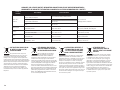
Meaning of Special Language
The following terms are used throughout the product literature to indicate various levels of potential harm
when operating this product:
NOTICE: Procedures, which if not properly followed, create a possibility of physical property damage AND a
little or no possibility of injury.
CAUTION: Procedures, which if not properly followed, create the probability of physical property damage
AND a possibility of serious injury.
WARNING: Procedures, which if not properly followed, create the probability of property damage, collateral
damage, and serious injury OR create a high probability of superfi cial injury.
WARNING: Read the ENTIRE instruction manual to become familiar with the features of the product
before operating. Failure to operate the product correctly can result in damage to the product, personal
property and cause serious injury.
This is a sophisticated hobby product. It must be operated with caution and common sense and requires
some basic mechanical ability. Failure to operate this Product in a safe and responsible manner could result
in injury or damage to the product or other property. This product is not intended for use by children without
direct adult supervision. Do not use with incompatible components or alter this product in any way outside
of the instructions provided by Horizon Hobby, LLC. This manual contains instructions for safety, operation
and maintenance. It is essential to read and follow all the instructions and warnings in the manual, prior to
assembly, setup or use, in order to operate correctly and avoid damage or serious injury.
Age Recommendation: Not for children under 14 years. This is not a toy.
USING THE MANUAL
This manual is divided into sections to help make assembly easier to understand. Boxes () have been placed
next to each step. These help keep track of steps that have been completed.
Page is loading ...
Page is loading ...
Page is loading ...

6
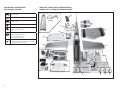
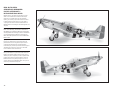
89.0 in (226 cm)
1420 sq in (91.6 dm2) Total/Totale
77.5 in (197 cm)
25.0–27.0 lb (11.3–12.2 kg)
2-Stroke Gas/2-Takt Benziner/
2 temps Essence/2-Tempi Gas
60cc
8-channel (or greater) with 10 servos
8-Kanal (oder mehr) mit 10 servos
8 voies (ou plus) avec 10 servos
A 8 canali (o più) con 10 servo
Spinner/Spinner/Cône/Ogiva dell’elica
5
1
/
2
-inch (140 mm) (not included/nicht im Lieferumfang
enthalten/non inclus/non inclusa)
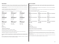
SPECIFICATIONS•SPEZIFIKATIONEN•
SPÉCIFICATIONS•SPECIFICHE
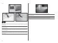
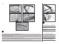
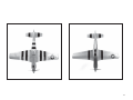
LARGE PARTS LAYOUT•BAUTEILE (OHNE KLEINTEILE)•
GRANDES PIÈCES•SCHEMA DEI COMPONENTI GRANDI
1
1, 12
10
3
2
4
5
6
7
1, 8
1,8
16
2
3
9
14
15
10
23 4
4, 11
12
13

7
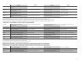
REPLACEMENT PARTS•ERSATZTEILE•PIÈCES DE RECHANGE• PEZZI DI RICAMBIO
English Deutsch Français Italiano
1. HAN477001 Fuselage Rumpf Fuselage Fusoliera
2. HAN477002 Right Wing with Aileron and Flap Tragfl äche Rechts mit Querruder und Klappe Aile droite avec aileron et volet Semiala destra con alettone e fl ap
3. HAN477003 Left Wing with Aileron and Flap Tragfl äche Links mit Querruder und Klappe Aile gauche avec aileron et volet Semiala sinistra con alettone e fl ap
4. HAN477004 Center Wing with Flap and Gear Doors Tragfl ächenmittelstück m. Klappen u. FW.-Türen Section centrale de l’aile avec trappes de train Pianetto centrale con fl ap e portelli carrello
5. HAN477005 Left and Right Stabilizers and Elevators Höhenruderset Set Plan horizontal et Gouverne de profondeur Set stabilizzatore ed elevatore
6. HAN477006 Rudder Seitenleitwerk Gouverne de direction Timone
7. HAN477007 Canopy Kabinenhaube Verrière Calotta
8. HAN477008 Cowling Motorhaube Capot moteur Carenatura
9. HAN477010 Wing and Stabilizer Tubes Flächen- und Leitwerksverbinder Clé d’aile et de stabilisateur Tubi ala e stabilizzatore
10. HAN477013 Plastic Scale Parts Kunststoff Scaleteile Pièces maquettes plastique Parti in plastica riproduzione
11. HAN477014 Gear Doors FW-Türen u. Flächenhutzen Trappes de train Portelli carrello
12. HAN477015 Wing Pylons Tragfl .-Pylone Pylônes d’ailes Piloni ala
13. HAN477016 Wood Parts Holzteile Pièces bois Parti in legno
14. HAN477019 Painted Cockpit Kit Cockpit lackiert Kit d’intérieur de cockpit peint Kit abitacolo verniciato
15. HAN477022 Fuel Tank Kraftstofftank Réservoir à carburant Serbatoio carburante
16. HAN477023 Engine Mount Standoff Motordistanzstücke Entretoises de support moteur Supporto motore
SMALL PARTS (NOT SHOWN)•KLEINTEILE (NICHT ABGEBILDET)•PETITES PIÈCES (NON REPRÉSENTÉES)•PARTI DI PICCOLE DIMENSIONI (NON MOSTRATE)
HAN477011 Hardware Pack Kleinteilepaket Sachet d’accessoires Viti e accessori
HAN477012 Pushrod Set Gestänge / Anlenkungen Set Jeu de tringleries Set dell’asta di spinta
HAN477017 Decal Set Dekorbogen Planche de décoration Set di decalcomanie
OPTIONAL ITEMS•OPTIONALE TEILE•ELÉMENTS OPTIONNELS•ARTICOLI OPZIONALI
HAN477020 Painted Aluminum Spinner Aluminiumspinner lackiert Cône en aluminium peint Ogiva in alluminio verniciata
HAN477021 Dummy Drop Tanks Abwurftankattrappen Faux réservoirs largables Serbatoi fi nti sganciabili
HAN476017 Bombs: F4U-1D Corsair 60cc Bombenattrappen Bombes - F4U-1D corsair Bombe: F4U-1D Corsair 60cc
WWII Pilot 15-in size is available from Ein WWII Pilot in 15 inch Größe ist bei Le pilote seconde guerre mondiale est disponible sur Il pilota della II guerra mondiale da 38cm è
www.warbirdpilots.com www.warbirdpilots.com erhältlich www.warbirdpilots.com disponibile da www.warbirdpilots.com

8
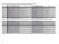
REQUIRED RADIO EQUIPMENT (NOT INCLUDED)•ERFORDERLICHE RC AUSRÜSTUNG (NICHT IM LIEFERUMFANG)•
EQUIPEMENT RADIO REQUIS (NON FOURNIS)•APPARECCHIATURE RADIO (NON COMPRESO)
English Deutsch Français Italiano
SPMAR9110 AR9110 9-Channel DSMX
®
PowerSafe
™
Receiver AR9110 9-Kanal DSMX PowerSafe-Empfänger Récepteur DSMX PowerSafe 9 voies AR9110 Ricevitore AR9110 DSMX PowerSafe a 9 canali
SPMB2200LFRX (2) 2200mAh 2S 6.6V LiFe Rx Battery 2200mAh 2S 6.6V LiFe Empfänger Akku Batterie RX Li-Fe 2S 6.6V 2200mA Batteria RX 2200mAh 2S 6.6V LiFe
SPMEXEC324 (2) 24-Inch EC3
™
Extension with 16AWG Spektrum 60cm EC3 Verlängerung 16AWG Rallonge EC3 long. 60cm Prolunga EC3 60cm 16AWG
SPMSA6180 A6180 Digital Aircraft Servo (Rudder) Spektrum A6180 Digital Flug -Servo Servo numérique A6180 pour aéronefs Servo digitale A6180 per aeromodelli
SPMSA6150 (2) (3*) A6150 HV High Torque Waterproof Metal Gear Servo Spektrum A6150 HV High Torque Servo Servo A6150 HV, couple élevé, pignons métal, A6150 HV servo con ingran. metallici alta coppia
Rudder servo, Flap servos m. Metallgetriebe étanche pour dérive et volets Servo timone, servi fl ap
SPMSA5060 (2) A5060 Mini HV Digital Hi-Torque MG Aircraft Servo Spektrum Mini HV Digital Hi-Torque Mini servo A5060 HV digital, A5060 HV servo digitale alta coppia MG per aereo
Elevator servos Metallgetriebe Höhenruderservo couple élevé, pignons métal, pour la profondeur Servi elevatore
SPMSA6220 (2) A6220 HV Dig Low-Profi le Hi-Torque MG Aircraft SX Spektrum A6220 HV Dig Low-Profi le Hi-Torque Servo profi l bas A6220 HV digital, couple élevé, A6220 HV servo dig. basso profi lo alta coppia MG
Aileron servos Metallgetriebe Querruderservos pignons métal, pour ailerons Servi alettoni
SPMSA6110 A6110 HV Standard Servo Spektrum A6110 HV Gasservo Servo A6110 HV, pour les gaz A6110 HV servo standard
Throttle servo Servo motore
SPMSA7040 (2) A7040 HV Retract Servo Spektrum A7040 HV Fahrwerkstürservo Servo A7040 HV, pour les portes du train rentrant A7040 HV servo per retrattili
Main gear door servos Servi per portelli carrello
JRPA215 (2) HD Servo Arms (Rudder and Flap) HD Servo Arms (Rudder and Flap) Bras de servo renforcés (Dérive et volets) HD squadrette servo (timone e fl ap)
HAN9154 (2) Aluminum Sx Arm, 1.5-inch (Main Gear Doors) Hangar 9 Aluminum Servo Arm, 1.5 JR Bras de servos en aluminium, 38mm Squadretta servo allum. 38mm (portelli carrello)
(Trappes de train rentrant)
SPMA4021 Hook and Loop Fastening Strap: 20x430mm Spektrum Klettband , 20x430mm Sangle auto-agrippante 20x430mm, Fascetta a strappo: 20x430mm x fi ssaggio serbatoio
Fuel tank pour réservoir à carburant
SPMA4020 Hook and Loop Fastening Strap: 20 x 280mm Spektrum Klettband, 20x280mm Sangle auto-agrippante 20x280mm, Fascetta a strappo: 20x430mm x fi ssaggio
Receiver battery pour batterie de réception batt. ricevitore
SPMA3000 (4) 3-inch Heavy-Duty Servo Extension Servokabelverlängerung 75 mm (3 inch) Rallonge de servo, 75 mm Estensione servo 3 pollici
Receiver (ailerons, fl aps, retracts) Récepteur (Ailerons, volets, train rentrant) Ricevitore (alettoni, fl aps, carrelli retr.)
SPMA3001 (5) 6-inch Heavy-Duty Servo Extension Servokabelverlängerung 150 mm (6 inch) Rallonge de servo, 150 mm Estensione servo 6 pollici
Aileron tip panels, fl aps center section, receiver switch Ailerons d’extrémités, volets de la section centrale, Pannelli estremità alettoni, fl ap sezione centrale,
interrupteur RX interr. ricevitore
HAN3615 10-32 Swivel Clevis Horn (2) Hangar 9 Schwenkruderanlenkung (2) Chapes articulées (2) 10-32 parte girevole cerniera (2)

9
English Deutsch Français Italiano
SPMA3001 6-inch Heavy-Duty Servo Extension Servokabelverlängerung 150 mm (6 inch) Rallonge de servo, 150 mm Estensione servo 6 pollici
Throttle servo servo x motore
SPMA3004 (2) 18-inch Heavy-Duty Servo Extension Servokabelverlängerung 460 mm (18 inch) Rallonge de servo, 460 mm Estensione servo 18 pollici
Remote charge jack Jack remoto per la carica
SPMA3005 (2) 24-inch Heavy-Duty Servo Extension Servokabelverlängerung 600 mm (24 inch) Rallonge de servo, 600 mm Estensione servo 24 pollici
Aileron center section Alettoni sezione centrale
SPMA3006 (2) 36-inch Heavy-Duty Servo Extension Servokabelverlängerung 920 mm (36 inch) Rallonge de servo, 920 mm Estensione servo 36 pollici
Elevators Elevatori
* When using a high voltage (HV) battery set-up, subsitute SPMSA6150 for the rudder servo. The opening for the rudder servo will then require modifi cation to increase the length of the opening 3/32 inch (2mm).
* Bei einer HV High Volt Akkuversorgung setzen Sie für das Seitenruder das SPMSA6150 Servo ein. Die Servoöffnung muß dabei um 2mm Länge vergrößert werden.
* Quand vous utilisez une batterie HV, installez un servo SPMSA6150 à la dérive. Le logement prévu pour le servo de dérive devra être allongé de 2mm dans le sens de la longueur.
* Quando si usa un impianto con batteria ad alta tensione (HV) sostituire SPMSA6150 per il servo del timone. L’apertura per il servo del timone deve essere aumentata di 2mm.
2-STROKE GAS•2-TAKT BENZINER•2 TEMPS ESSENCE•2-TEMPI A BENZINA
EVOE62GXI 62GXi 62cc Single Cylinder Gas Engine Evolution 62cc Zylinder Benzinmotor mit EFI Moteur 62GXi mono-cylindre essence 62cc 62GXi 62cc Motore a benzina monocilindrico
with SureFire
™
EFI avec injection SureFire EFI con SureFire EFI
EVOM14* (Optional) Wrap Around Muffl er 62cc Modifi ed Wrap Around Muffl er 62cc Modifi ed Silencieux compact modifi é pour 62cc Silenziatore avvolgente 62cc modifi cato
22 x 8 or 24-10 Propeller 22 x 8 or 24-10 Propeller Hélice 22 x 8 or 24-10 22 x 8 or 24-10 Elica
SPMB1450LFRX 1450mAh 2S 6.6V LiFe Rx Battery Spektrum 1450mAh 2S 6.6V Li-Fe Empfängerakku Batterie RX Li-Fe 2S 6.6V 1450mA Batteria Rx 1450mAh 2S 6.6V LiFe
EVOA112 Evolution
®
3 Wire Ignition/Receiver Switch Evolution Zündschalter Interrupteur Evolution Allumage/RX Interruttore accensione/ricevitore Evolution 3 fi li
HAN116 Fuel Filler with “T” and Overfl ow Fittings Tanknippel mit T-Stück u. Überlauf Fitting Remplissage carburant avec raccords en Riempitore carburante con “T” e raccordi troppo pieno
« T » et de débordement
EVOA103 Medium Gas-FKM Fuel Tubing (3 Meters) Medium Viton Kraftstoffschlauch (3 Meter) Durite FKM pour essence, diamètre moyen (3 mètres) Tubetto medio FKM per benzina (3 metri)
* The optional wrap around muffl er will fi t into the cowling without the need to trim the cowling.
* Der optionale Einbauschalldämpfer passt ohne Änderungen unter die Motorhaube.
* Le silencieux intégré optionnel se loge à l’intérieur du capot sans devoir découper des ouvertures.
* Il silenziatore speciale opzionale entra nella capottina motore senza dover fare modifi che.
REQUIRED ELECTRIC RETRACTS (NOT INCLUDED)•ELEKTRISCHES EINZIEHFAHRWERK (NICHT IM LIEFERUMFANG)•
TRAIN RENTRANT ÉLECTRIQUE REQUIS (NON FOURNI)•CARRELLI RETRATTILI ELETTRICI NECESSARI (NON INCLUSI)
HAN477018 (2) 5
1
/
4
inch P-51D Mustang Wheel Hangar 9 P-51D Mustang 60cc: Hauptfahrwerksreifen Roues 5
1
/
4
˝ pour P-51D Ruota 130mm P-51D Mustang
EFLG700 90 degree P-51D Mustang Main Retracts E-fl ite 50-60cc 90° EZFW P-51 Train rentrant principal 90° pour P-51D Carrello retrattile principale 90 gradi P-51D
EFLG750 90 degree P-51D Mustang Tail Wheel Retract E-fl ite 50-60cc 90° EZ-Spornrad P-51 Roulette de queue rétractable pour P-51D Carrello retrattile di coda 90 gradi P-51D

10
OPTIONAL PAYLOAD RELEASE (NOT INCLUDED)•OPTIONALES NUTZLASTABWURFSYSTEM (NICHT IM LIEFERUMFANG)•
DISPOSITIF DE LARGAGE OPTIONNEL (NON FOURNIS)•SGANCIO CARICHI OPZIONALE (NON COMPRESO)
English Deutsch Français Italiano
EFLA405 (2) Servoless Payload Release E-fl ite Servoloses Nutzlastabwurfsystem Dispositif de largage sans servo Sgancio carichi senza servo
SPMA3001 Heavy-Duty Servo Extension 6 inch Servokabelverlängerung 150 mm Rallonge de servo 150 mm Prolunga servo HD 150 mm
Receiver Empfänger Récepteur Ricevitore
SPMA3002 Heavy-Duty Servo Extension 9 inch Servokabelverlängerung 230 mm Rallonge de servo 230 mm Prolunga servo HD 230 mm
Release Mechanism Auslösemechanismus Mécanisme de largage Meccanismo di rilascio
SPMA3005 Heavy-Duty Servo Extension 24 inch Servokabelverlängerung 600 mm Rallonge de servo 600 mm Prolunga servo HD 600 mm
Wing center section Tragfl ächenmittelteil Section centrale de l’aile Sezione centrale ala
SPMA3006 Heavy-Duty Servo Extension 36 inch Servokabelverlängerung 920 mm Rallonge de servo 920 mm Prolunga servo HD 920 mm
Wing center section Tragfl ächenmittelteil Section centrale de l’aile Sezione centrale ala
HAN476017 Bombs: F4U-1D Corsair 60cc Hangar 9 F4U-1D Corsair 60cc ARF : Bomben Bombes - F4U-1D Corsaire 60cc Bombe: F4U-1D Corsair 60cc
EFLA406 Servoless Payload Release Mounting Plate (2) E-fl ite elektrisches Entriegelungssytem: Crochet de charge pour dispositif de largage (2) Piastra montaggio rilascio carichi paganti
Adapterplatten (2) senza servo (2)
OPTIONAL LIGHTING (NOT INCLUDED)•OPTIONALE BELEUCHTUNG (NICHT IM LIEFERUMFANG)•ECLAIRAGE OPTIONNEL (NON FOURNIS)•LUCI OPZIONALI (NON COMPRESO)
EFLA600 Controller: Universal Lighting Kit Controller: Universal Beleuchtungs Kit Contrôleur: Kit d’éclairage universel Controller: Kit illuminazione universale
SPMVR5203 VR5203 Dual Output Regulator (if required) Spektrum Dual Spannungswandler (falls erforderlich) Régulateur à sortie double VR5203 (si nécessaire) Regolatore a doppia uscita VR5203 (se necessario)
EFLA601 Solid Red LED Rote LED leuchtend DEL rouge fi xe LED rosso fi sso
EFLA602 Solid Clear LED Klare LED leuchtend DEL blanche fi xe LED bianco fi sso
EFLA604 Solid Green LED Grüne LED leuchtend Universal Beleuchtungs Kit DEL verte fi xe LED verde fi sso
EFLA620 (2) 36-inch Lighting Extension Verlängerung 920mm: Universal Beleuchtungs Kit Extension d’éclairage (920mm) Prolunghe per luci da 920mm
Tip panel Panneaux d’ailes Pannello estremità
EFLA619 (2) 24-inch Lighting Extension Verlängerung 600mm: Universal Beleuchtungs Kit Extension d’éclairage (600mm) Prolunghe per luci da 600mm
Wing center section (2), rudder (2) Section centrale de l’aile (2), dérive (2) Sezione centrale ala (2), timone (2)
SPMA3050 3-inch Servo Extension Servokabelverlängerung 3 inch (75mm) Extension de servo (75mm) Prolunga servo da 75mm
Controller to receiver Entre le contrôleur et le récepteur Controller al ricevitore

11
OPTIONAL ITEMS (NOT INCLUDED)•OPTIONALE TEILE (NICHT IM LIEFERUMFANG)•ELÉMENTS OPTIONNELS (NON FOURNIS)•ARTICOLI OPZIONALI (NON COMPRESO)
English Deutsch Français Italiano
SPM9548 TM1000 DSMX Full Range Aircraft Telemetry Module Spektrum DSM Telemetriemodul TM1000 Module de télémétrie TM1000 DSMX Modulo di telemetria per aereo a piena portata
EVOA100 Optical Kill Switch optischer Killschalter Interrupteur coupe-circuit optique Interruttore ottico di spegnimento
REQUIRED ADHESIVES (NOT INCLUDED)•ERFORDERLICHE KLEBSTOFFE (NICHT IM LIEFERUMFANG)•TYPES DE COLLES (NON FOURNIS)•ADESIVI NECESSARI (NON COMPRESO)
PAAPT09 Thin CA Sekundenkleber dünnfl üssig Colle cyano fi ne Sottile CA
PAAPT03 Medium CA Sekundenkleber mittel Colle cyano moyenne Medio CA
PAAPT15 Zip Kicker Aerosol, 2 oz Zip Kicker Aerosol, 2 oz Zip Kicker, bombe aérosol, 59ml Zip Kicker Aerosol, 2 oz
PAAPT44 Rubber Toughened CA, 1 oz (28.3 g) Rubber Toughened CA, 1 oz (28.3 g) Colle ZAP RT, 28.3g Gomma indurita CA, 1 oz (28.3 g)
PAAPT12 Zap Goo, 1 oz Zap Goo, 1 oz Colle Zap GOO, 28.3g Zap Goo, 1 oz
PAAPT35 15-minute Epoxy 15 Minuten Epoxy Époxy 15 minutes Colla epoxy 15 minuti
PAAPT39 30-minute Epoxy 30 Minuten Epoxy Époxy 30 minutes Colla epoxy 30 minuti
PAAPT42 Threadlock Schraubensicherungslack Frein-filet Frenafiletti
COVERING COLORS•FOLIENFARBEN•COULEURS DE L’ENTOILAGE•COLORI RIVESTIMENTO
HANU881 Silver Silber Argent Argento
HANU874 Black Schwarz Noir Nero
HANU870 White Weiss Blanc Bianco
HANU871 Deep Red Deep Red Rouge foncé Rosso profondo
HANU904 Olive Drab Oliv Vert olive Verde oliva
HANU884 Cub Yellow Cub Gelb Jaune cub Giallo Cub

12
REQUIRED TOOLS (NOT INCLUDED)•BENÖTIGTES WERKZEUG (NICHT IM LIEFERUMFANG)•OUTILS REQUIS (NON FOURNIS)•ATTREZZI NECESSARI (NON COMPRESO)
English Deutsch Français Italiano
Black marker Faserstift Schwarz Marqueur noir Pennarello nero
Clear tape klares Klebeband Ruban adhésif transparent Nastro trasparente
Covering iron Folienbügeleisen Fer à entoiler Ferro da stiro per fi lm di copertura
Crimping tool Crimpzange Pince à sertir Pinza crimpatrice
Cuttoff wheel Trennscheibe Disque à découper Coltello rotativo
Denatured alcohol Spiritus Alcool dénaturé Alcol denaturato
Dish washing detergent Spülmittel Liquide vaisselle Detersivo per i piatti
Drill Bohrer Mini-perceuse Trapano
Drill bit: 1/16-inch, 5/64-inch, 3/32-inch, Bohrer: 1,5mm, 2mm, 2,5mm, 4,5mm, 6mm, 14,5mm Forêt: 1,5mm, 2mm, 2,5mm, 4,5mm, 6mm, 14,5mm Punte per trapano: 1,5mm, 2mm, 2,5mm, 4,5mm,
11/64-inch, 1/4-inch, 9/16-inch 6mm, 14,5mm
Felt-tipped pen Faserstift Feutre fi n effaçable Pennarello
Flat blade screwdriver: small Schraubendreher klein Petit tournevis à tête plate Cacciavite piccolo a lama piatta
Flat fi le Flachfeile Lime plate Lima piatta
Hemostat Klemme Pince Hemostat Pinzetta
Hex wrench: 1.5mm, 2mm, 2.5mm, 3mm, Inbusschlüssel: 1,5mm, 2mm, 2,5mm, 3mm, Tournevis hexagonal: 1,5mm, 2mm, 2,5mm, 3mm, Chiave esag.: 1,5mm, 2mm, 2,5mm, 3mm,
4mm, 3/16-inch 4mm, 3/16-inch 4mm, 3/16-inch 4mm, 3/16-inch
Hobby and craft square Rechteck Equerre de modélisme Riga a squadra
Hobby knife: #11 blade Hobbymesser mit # 11 Klinge Couteau : Lame numéro 11 Taglierino: #11 lama
Hobby scissors Hobbyschere Ciseaux Forbici per hobby
Hook and loop strap and tape Klettband Bande auto aggripante Nastro e fascette
Isopropyl alcohol Isopropyl Alkohol Alcool isopropylique Alcol isopropilico
Light machine oil Nähmaschinenöl Lubrifi ant Olio leggero
Low-tack tape Klebeband m. geringer Klebekraft Adhésif de masquage Nastro a bassa aderenza
Medium grit sandpaper Schleifpapier mittel Papier à poncer grain moyen Carta vetrata media
Mixing cups and sticks Mischbecher und Rührstäbchen Récipients pour mélanger et bâtons Contenitori e stick per mixer colla
Needle nose pliers Spitzzange Pince fi ne Pinze a becco stretto
Paper towels Papiertücher Papier absorbant Asciugamani di carta

13
English Deutsch Français Italiano
Pencil Stift Crayon à papier Matita
Phillips screwdriver: #0, #1, #2 Phillips Schraubendreher: #0, #1,#2 Tournevis cruciforme: #0, #1, #2 Cacciavite a croce: #0, #1, #2
Pin vise Handbohrer Porte forets Trapano manuale
Pliers Zange Pince Pinze
Propeller reamer Propellerfeile Alésoir d’hélice Alesatore per eliche
Razor saw Säge Lame de rasoir Sega Razor
Rotary tool elektrischer Handbohrer Multiutensilie Utensile rotante
Ruler Lineal Réglet Righello
Sanding drum Schleiftrommel Poncette rotative Levigatore
Scissors Schere Ciseaux Forbici
Side cutters Seitenschneider Pince coupante Lama laterale
Spray bottle Sprayfl asche Pulvérisateur Bottiglia spray
String or dental fl oss Garn / Zahnseide Ficelle ou fi l dentaire Cordino o fi lo interdentale
Toothpicks Zahnstocher Cure dents Stuzzicadenti
T-pins T- Nadeln Epingles Spilli a T
Vise grips Klemmen Pince-étau Pinze bloccanti
Wire stripper Abisolierzange Pince à dénuder Spellafi li

14
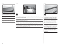
BEFORE STARTING ASSEMBLY
• Remove parts from bag.
• Inspect fuselage, wing panels, rudder and stabilizer for
damage.
• If you fi nd damaged or missing parts, contact your place
of purchase.
If you fi nd any wrinkles in the covering, use a heat gun
(HAN100) and covering glove (HAN150) or covering iron
(HAN101) with a sealing iron sock (HAN141) to remove them.
Use caution while working around areas where the colors
overlap to prevent separating the colors.
• Charge transmitter and receiver batteries.
• Center trims and sticks on your transmitter.
• For a computer radio, create a model memory for this
particular model.
• Bind your transmitter and receiver, using your radio
system’s instructions.
IMPORTANT: Rebind the radio system once all control
throws are set. This will keep the servos from moving to their
endpoints until the transmitter and receiver connect. It will
also guarantee the servo reversal settings are saved in the
radio system.
VOR DEM ZUSAMMENBAU
• Entnehmen Sie zur Überprüfung jedes Teil der Verpackung.
• Überprüfen Sie den Rumpf, Tragfl ächen, Seiten- und
Höhenruder auf Beschädigung.
• Sollten Sie beschädigte oder fehlende Teile feststellen,
kontaktieren Sie bitte den Verkäufer.
Zum Entfernen von Falten in der Bespannung verwenden
Sie den Heißluftfön (HAN100) und Bespannhandschuh
(HAN150) oder das Folienbügeleisen (HAN141). Bitte achten
Sie bei überlappenden Farben, dass Sie diese sich bei dem
Bearbeitung nicht trennen.
• Laden des Senders und Empfängers.
• Zentrieren der Trimmungen und Sticks auf dem Sender.
• Sollten Sie einen Computersender verwenden, resetten Sie
einen Speicherplatz und benennen ihn nach dem Modell.
• Sender und Empfänger jetzt nach den Bindeanweisung
des Herstellers zu binden.
WICHTIG: Wir empfehlen dringend nachdem alle
Einstellungen vorgenommen worden sind, das Modell
neu zu binden. Dieses verhindert, dass die Servos in die
Endanschläge laufen bevor sich Sender und Empfänger
verbunden haben. Es garantiert auch, dass die
Servoreverseeinstellungen in der RC Anlage gesichert sind.
AVANT DE COMMENCER L’ASSEMBLAGE
• Retirez toutes les pièces des sachets pour les inspecter.
• Inspectez soigneusement le fuselage, les ailes et les
empennages.
• Si un élément est endommagé , contactez votre revendeur.
Si l’entoilage présente quelques plis, vous pouvez les lisser
en utilisant le pistolet à air chaud (HAN100) et le gant
(HAN150) ou le fer à entoiler (HAN101) avec la chaussette
de protection (HAN141). Agissez soigneusement dans les
zone ou plusieurs couleurs d’entoilage sont superposées afi n
d’éviter de les séparer.
• ll est recommandé de préparer tous les éléments du
système de la radio.
• Cela inclus, la charge des batteries comme la mise au
neutre des trims est des manches de votre émetteur.
• Si vous utilisez une radio programmable, sélectionnez une
mémoire libre afi n d’y enregistrer les paramètres de ce
modèle.
• Nous vous recommandons d’affecter maintenant le
récepteur à l’émetteur en suivant les instructions fournies
avec votre radio.
IMPORTANT: Il est hautement recommandé de
ré-affecter le système une fois que les courses seront
réglées. Cela empêchera les servos d’aller en butée lors de
la connexion du système. Cela garantit également que la
direction des servos est enregistrée dans l’émetteur.
PRIMA DI INIZIARE IL MONTAGGIO
• Togliere tutti i pezzi dalla scatola.
• Verifi care che la fusoliera, l’ala e i piani di coda non siano
danneggiati.
• Se si trovano parti danneggiate, contattare il negozio da
cui è stato acquistato.
Se si trovano delle rughe nella ricopertura, si possono
togliere usando una pistola ad aria calda (HAN100) e guanto
per ricopertura (HAN150), oppure un ferro per ricopertura
(HAN101) con la sua calza di protezione (HAN141). Usare
cautela quando si lavora in aree del rivestimento dove ci
sono dei colori sovrapposti, per evitare la loro separazione.
• Caricare il trasmettitore e la batteria di volo.
• Centrare stick e trim sul trasmettitore.
• Con una radio computerizzata creare una nuova memoria
per questo modello.
• Facendo riferimento alle istruzioni del radiocomando,
connettere (bind) trasmettitore e ricevitore.
IMPORTANTE: Ripetere la procedura di connessione
una volta regolate le corse, per evitare che i servi vadano a
fi ne corsa. Garantirà anche che le impostazioni di inversione
del servo vengano salvate nel sistema radio.
FASTENERS•VERBINDUNGSELEMENTE•VISSERIE•ELEMENTI DI FISSAGGIO
BHCS
Flat Washer
Unterlegscheibe
Rondelle plate
Rondella piatta
Self-Tapping Screw
Selbstschneidene Schraube
Vis auto-taraudeuse
Vite autofi lettante
Self-Tapping Washer-Head Screw
Schraube mit Unterlegscheibenkopf
Vis auto-taraudeuse épaulée
Vite autofi lettante fl angiata
Lock Nut
Stopmutter
Ecrou auto-freiné
Dado di bloccaggio
Setscrew
Madenschraube
Vis sans tête
Set di viti
Socket Head Cap Screw
Inbusschraube
Vis BTR
Vite a brugola
Hex Nut
Sechskantmutter
Ecrou hexagonal
Dado esagonale
Button Head Cap Screw
Halbrundschraube
Vis à tête bombée
Vite a brugola a testa bombata

15
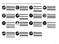
ASSEMBLY SYMBOL GUIDE•MONTAGE SYMBOLE•GUIDE DES SYMBOLES POUR ASSEMBLAGE•GUIDA AI SIMBOLI DI ASSEMBLAGGIO
15
OIL
L
R
L
R
x2
RT
CG
Use medium CA
Mittelfl üssigen
Sekundenkleber verwenden
Utilisez de la colle
cyanoacrylate moyenne
Usare colla ciano acrilica media
Use thin CA
Dünnfl üssigen
Sekundenkleber verwenden
Utilisez de la colle
cyanoacrylate fi ne
Usare colla ciano acrilica fi ne
Use a felt-tipped pen
Verwenden Sie einen Faserstift
Utilisez un feutre fi n effaçable
Usare un pennarello
Use 15-minute epoxy
Verwenden Sie 15 Minuten Epoxy
Utilisez de l’époxy 15 minutes
Usare una resina epossidica con
indurimento di 15 minuti
Ensure free rotation
Rotation sicherstellen
Permettez une rotation libre
Assicurarsi rotazione libera
Apply oil
Öl verwenden
Appliquez lubricant
Applicare olio
Attach temporarily
Vorübergehend anbringen
Attachez temporairement
Attaccare temporaneamente
Apply threadlock
Schraubensicherungslack verwenden
Utilisez du frein fi let
Applicare fuido threadlock
Assemble right and left
Links und rechts montieren
Assemblez à droite et à gauche
Assemblare destra e sinistra
Repeat multiple times
(as indicated)
Vorgang wiederholen
(wie angezeigt)
Répétez comme indiqué
Ripetere piu’ volte
(come indicato)
Ensure proper orientation
Ausrichtung/Richtung sicherstellen
Vérifi ez la bonne orientation
Assicurarsi dell’appropriato
orientamento
Rubber Toughened CA
Rubber Toughened CA
Colle CA caoutchouc
CA gommata
Canopy Glue
Kabinenhaubenkleber
Colle à verrière
Colla per capottine
Fully tighten
Vollständig festziehen/festschrauben
Serrez complètement
Stringere al massimo
Use hobby knife with
#11 blade
Verwenden Sie ein Hobbymesser mit #
11 Klinge
Utilisez un Couteau: Lame numéro 11
Usare taglierino per hobbistica con
lama numero 11

16
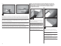
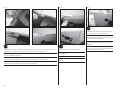
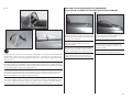
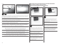
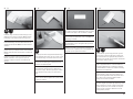
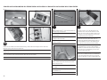
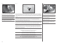
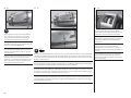
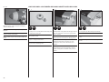
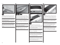
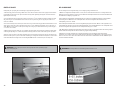
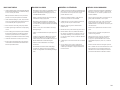
1
OIL
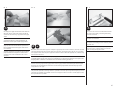
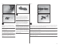
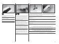
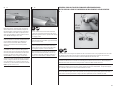
Fit the rear tab of the canopy frame into the track in the top of the fuselage. It may be required to lightly sand the tab on the
canopy to remove any excess paint, or the slot, to allow the canopy to slide smoothly. A drop of light machine oil placed onto
the carbon pin will also aid in allowing the canopy frame to slide easily in the track.
Passen Sie die hintere Führung des Kabinenhauberahmen in dem Führungschlitz im Rumpf ein. Es könnte dabei erforderlich
sein die Führung oder den Schlitz etwas nach zu schleifen um überschüssige Farbe zu entfernen. Ein Tropfen Nähmaschinenöl
auf den Carbonstift hilft auch, dass der Rahmen sauber in der Spur läuft.
Insérez la languette arrière du bâti dans la rainure supérieure du fuselage. Il sera peut être nécessaire de poncer légèrement
la peinture de la languette, ou de poncer l’intérieur de la rainure pour assurer le coulissement de la verrière. Une goutte
d’huile fi ne sur le téton en carbone facilitera également le mouvement de la verrière.
Inserire la linguetta posteriore del telaio della capottina nella scanalatura sulla parte superiore della fusoliera. Per facilitare
l’inserimento della capottina, potrebbe servire una leggera carteggiata della linguetta per togliere gli eccessi di vernice o un
allargamento della scanalatura. Una goccia di olio leggero messa sul perno in carbonio potrebbe facilitare l’inserimento.
2
Fit the forward tabs of the canopy frame into position. Again, lightly sand the tabs to remove any paint from the tabs, or
lightly sand the tracks so the canopy can slide smoothly in the tracks. The canopy moves downward as it slides back so if you
slightly angle the slot it will slide easier.
Passen Sie die vorderen Führungen des Kabinenhaubenrahmens ein. Schleifen Sie hier falls notwendig die Führungen nach
und Farbreste ab. Der Kabinenhaubenrahmen bewegt sich bei dem nach hinten schieben etwas nach unten. Wenn Sie die
Führung wie abgebildet etwas anwinkeln geht dieses leichter.
Placez en position les languettes avant du bâti de la verrière. Comme précédemment, poncez les languettes pour y retirer la
peinture, ou poncez l’intérieur des rainures pour obtenir le coulissement libre de la verrière. La verrière descend légèrement
quand elle retourne à sa position initiale, si en ponçant vous donnez un angle au languettes, la verrière coulissera plus
facilement.
Posizionare le linguette anteriori del telaio della capottina. Come prima carteggiare leggermente per togliere la vernice dalle
linguette o per adattare la scanalatura in modo che la capottina si possa inserire facilmente. La capottina si sposta verso il
basso scorrendo all’indietro, quindi una leggera angolazione delle scanalature favorisce questo scorrimento.
CANOPY FRAME INSTALLATION•MONTAGE DES KABINENHAUBENRAHMEN•INSTALLATION DU BÂTI DE LA VERRIÈRE•INSTALLAZIONE TELAIO CAPOTTINA

17
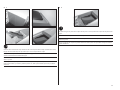
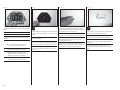
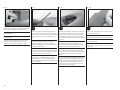
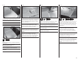
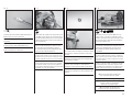
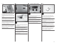
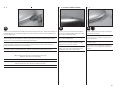
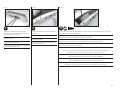
4
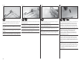
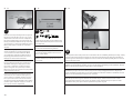
Remove the sliding frame from the fuselage. Sand the edge
of the plywood frame where it will make contact with the
canopy. Set the frame aside in a safe location.
Nehmen Sie den Rahmen vom Rumpf ab. Schleifen Sie die
Kanten an denen der Rahmen mit dem Rumpf in Berührung
kommt etwas an. Legen Sie ihn dann zur Seite.
Retirez du fuselage le bâti de la verrière. Poncez la face du
bâti en contreplaqué qui entrera en contact avec la verrière.
Rangez soigneusement le bâti.
Togliere il telaio dalla fusoliera. Carteggiare il bordo del
telaio in compensato nel punto in cui entra in contatto con la
capottina. Mettere da parte il telaio in posto sicuro.
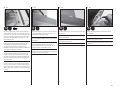
5
RT
Install the four 1mm plastic magnet spacers into the sliding canopy former. Sand all mating surfaces that will receive glue.
Setzen Sie die vier 1mm Kunststoffdistanzstücke in den Rahmen ein. Schleifen Sie alle Oberfl ächen an die mit Kleber in
Kontakt kommen.
Installez les 4 entretoises d’aimants en plastique de 1mm sur le couple coulissant de la verrière. Poncez toutes les surfaces
où les collages seront effectués.
Installare nel sistema di scorrimento della capottina, i 4 distanziali in plastica da 1mm per i magneti. Carteggiare tutte le
superfi ci di contatto che dovranno essere incollate.
3
Slide the canopy frame forward and back to check for any
places where the canopy frame is diffi cult to move. Glue a
piece of medium grit sandpaper to a thin piece of plywood or
a mixing stick. Lightly sand the tracks in the areas where the
canopy frame binds when opening and closing.
Schieben Sie den Rahmen vor und zurück um zu überprüfen
ob er ohne zu klemmen in der Führung läuft. Kleben Sie ein
Stück Schleifpapier auf ein Mischerstäbchen und führen es
an den Stellen lang wo der Rahmen klemmt.
Faites coulisser la structure en avant et en arrière pour
contrôler l’absence de points durs. Collez du papier abrasif
médium sur un fi n morceau de contreplaqué ou sur un bâton
mélangeur pour poncer les zones de la rainure où la verrière
coince durant l’ouverture ou la fermeture.
Far scorrere avanti e indietro il telaio della capottina per
vedere se ci sono dei punti in cui forza. Incollare su di un
pezzo sottile di compensato della carta vetro a grana media.
Carteggiare leggermente i punti dove la capottina forza.

18
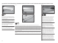
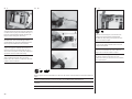
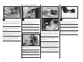
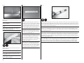
6
RT
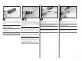
Install the magnets after sanding the one face of the magnet. Be sure to maintain the correct orientation of the magnets by
stacking the magnets and inserting them one at a time. Dry fi t the magnets to make sure they are properly aligned glue as
applied. Install four 1mm spacers into the front windscreen before installing the magnets into the front windscreen frame.
Setzen Sie die Magnete ein, nachdem Sie eine Seite angeschliffen haben. Bitte achten Sie darauf, dass die Magnete richtig
herum eingesetzt werden. Am besten geht das mit einem zweiten Magnet als Gegenstück und sollte vor dem Kleben geprüft
werden. Setzen Sie vier 1mm Distanzstücke in die vordere Windschutzscheibe bevor Sie die Magnete in den vorderen
Windschutzscheibenrahmen eingesetzt werden.
Installez les aimants après avoir poncé une de leurs faces. Assurez-vous de respecter l’orientation des aimants en les
empilant et en les collant 1 par 1. Effectuez un positionnement à blanc des aimant pour contrôler leur alignement avant de
les coller. Installez les entretoises de 1mm sur la partie fi xe du pare-brise avant d’y instaler les aimants.
Installare i magneti dopo aver carteggiato un loro lato. Accertarsi di mantenere l’orientamento corretto impilando i magneti
e inserendoli uno per volta. Inserire a secco i magneti per essere sicuri che siano allineati correttamente prima di incollarli.
Installare i 4 distanziali da 1mm nel parabrezza anteriore prima di installare i magneti nel telaio corrispondente.
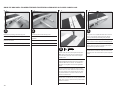
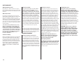
2
RT
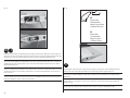
Test fi t the rear panel into the cockpit. Trim the panel as
necessary to fi t into the cockpit. Glue the rear panel into the
cockpit.
Prüfen Sie die Passung des hinteren Panels und passen es
ggfl s. an. Kleben Sie das Panel ein.
Positionnez le panneau arrière à l’intérieur du cockpit.
Effectuez les ajustements nécessaires à son installation.
Collez le panneau arrière en position.
Provare a posizionare il pannello posteriore nell’abitacolo
rifi landolo adeguatamente. Quando è a posto, incollarlo.
1
RT
Fit the rear lower cockpit panel into position, Trim the edges
at the top so it is fl ush with the edge of the cockpit. Glue the
rear cockpit panel into the cockpit.
Passen Sie das unteren hintere Cockpitpanel ein. Passen Sie
die Kanten bündig zur Kante an und kleben es ein.
Placez le panneau inférieur arrière en position, ajustez les
arrête de façon que son arrête supérieure tangente l’arrête
supérieure du cockpit. Collez-le en position.
Posizionare il pannello posteriore inferiore dell’abitacolo,
rifi lare i bordi superiori in modo che sia a fi lo dell’abitacolo.
Incollare nell’abitacolo il pannello posteriore.
COCKPIT SIDE AND REAR PANEL INSTALLATION•EINBAU DER SEITLICHEN UND
HINTEREN COCKPITSCHIENEN•INSTALLATION DES PANNEAUX LATÉRAUX ET DU
PANNEAU ARRIÈRE DU COCKPIT•INSTALLAZIONE DEL PANNELLO LATERALE E
POSTERIORE DELL’ABITACOLO

19
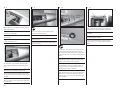
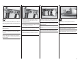
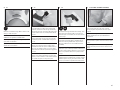
3
RT
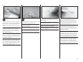
Test fi t the lower rear wall into the cockpit. Trim the rear wall as necessary to fi t into the cockpit. Install the lower rear wall,
then glue the rear fl oor with the plastic stops. Trim the pieces as necessary to fi t into the cockpit.
Prüfen Sie die Passung der hinteren Rückwand und passen diese ggfl s. an. Kleben Sie die untere hintere Wand in das Cockpit
und danach den Fußboden mit den Kunststoffstoppern.
Positionnez le fond de la partie arrière à l’intérieur du cockpit. Effectuez les ajustements nécessaires à son installation,
collez-le en position.
Provare a posizionare la parete posteriore nell’abitacolo. Rifi larla quanto serve per adattarla perfettamente. Installare la
parete posteriore inferiore, poi incollare il pavimento posteriore con i fermi in plastica. Rifi lare quanto serve per adattarli
all’abitacolo.
4
RT
Test fi t the rear upper side panels into the cockpit. Trim the panels as necessary to fi t into the cockpit. Glue the panels into the
cockpit.
Setzen Sie die oberen Seitenpanele testweise in das Cockpit ein. Passen Sie die Panele an und kleben diese ein.
Positionnez les panneaux latéraux supérieurs. Effectuez les ajustements nécessaire à leur positionnement. Collez les
panneaux en position.
Provare a posizionare il lato superiore dei pannelli nell’abitacolo e rifi lare quanto serve per adattarlo al meglio. Poi incollare i
pannelli nell’abitacolo.

20
5
RT
Test fi t the cockpit side panels into the cockpit. Trim the side panels as necessary to fi t into the cockpit. Insert the small
angled fi ller pieces to the rear edge of the cockpit side panels and trim as needed and glue into place.
Setzen Sie Seitenpanele testweise in das Cockpit ein. Passen Sie die Panele an und setzen die angewinkelten Füllstücke mit in
das Cockpit ein und kleben Sie diese fest.
Positionnez les panneaux latéraux à l’intérieur du cockpit. Effectuez les ajustements nécessaires à leur installation. Les deux
lignes de décorations se rejoignent vers l’avant du fuselage. Plaquez les panneaux contre l’arrête arrière.
Provare a posizionare i pannelli laterali nell’abitacolo rifi landoli quanto serve per adattarli al meglio. Inserire nel bordo
posteriore dell’abitacolo i riempitivi piccoli angolati, rifi lare e incollare il tutto.
6
RT
Glue the side panels in place using rubberized CA.
Kleben Sie die Seitenpanele mit dickfl üssigen
Sekundenkleber ein.
Collez les panneaux en utilisant la colle CA caoutchouc.
Incollare al loro posto i pannelli laterali usando CA
gommata.
7
RT
Fit and trim the front top fi ller pieces and then glue in place
using rubberized CA. Sand all mating surfaces fi rst.
Passen Sie die oberen Füllstücke an und kleben diese auch
mit dickfl üssigen Sekundenkleber ein. Bitte denken Sie daran
alle Klebefl ächen vorher anzuschleifen.
Positionnez et ajustez les plaques supérieures avant, poncez
toutes les surfaces de contact et collez-les à l’aide de colle
CA caoutchouc.
Posizionare e rifi lare i pezzi del riempitivo anteriore superiore
e poi incollarli al loro posto usando colla CA gommata. Prima
carteggiare tutte le superfi ci di contatto.

21
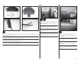
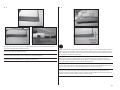
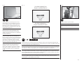
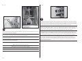
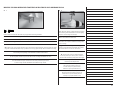
1
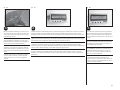
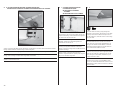
Install the instrument decal onto the balsa former, aligning
the bottom edge of the decal with the former.
Setzen Sie das Kunststoffi nstrumentenpanel auf das
Balsabrett und richten die Unterkanten passend aus.
Installez sur le couple en balsa l’autocollant représentant
les instruments, alignez l’arrête du bas de l’autocollant sur
l’arrête du bas du couple en balsa.
Piazzare l’adesivo degli strumenti sulla base in balsa,
allineandosi al bordo inferiore.
2
Cut back the outer edges of the decal exposing the area
where the wood will be glued to the back of the plastic
instrument housing.
Schneiden Sie die äußeren Kanten des Kunststoffteils an den
Stellen wo das Teil mit dem Holzpanel verklebt wird etwas
zurück.
Découpez le tour extérieur de l’autocollant où le bois sera
collé contre le dos de l’entourage des instruments en
plastique.
Tagliare i bordi esterni dell’adesivo per esporre il legno che
sarà incollato sul retro della sede in plastica degli strumenti.
3
Use a hobby knife to cut through the paint and lightly score
the underlying plastic in the instrument panel. Prepare all
the openings for the gauges at this time.
Schneiden Sie mit einem Hobbymesser durch die Farbe
und ritzen vorsichtig das darunterliegende Plastik des
Instrumentenpanels an. Bereiten Sie so alle Öffnungen im
Instrumentenbrett vor.
Utilisez un couteau de modélisme pour couper le fi lm de
peinture en marquant légèrement le plastique de l’entourage
des instruments. Préparez tous les entourages d’instruments
durant cette étape.
Con un coltello tagliabalsa tagliare attraverso la vernice e
segnare leggermente la plastica sottostante sul cruscotto. A
questo punto preparare tutte le aperture per gli strumenti.
4
Lightly sand the back of the instrument panel. This will
thin the plastic, allowing the openings for the gauges to be
removed so the decal can be seen when installed in the rear
of the instrument panel.
Schleifen Sie etwas die Rückseite des Instrumentenpanels
an. So können die Instrumentenöffnungen der verjüngten
Rückseite entfernt werden. Sie sehen dann von hinten auf
die Instrumente.
Poncez légèrement l’arrière du panneau d’instruments.
Cela va affi ner le plastique, et le fond des instruments
pourra être retiré pour laisser apparaître les instruments de
l’autocollant.
Carteggiare leggermente il retro del pannello strumenti.
Questo assottiglierà la plastica, permettendo di togliere
agevolmente le aperture per gli strumenti, permettendo di
vedere meglio l’adesivo quando verrà installato sul retro del
cruscotto.
INSTRUMENT PANEL AND HOOD INSTALLATION•EINBAU DES INSTRUMENTENPANELS•INSTALLATION DU TABLEAU DE BORD•INSTALLAZIONE PANNELLO STRUMENTI E COFANO
Page is loading ...

23
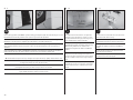
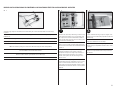
9
RT
Use sandpaper to remove the paint from the upper instrument panel where the balsa will be glued. Use rubberized CA to glue
the lower instrument panel into position.
Entfernen Sie mit Schleifpapier die Farbe von dem oberem Instrumentenpanel an denen das Balsaholz verklebt wird. Kleben
Sie mit dickfl üssigen Sekundenkleber das untere Instrumentenpanel in Position.
Utilisez du papier à poncer pour retirer la peinture du panneau supérieur aux emplacements où le balsa sera collé. Utilisez la
colle CA caoutchouc pour coller le panneau inférieur en position.
Con la carta vetrata togliere la vernice dalla parte superiore del pannello strumenti dove verrà incollato il balsa. Incollare la
parte inferiore del pannello strumenti con colla CA gommata.
10
RT
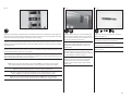
Trim the width of the instrument panel as needed to allow
the panel to fi t into the cockpit 3mm forward from the raised
edge of the cockpit sides.
Schneiden Sie die Breite des Instrumentenpanels wie
benötigt, damit es 3mm vor der nach oben laufenden
Seitenkante in das Cockpit passt.
Ajustez la largeur du tableau de bord afi n de pouvoir
l’installer 3 mm en avant de la sur-épaisseur des panneaux
latéraux.
Ritoccare in larghezza il pannello strumenti per farlo entrare
nell’abitacolo a 3mm davanti ai bordi rialzati sui fi anchi
dell’abitacolo.
11
RT
Remove a section of paint where the instrument panel
will glue into the cockpit. Use rubberized CA to install the
instrument panel.
Entfernen Sie an der Klebestelle die Farbe. Verwenden
Sie zum Kleben des Instrumentenpanels dickfl üssigen
Sekundenkleber.
Retirez la peinture où le tableau de bord sera collé au
cockpit. Utilisez de la colle CA caoutchouc pour fi xer le
tableau de bord.
Togliere una parte di vernice dove il pannello strumenti si
incollerà al cruscotto. Per fi ssare il pannello strumenti usare
colla CA gommata.

24
12
CG
Carefully fi t and trim the instrument panel hood so it rests in the recess on the sides of the fuselage. The hood will key to the
instrument panel during the fi tting, and the instrument panel will set back roughly 5/52 inch (4mm) inside the instrument
panel hood. The instrument panel hood must be fl ush or below the top edge of the fuselage to allow the canopy to mount.
Sand all the edges of the black hood that will be glued and be cautious to not sand any areas that will be visible from inside
the front lip of the cockpit.
Passen Sie vorsichtig die Instrumentenabdeckung an, so dass diese in die Ausbuchtung an den Rumpfseiten passt. Das
Panel sitzt dabei ca 4mm in der Abdeckung versenkt. Die Abdeckung muß bündig mit dem Rumpf abschließen damit die
Kabinenhaube passt. Schleifen Sie alle Klebestellen an und achten darauf keine Stellen anzuschleifen die später im Cockpit
zu sehen sind.
Ajustez délicatement la casquette de tableau de bord aux fl ancs du fuselage. Le tableau de bord doit être à 4mm à l’intérieur
de la casquette. L’avant de la casquette doit parfaitement tangenter le dessus du fuselage ou se trouver légèrement dessous.
Poncez les arrêtes du tableau de bord qui seront collées, ne pas poncer les parties qui resteront visibles après l’installation de
la casquette.
Adattare accuratamente la parte superiore del pannello strumenti in modo che resti nella cavità sui fi anchi della fusoliera.
La parte superiore deve agganciarsi al pannello strumenti durante l’aggiustamento, e il pannello strumenti sarà arretrato di
circa 4mm all’interno della parte superiore che deve essere a fi lo o appena sotto al bordo superiore della fusoliera, per poter
montare la capottina. Carteggiare tutti i bordi della parte superiore nera che poi verranno incollati facendo attenzione a non
carteggiare le aree che saranno visibili dall’interno del bordo anteriore della capottina.
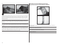
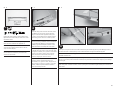
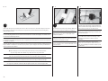
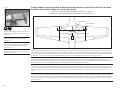
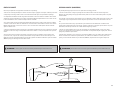
1
Fit the two canopy formers together, fi tting the small carbon pin in the holes at the top of the formers. Check that the pin
slides into both holes.
Montieren Sie die beiden Kabinenhauben zusammen und setzen den kleinen Carbonstift in die Öffnung an der Oberseite.
Prüfen Sie bitte, dass der Stift durch beide Löcher geht.
Placez les deux couples de la verrière l’un contre l’autre, insérez les plots en carbone dans les trous situés en haut des
couples. Contrôlez que le plot est bien inséré dans les deux couples.
Accoppiare le due ordinate della capottina, inserendo i piccoli perni in carbonio nei fori sopra alle ordinate. Accertarsi che i
perni vadano in entrambi i fori.
WINDSCREEN INSTALLATION•MONTAGE DER FRONTSCHEIBE•
INSTALLATION DU PARE-BRISE•INSTALLAZIONE DEL PARABREZZA

25
2
RT
Remove the pin and sand the last 3mm end of the pin where it will be glued into the sliding canopy framing. Remove any
paint from inside the canopy frame pin hole. Use rubberized CA to glue the pin in place to only the sliding canopy frame. Make
sure the pin is aligned squarely to the formers. Round the end of the pin to aid in alignment when operating the canopy.
Nehmen Sie den Stift heraus und schleifen die letzten 3mm des Stiftes dort wo er geklebt wird an. Entfernen Sie in der
Öffnung alle Farbe und kleben den Stift ein. Bitte überprüfen Sie, dass der Stift im Rahmen korrekt ausgerichtet ist.
Verrunden Sie die Enden des Stiftes.
Retirez le plot et poncez ses 3 derniers millimètres où il sera collé à la structure coulissante de la verrière. Retirez la peinture
présente à l’intérieur du trou destiné à recevoir le plot. Utilisez la colle CA caoutchouc pour coller le plot à la structure
coulissante. Assurez-vous que le plot est parfaitement à la perpendiculaire des couples. Arrondissez l’extrémité du plot pour
faciliter l’alignement quand la verrière est manœuvrée.
Togliere i perni e carteggiarne gli ultimi 3mm che verranno incollati nel telaio scorrevole della capottina. Togliere le tracce di
vernice dall’interno dei fori per i perni che verranno incollati solo alla parte scorrevole del telaio della capottina con colla CA
gommata. Accertarsi che il perno sia allineato ad angolo retto alle ordinate. Arrotondare i terminali dei perni per facilitare
l’allineamento.
3
15
Remove the shipping doublers from the bottom of the windscreen former. Insert the canopy sliding frame into the fuselage
and move to the closed position. Place the windscreen former in place and glue the bottoms to the fuselage using epoxy.
Entfernen Sie die Transportsicherung aus der Unterseite des Frontscheibenrahmens. Setzen Sie den Rahmen in den Rumpf
und schieben ihn in die Position “Haube geschlossen”. Setzen Sie den Frontscheibenrahmen und kleben das Unterteil mit
Epoxy an den Rumpf.
Retirez le renfort temporaire du bas du couple du pare-brise. Insérez la structure coulissante sur le fuselage et placez-la en
position fermée. Positionnez le couple du pare-brise et collez sa partie basse au fuselage en utilisant de la colle époxy.
Togliere lo “shipping doubler” dalla parte inferiore dell’ordinata del parabrezza. Inserire il telaio scorrevole della capottina
nella fusoliera e spostarlo nella posizione di chiuso. Mettere al suo posto l’ordinata del parabrezza e incollare il fondo alla
fusoliera con colla epoxy.
Page is loading ...
Page is loading ...
Page is loading ...
Page is loading ...
Page is loading ...
Page is loading ...
Page is loading ...
Page is loading ...
Page is loading ...
Page is loading ...
Page is loading ...
Page is loading ...
Page is loading ...
Page is loading ...
Page is loading ...
Page is loading ...
Page is loading ...
Page is loading ...
Page is loading ...
Page is loading ...
Page is loading ...
Page is loading ...
Page is loading ...
Page is loading ...
Page is loading ...
Page is loading ...
Page is loading ...
Page is loading ...
Page is loading ...
Page is loading ...
Page is loading ...
Page is loading ...
Page is loading ...
Page is loading ...
Page is loading ...
Page is loading ...
Page is loading ...
Page is loading ...
Page is loading ...
Page is loading ...
Page is loading ...
Page is loading ...
Page is loading ...
Page is loading ...
Page is loading ...
Page is loading ...
Page is loading ...
Page is loading ...
Page is loading ...
Page is loading ...
Page is loading ...
Page is loading ...
Page is loading ...
Page is loading ...
Page is loading ...
Page is loading ...
Page is loading ...
Page is loading ...
Page is loading ...
Page is loading ...
Page is loading ...
Page is loading ...
Page is loading ...
Page is loading ...
Page is loading ...
Page is loading ...
Page is loading ...
Page is loading ...
Page is loading ...
Page is loading ...
Page is loading ...
Page is loading ...
Page is loading ...
Page is loading ...
Page is loading ...
Page is loading ...
Page is loading ...
Page is loading ...
Page is loading ...
Page is loading ...
Page is loading ...
Page is loading ...
Page is loading ...
Page is loading ...
Page is loading ...
Page is loading ...
Page is loading ...
-
 1
1
-
 2
2
-
 3
3
-
 4
4
-
 5
5
-
 6
6
-
 7
7
-
 8
8
-
 9
9
-
 10
10
-
 11
11
-
 12
12
-
 13
13
-
 14
14
-
 15
15
-
 16
16
-
 17
17
-
 18
18
-
 19
19
-
 20
20
-
 21
21
-
 22
22
-
 23
23
-
 24
24
-
 25
25
-
 26
26
-
 27
27
-
 28
28
-
 29
29
-
 30
30
-
 31
31
-
 32
32
-
 33
33
-
 34
34
-
 35
35
-
 36
36
-
 37
37
-
 38
38
-
 39
39
-
 40
40
-
 41
41
-
 42
42
-
 43
43
-
 44
44
-
 45
45
-
 46
46
-
 47
47
-
 48
48
-
 49
49
-
 50
50
-
 51
51
-
 52
52
-
 53
53
-
 54
54
-
 55
55
-
 56
56
-
 57
57
-
 58
58
-
 59
59
-
 60
60
-
 61
61
-
 62
62
-
 63
63
-
 64
64
-
 65
65
-
 66
66
-
 67
67
-
 68
68
-
 69
69
-
 70
70
-
 71
71
-
 72
72
-
 73
73
-
 74
74
-
 75
75
-
 76
76
-
 77
77
-
 78
78
-
 79
79
-
 80
80
-
 81
81
-
 82
82
-
 83
83
-
 84
84
-
 85
85
-
 86
86
-
 87
87
-
 88
88
-
 89
89
-
 90
90
-
 91
91
-
 92
92
-
 93
93
-
 94
94
-
 95
95
-
 96
96
-
 97
97
-
 98
98
-
 99
99
-
 100
100
-
 101
101
-
 102
102
-
 103
103
-
 104
104
-
 105
105
-
 106
106
-
 107
107
-
 108
108
-
 109
109
-
 110
110
-
 111
111
-
 112
112


Hangar 9 HAN4770 Owner's manual
- Category
- Remote controlled toys
- Type
- Owner's manual
Ask a question and I''ll find the answer in the document
Finding information in a document is now easier with AI
in other languages
- italiano: Hangar 9 HAN4770 Manuale del proprietario
- français: Hangar 9 HAN4770 Le manuel du propriétaire
- Deutsch: Hangar 9 HAN4770 Bedienungsanleitung
Related papers
-
 Hangar 9 HAN5280 Owner's manual
-
Horizon Hobby Hangar 9 Ki-43 Oscar 60cc Owner's manual
-
 Hangar 9 HAN4670 Owner's manual
-
 Hangar 9 HAN2530 Owner's manual
-
Evolution HAN5060 Owner's manual
-
 Hangar 9 HAN6030 Owner's manual
-
 Hangar 9 HAN3390 User manual
-
 Hangar 9 HAN5065 Owner's manual
-
 Hangar 9 HAN5260B Owner's manual
-


Other documents
-
Kimex 032-1014 Installation guide
-
 BLOTZ B28-SF-232 Assembly Instructions
-
E-flite Habu 32 EDF ARF User manual
-
-
-
Ripmax Phase 5 E User manual
-
arf PA-20 Pacer 10e Owner's manual
-
E-flite Beast 60e User manual
-
Blade SR UH-1 User manual
-
Evolution EVOE10GX User manual
