Page is loading ...

68-1994-01 Rev. A
06 12
High Resolution Fiber Optic Transmitters and Receivers
PowerCage FOX Tx/Rx HDMI
User Guide
Fiber Optic Extenders

This symbol is intended to alert the user of important operating and mainte-
nance (servicing) instructions in the literature provided with the equipment.
This symbol is intended to alert the user of the presence of uninsulated
dangerous voltage within the product’s enclosure that may present a risk of
electric shock.
Caution
Read Instructions • Read and understand all safety and operating instructions before using the equipment.
Retain Instructions • The safety instructions should be kept for future reference.
Follow Warnings • Follow all warnings and instructions marked on the equipment or in the user information.
Avoid Attachments • Do not use tools or attachments that are not recommended by the equipment
manufacturer because they may be hazardous.
Warning
Power sources • This equipment should be operated only from the power source indicated on the product. This
equipment is intended to be used with a main power system with a grounded (neutral) conductor. The third
(grounding) pin is a safety feature, do not attempt to bypass or disable it.
Power disconnection • To remove power from the equipment safely, remove all power cords from the rear of
the equipment, or the desktop power module (if detachable), or from the power source receptacle (wall plug).
Power cord protection • Power cords should be routed so that they are not likely to be stepped on or pinched
by items placed upon or against them.
Servicing • Refer all servicing to qualified service personnel. There are no user-serviceable parts inside. To prevent
the risk of shock, do not attempt to service this equipment yourself because opening or removing covers may
expose you to dangerous voltage or other hazards.
Slots and openings • If the equipment has slots or holes in the enclosure, these are provided to prevent
overheating of sensitive components inside. These openings must never be blocked by other objects.
Lithium battery • There is a danger of explosion if battery is incorrectly replaced. Replace it only with the
same or equivalent type recommended by the manufacturer. Dispose of used batteries according to the
manufacturer’s instructions.
Ce symbole sert à avertir l’utilisateur que la documentation fournie avec le
matériel contient des instructions importantes concernant l’exploitation et la
maintenance (réparation).
Ce symbole sert à avertir l’utilisateur de la présence dans le boîtier
de l’appareil de tensions dangereuses non isolées posant des risques
d’électrocution.
Attention
Lire les instructions• Prendre connaissance de toutes les consignes de sécurité et d’exploitation avant
d’utiliser le matériel.
Conserver les instructions• Ranger les consignes de sécurité afin de pouvoir les consulter à l’avenir.
Respecter les avertissements • Observer tous les avertissements et consignes marqués sur le matériel ou
présentés dans la documentation utilisateur.
Eviter les pièces de xation • Ne pas utiliser de pièces de fixation ni d’outils non recommandés par le
fabricant du matériel car cela risquerait de poser certains dangers.
Avertissement
Alimentations • Ne faire fonctionner ce matériel qu’avec la source d’alimentation indiquée sur l’appareil. Ce
matériel doit être utilisé avec une alimentation principale comportant un fil de terre (neutre). Le troisième
contact (de mise à la terre) constitue un dispositif de sécurité : n’essayez pas de la contourner ni de la
désactiver.
Déconnexion de l’alimentation• Pour mettre le matériel hors tension sans danger, déconnectez tous les
cordons d’alimentation de l’arrière de l’appareil ou du module d’alimentation de bureau (s’il est amovible) ou
encore de la prise secteur.
Protection du cordon d’alimentation • Acheminer les cordons d’alimentation de manière à ce que personne
ne risque de marcher dessus et à ce qu’ils ne soient pas écrasés ou pincés par des objets.
Réparation-maintenance • Faire exécuter toutes les interventions de réparation-maintenance par un
technicien qualifié. Aucun des éléments internes ne peut être réparé par l’utilisateur. Afin d’éviter tout danger
d’électrocution, l’utilisateur ne doit pas essayer de procéder lui-même à ces opérations car l’ouverture ou le
retrait des couvercles risquent de l’exposer à de hautes tensions et autres dangers.
Fentes et orices • Si le boîtier de l’appareil comporte des fentes ou des orifices, ceux-ci servent à empêcher les
composants internes sensibles de surchauffer. Ces ouvertures ne doivent jamais être bloquées par des objets.
Lithium Batterie • Il a danger d’explosion s’ll y a remplacment incorrect de la batterie. Remplacer uniquement
avec une batterie du meme type ou d’un ype equivalent recommande par le constructeur. Mettre au reut les
batteries usagees conformement aux instructions du fabricant.
Safety Instructions • English
Consignes de Sécurité • Français
Sicherheitsanleitungen • Deutsch
Dieses Symbol soll dem Benutzer in der im Lieferumfang enthaltenen
Dokumentation besonders wichtige Hinweise zur Bedienung und Wartung
(Instandhaltung) geben.
Dieses Symbol soll den Benutzer darauf aufmerksam machen, daß im Inneren
des Gehäuses dieses Produktes gefährliche Spannungen, die nicht isoliert sind
und die einen elektrischen Schock verursachen können, herrschen.
Achtung
Lesen der Anleitungen • Bevor Sie das Gerät zum ersten Mal verwenden, sollten Sie alle Sicherheits-und
Bedienungsanleitungen genau durchlesen und verstehen.
Aufbewahren der Anleitungen • Die Hinweise zur elektrischen Sicherheit des Produktes sollten Sie
aufbewahren, damit Sie im Bedarfsfall darauf zurückgreifen können.
Befolgen der Warnhinweise • Befolgen Sie alle Warnhinweise und Anleitungen auf dem Gerät oder in der
Benutzerdokumentation.
Keine Zusatzgeräte • Verwenden Sie keine Werkzeuge oder Zusatzgeräte, die nicht ausdrücklich vom
Hersteller empfohlen wurden, da diese eine Gefahrenquelle darstellen können.
Vorsicht
Stromquellen • Dieses Gerät sollte nur über die auf dem Produkt angegebene Stromquelle betrieben werden.
Dieses Gerät wurde für eine Verwendung mit einer Hauptstromleitung mit einem geerdeten (neutralen) Leiter
konzipiert. Der dritte Kontakt ist für einen Erdanschluß, und stellt eine Sicherheitsfunktion dar. Diese sollte nicht
umgangen oder außer Betrieb gesetzt werden.
Stromunterbrechung • Um das Gerät auf sichere Weise vom Netz zu trennen, sollten Sie alle Netzkabel aus der
Rückseite des Gerätes, aus der externen Stomversorgung (falls dies möglich ist) oder aus der Wandsteckdose
ziehen.
Schutz des Netzkabels • Netzkabel sollten stets so verlegt werden, daß sie nicht im Weg liegen und niemand
darauf treten kann oder Objekte darauf- oder unmittelbar dagegengestellt werden können.
Wartung • Alle Wartungsmaßnahmen sollten nur von qualiziertem Servicepersonal durchgeführt werden.
Die internen Komponenten des Gerätes sind wartungsfrei. Zur Vermeidung eines elektrischen Schocks
versuchen Sie in keinem Fall, dieses Gerät selbst öffnen, da beim Entfernen der Abdeckungen die Gefahr eines
elektrischen Schlags und/oder andere Gefahren bestehen.
Schlitze und Öffnungen • Wenn das Gerät Schlitze oder Löcher im Gehäuse aufweist, dienen diese zur
Vermeidung einer Überhitzung der empndlichen Teile im Inneren. Diese Öffnungen dürfen niemals von
anderen Objekten blockiert werden.
Litium-Batterie • Explosionsgefahr, falls die Batterie nicht richtig ersetzt wird. Ersetzen Sie verbrauchte Batterien
nur durch den gleichen oder einen vergleichbaren Batterietyp, der auch vom Hersteller empfohlen wird.
Entsorgen Sie verbrauchte Batterien bitte gemäß den Herstelleranweisungen.
Este símbolo se utiliza para advertir al usuario sobre instrucciones impor-
tantes de operación y mantenimiento (o cambio de partes) que se desean
destacar en el contenido de la documentación suministrada con los equipos.
Este símbolo se utiliza para advertir al usuario sobre la presencia de elemen-
tos con voltaje peligroso sin protección aislante, que puedan encontrarse
dentro de la caja o alojamiento del producto, y que puedan representar
riesgo de electrocución.
Precaucion
Leer las instrucciones • Leer y analizar todas las instrucciones de operación y seguridad, antes de usar el
equipo.
Conservar las instrucciones • Conservar las instrucciones de seguridad para futura consulta.
Obedecer las advertencias • Todas las advertencias e instrucciones marcadas en el equipo o en la
documentación del usuario, deben ser obedecidas.
Evitar el uso de accesorios • No usar herramientas o accesorios que no sean especificamente recomendados
por el fabricante, ya que podrian implicar riesgos.
Advertencia
Alimentación eléctrica • Este equipo debe conectarse únicamente a la fuente/tipo de alimentación eléctrica
indicada en el mismo. La alimentación eléctrica de este equipo debe provenir de un sistema de distribución
general con conductor neutro a tierra. La tercera pata (puesta a tierra) es una medida de seguridad, no
puentearia ni eliminaria.
Desconexión de alimentación eléctrica • Para desconectar con seguridad la acometida de alimentación
eléctrica al equipo, desenchufar todos los cables de alimentación en el panel trasero del equipo, o desenchufar
el módulo de alimentación (si fuera independiente), o desenchufar el cable del receptáculo de la pared.
Protección del cables de alimentación • Los cables de alimentación eléctrica se deben instalar en lugares
donde no sean pisados ni apretados por objetos que se puedan apoyar sobre ellos.
Reparaciones/mantenimiento • Solicitar siempre los servicios técnicos de personal calicado. En el interior no
hay partes a las que el usuario deba acceder. Para evitar riesgo de electrocución, no intentar personalmente la
reparación/mantenimiento de este equipo, ya que al abrir o extraer las tapas puede quedar expuesto a voltajes
peligrosos u otros riesgos.
Ranuras y aberturas • Si el equipo posee ranuras o orificios en su caja/alojamiento, es para evitar el
sobrecalientamiento de componentes internos sensibles. Estas aberturas nunca se deben obstruir con otros
objetos.
Batería de litio • Existe riesgo de explosión si esta batería se coloca en la posición incorrecta. Cambiar esta
batería únicamente con el mismo tipo (o su equivalente) recomendado por el fabricante. Desachar las baterías
usadas siguiendo las instrucciones del fabricante.
Instrucciones de seguridad • Español
安全须知 • 中文
这个符号提示用户该设备用户手册中有重要的操作和维护说明。
这个符号警告用户该设备机壳内有暴露的危险电压,有触电危险。
注意
阅读说明书 • 用户使用该设备前必须阅读并理解所有安全和使用说明。
保存说明书 • 用户应保存安全说明书以备将来使用。
遵守警告 • 用户应遵守产品和用户指南上的所有安全和操作说明。
避免追加 • 不要使用该产品厂商没有推荐的工具或追加设备,以避免危险。
警告
电源 • 该设备只能使用产品上标明的电源。 设备必须使用有地线的供电系统供电。 第三条线
(地线)是安全设施,不能不用或跳过 。
拔掉电源 • 为安全地从设备拔掉电源,请拔掉所有设备后或桌面电源的电源线,或任何接到市
电系统的电源线。
电源线保护 • 妥善布线, 避免被踩踏,或重物挤压。
维护 • 所有维修必须由认证的维修人员进行。 设备内部没有用户可以更换的零件。为避免出现
触电危险不要自己试图打开设备盖子维修该设备。
通风孔 • 有些设备机壳上有通风槽或孔,它们是用来防止机内敏感元件过热。 不要用任何东
西挡住通风孔。
锂电池 • 不正确的更换电池会有爆炸的危险。必须使用与厂家推荐的相同或相近型号的电池。
按照生产厂的建议处理废弃电池。

FCC Class A Notice
This equipment has been tested and found to comply with the limits for a Class A digital device, pursuant to part 15
of the FCC Rules. Operation is subject to the following two conditions:
This device may not cause harmful interference.
1. This device must accept any interference received, including interference that may cause undesired operation.
The Class A limits are designed to provide reasonable protection against harmful interference when the equipment
is operated in a commercial environment. This equipment generates, uses, and can radiate radio frequency energy
and, if not installed and used in accordance with the instruction manual, may cause harmful interference to radio
communications. Operation of this equipment in a residential area is likely to cause harmful interference, in which
case the user will be required to correct the interference at his own expense.
NOTE: This unit was tested with shielded cables on the peripheral devices. Shielded cables must be used with
the unit to ensure compliance with FCC emissions limits.
For more information on safety guidelines, regulatory compliances, EMI/EMF compliance, accessibility, and
related topics, click here.

Conventions Used in this Guide
Notifications the following are used:
DANGER: A danger indicates a situation that will result in death or severe injury.
WARNING: A warning indicates a situation that has the potential to result in death or
severe injury.
CAUTION: A caution indicates a situation that may result in minor injury.
ATTENTION: Attention indicates a situation that may damage or destroy the product or
associated equipment.
NOTE: A note draws attention to important information.
TIP: A tip provides a suggestion to make working with the application easier.
Software Commands
Commands are written in the fonts shown here:
^AR Merge Scene,,Op1 scene 1,1 ^B 51 ^W^C
[01] R 0004 00300 00400 00800 00600 [02] 35 [17] [03]
E X! *X1&* X2)* X2#* X2! CE}
NOTE: For commands and examples of computer or device responses mentioned
in this guide, the character “0” is used for the number zero and “O”
represents the capital letter “o.”
Computer responses and directory paths that do not have variables are written in the font
shown here:
Reply from 208.132.180.48: bytes=32 times=2ms TTL=32
C:\Program Files\Extron
Variables are written in slanted form as shown here:
ping xxx.xxx.xxx.xxx —t
SOH R Data STX Command ETB ETX
Selectable items, such as menu names, menu options, buttons, tabs, and field names are
written in the font shown here:
From the File menu, select New.
Click the OK button.
Copyright
© 2012 Extron Electronics. All rights reserved.
Trademarks
All trademarks mentioned in this guide are the properties of their respective owners.

Contents
Introduction ............................................ 1
About this Guide ............................................. 1
About the PowerCage FOX HDMI
Transmitters and Receivers .............................. 2
Transmitter ................................................... 2
Receiver ....................................................... 2
Transmitter and Receiver .............................. 3
System Compatibility ................................... 3
Cable Transmission Modes ........................... 3
Features ........................................................... 4
Installation and Operation ..................... 5
Mounting the Units.......................................... 5
Rear Panel Connections, Controls, and
Indications ...................................................... 5
Making Connections .................................. 10
Transmitter Side Panel Controls ...................... 13
PowerCage Front Panel Port, Control, and
Indicators ...................................................... 14
Operation ...................................................... 16
Remote Control ......................................17
Serial Ports ..................................................... 17
Simple Instruction Set Control ........................ 18
Host-to-unit Instructions ............................ 18
Unit-initiated Messages .............................. 18
Error Responses.......................................... 18
Using the Command and Response
Tables ....................................................... 19
FOX Extenders Control Program ..................... 26
Installing the Software ............................... 26
Starting the Program .................................. 26
Firmware Upgrade ..................................... 33
Reference Information ..........................37
Specifications ................................................. 37
Part Numbers ................................................. 40
PowerCage FOX Part Numbers ................... 40
Included Parts ............................................ 40
Cables ....................................................... 40
Adapters .................................................... 41
Installing a Board in the Enclosure .................. 42
PowerCage FOX HDMI • Contents v


Introduction
WARNING: The PowerCage™ Tx/Rx HDMI units output continuous invisible light,
which may be harmful to the eyes; use with caution.
• Do not look into the rear panel fiber optic cable connectors or into the
fiber optic cables themselves.
• Plug the attached dust caps into the optical transceivers when the fiber
cable is unplugged.
• About this Guide
• About the PowerCage FOX HDMI Transmitters and Receivers
• Features
About this Guide
This guide contains information about the Extron® PowerCage FOX Tx HDMI transmitter
and PowerCage FOX Rx HDMI receiver. These units are modular board-designed ber optic
transmitters and receivers for the PowerCage Modular Power Enclosures.
PowerCage 1600
Power Supply
N15778
C US
LISTED
1T23
L.T.E.
5A MAX.
100-240V 50/60Hz
1 2
REMOTE
RS-232
RS-232
OVER FIBER
Tx Rx
Tx
ALARM
Rx
OUTPUTS
PowerCage
FOX Rx HDMI
Tx Rx
LR
AUDIO
HDMI
HDCP
ON
HDMI
AUDIO
OFF
AUDIO
1 2
REMOTE
RS-232
RS-232
OVER FIBER
Tx Rx
Tx
ALARM
INPUTS
PowerCage
FOX Tx HDMI
Tx Rx
AUDIO
HDMI
HDCP
HDMI
AUDIO
Rx
12V
1.0A MAX
POWER
LINK
OPTICAL
RxTx
LINK
HDMI AUDIO
HDMI
AUDIO
OUTPUTS
REMOTE
RS-232
Tx Rx
RS-232
OVER FIBER
ALARM
Tx Rx 1 2
LR
FOXBOX Rx HDMI
OFF
ON
100-240V 1.3A, 50-60Hz
CLASS 2 WIRING
1
2
17TT
AUDIO/VIDEO
APPARATUS
XPA 1002
C US
LEVEL
1
12
1
2
LIMITER/
PROTECT
SIGNAL
2
INPUTS OUTPUT
REMOTE
0 0
10V 50 mA
VOL/MUTE
STANDBY
LISTED
Extron
SI 28
Surface-mount
Speakers
Flat Panel Display
Extron
PowerCage 1600
Extron
PowerCage
FOX Tx HDMI
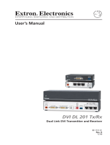
Up to 30 km (18.75 miles)
singlemode ber
SM Model
HDMI
HDMI
Audio
Output
Extron
XPA 1002
Power Amplier
Blu-Ray Player
Extron
FOXBOX Rx HDMI
Fiber Optic Receiver
Figure 1. Typical PowerCage FOX Tx/Rx HDMI Application
PowerCage FOX HDMI • Introduction 1

This guide includes instructions for an experienced installer to install, configure, and operate
the equipment.
About the PowerCage FOX HDMI Transmitters and Receivers
The PowerCage FOX HDMI Fiber Optic Extender is an ultra-high performance ber optic
transmitter and receiver set for long haul transmission of HDCP-compliant HDMI video,
audio, and RS-232 control signals over fiber optic cabling. The transmitter and receiver can
extend HDMI signals up to 30 km (18 miles).
NOTE: For HDCP compliance:
• A PowerCage FOX HDMI or FOXBOX HDMI transmitter must be paired with
a PowerCage FOX HDMI or FOXBOX HDMI receiver.
• You must connect both fiber optic cables between the transmitter and
receiver.
• A signal cannot be daisy-chained and retain HDCP compliance.
• The bidirectional Consumer Electronics Control (CEC) is not supported.
Transmitter
The PowerCage FOX Tx HDMI transmitter accepts HDMI video or DVI-D video (with an
applicable adapter), at resolutions up to 1920 x 1200 at 60 Hz. The video input can also
include embedded audio.
The transmitter can also accept an analog audio input on a 3.5 mm mini jack. An internal
DIP switch selects either the embedded audio or the separate analog audio for the unit to
transmit to the receiver.
The transmitter accepts a one-way (transmitter-to-receiver) RS-232 serial communication
signal input (projector control, for example). The transmitter can receive an optional return
(receiver-to-transmitter) stream of serial RS-232 communications (projector responses, for
example).
The transmitter converts the HDMI video, the selected audio, and the RS-232 serial
communication into a proprietary data stream and outputs it as an optical signal on a single
LC connector to a compatible fiber optic receiver. It also can receive a proprietary optical
signal from the receiver consisting of the RS-232 return from a controlled device.
Receiver
The PowerCage FOX Rx HDMI receiver accepts a proprietary optical signal on a single LC
connector from a compatible fiber optic transmitter or daisy-chained receiver and outputs a
single link of HDMI video, digital audio (embedded in the HDMI output), analog audio, and
RS-232 serial commands.
If the receiver is appropriately configured and has a second fiber optic cable installed, it also
can either:
• Receive an RS-232 return from a controlled device and send it to the transmitter via a
proprietary optical signal.
• Output a daisy-chained signal to another receiver.
If either RS-232 return or daisy-chained communications are implemented, the receiver
outputs a proprietary signal on the second fiber optic cable carrying the signal.
For video resolutions up to 1600 x 1200, 1080p, or 1920 x 1200, the video output of the
receiver is a perfect, pixel-for-pixel recreation of the video signal input to the transmitter.
PowerCage FOX HDMI • Introduction 2

With the appropriate adapter, the single link of HDMI video output by the receiver can be
converted to DVI-D video.
The receiver has built-in alternating pixels, color bars, and grayscale test patterns to assist in
setting up the display equipment.
Transmitter and receiver
The transmitter and receiver have many controls, including image and audio adjustments,
and available under RS-232 Simple Instruction Set (SIS™) control. Both units have image,
audio, and fiber light status and lost-light alarm indicators.
System Compatibility
The PowerCage FOX Tx HDMI transmitter operates in either of two modes, selected under
RS-232 control, for compatibility with other, non-HDMI, units:
• Plus — Supports resolutions up to 1920 x 1200 @ 60Hz. The ber optic output of the
transmitter can be received only by one of four receivers: a PowerCage HDMI Rx, a
PowerCage FOX DVI Plus Rx, a FOXBOX HDMI Rx, or a FOXBOX DVI Plus Rx.
• Non-plus — Supports resolutions up to 1600 x 1200 @ 60 Hz or 1080p. The ber
optic output of the transmitter can be received by any PowerCage FOX, FOXBOX, and
FOX 500 VGA, and DVI unit, including the Plus and non-Plus units.
The FOXBOX Rx HDMI receiver operates interchangeably with all PowerCage FOX, FOXBOX,
and FOX 500 VGA and DVI units, including Plus and non-Plus units.
NOTE: • Although the receiver can operate with non-HDMI transmitters, the video
output is not HDCP-compliant.
• The transmitter and receiver are not compatible with the PowerCage FOX AV,
FOX AV, PowerCage FOX 3G HD-SDI, FOX 3G HD-SDI, and FOX 3G DVC
models.
Cable Transmission Modes
The transmitter and receiver are further categorized by the type of fiber optic cable,
multimode or singlemode, which defines the effective range of transmission:
• Multimode — Long distance, up to 2 km (6,560 feet) (depending on the fiber cable)
• PowerCage FOX Tx HDMI MM
• PowerCage FOX Rx HDMI MM
• Singlemode — Very long distance, up to 30 km (18.75 miles)
• PowerCage FOX Tx HDMI SM
• PowerCage FOX Rx HDMI SM
NOTE: The multimode and singlemode units are physically and functionally identical,
with the exception of the effective range of transmission. In this guide, any
reference applies to either transmission mode unless otherwise specified.
PowerCage FOX HDMI • Introduction 3

Features
Ultra high performance — Offers pixel-for-pixel HDMI or DVI-D (with an adapter) video
transmission, up to 1920 x 1200 at 60 Hz (in plus mode) or 1600 x 1200 at 60 Hz (in
non-plus mode).
Video input — The transmitter accepts a single link of HDMI or DVI-D video.
EDID emulation mode (Display Data Channel [DDC]) — The PowerCage FOX Tx HDMI
transmitter provides a selector switch for specifying the rate of the incoming digital video
signal. EDID emulation mode allows proper operation
Video output — The receiver outputs a single link of HDMI video.
Extron fiber optic product compatibility — Enables ultra-long distance HDMI-to-analog
RGB and analog RGB-to-HDMI conversion without the need for extra signal conversion
devices.
Compatibility with FOX 500 DA6 distribution amplifier and FOX Matrix Switchers
Analog audio input — The transmitter accepts an unbalanced stereo audio input on a
3.5 mm mini jack.
Analog audio input gain/attenuation — The input audio level can be adjusted within a
range of -18 dB (attenuation) to +10 dB (gain) via the RS-232 link.
Analog audio output — The receiver outputs balanced or unbalanced stereo audio on a
3.5 mm, 5-pole captive screw terminal.
Links monitoring — The panels of the transmitters and receivers have indicators for
monitoring both fiber optic links.
Loss-of-light alarms — The rear panels of the transmitters and receivers have discrete
outputs that indicate if either of the fiber optic links has suffered a loss of the light signal.
FOX Extenders Control Program — For RS-232 remote control from a PC running
Windows
®
, the Extron FOX Extenders control software provides a graphical interface and
drag-and-drop, point-and-click operation.
Simple Instruction Set (SIS) — The transmitter and receiver use the SIS for easy remote
control operation.
Audio level — The audio output can be set to either the consumer level (-10 dBV) or
professional level (+4 dBu) under RS-232 control.
Upgradable firmware — The firmware that controls the operation of each unit can be
upgraded in the field via the Configuration port on the PowerCage enclosure without taking
the unit out of service. Firmware upgrades are available for download on the Extron website,
www.extron.com, and they can be installed using the FOX Extenders Control Program.
Memory presets — 30 memory presets let you store input size and position settings relative
to a specific input resolution. You can then recall those settings, when needed, using the SIS
or the control software.
PowerCage mounting — All PowerCage FOX Tx and Rx units are mountable in any Extron
PowerCage enclosure.
LockIt™ HDMI Cable Lacing Bracket — Each transmitter and receiver includes a LockIt
bracket to secure the HDMI cable to the unit.
PowerCage FOX HDMI • Introduction 4

Installation and
Operation
This section describes the installation and operation of the PowerCage FOX HDMI, including:
• Mounting the Units
• Rear Panel Connections, Controls, and Indications
• Transmitter Side Panel Controls
• PowerCage Front Panel Port, Control, and Indicators
• Operation
Mounting the Units
The PowerCage FOX transmitter or receiver must be installed in an Extron PowerCage
enclosure (see “Installing a Board in the Enclosure” on page 42.)
Rear Panel Connections, Controls, and Indications
PowerCage
FOX Tx HDMI
Transmitter
PowerCage
FOX Rx HDMI
Receiver
1 2
REMOTE
RS-232
RS-232
OVER FIBER
Tx Rx
Tx
ALARM
INPUT
PowerCage
FOX Tx HDMI
Tx Rx
AUDIO
HDMI
HDCP
HDMI
AUDIO
Rx
1 2
REMOTE
RS-232
RS-232
OVER FIBER
Tx Rx
Tx
ALARM
Rx
OUTPUT
PowerCage
FOX Rx HDMI
Tx Rx
LR
AUDIO
HDMI
HDCP
ON
HDMI
AUDIO
OFF
AUDIO
7
1111
6
8
10
9
55
1
2
3
3
12 12
44
Figure 2. PowerCage FOX Tx Transmitter Connectors, Controls, and Indications
a
HDMI Input connector — Connect a single link of HMI video to this
HDMI
connector. See “HDMI connectors“ on page 10 for pin assignments and to use
the LockIt HDMI Cable Lacing Bracket to secure the connector to the transmitter.
b
Audio Input connector — Connect an unbalanced stereo or mono
AUDI
O
audio input to this connector.
The input audio level can be set via RS-232 control (see “Audio Adjustment
area“ in the “Remote Control” section on page 29.
PowerCage FOX HDMI • Installation and Operation 5

c
RS-232 Over Fiber port — If you want the transmitter and receiver
RS-232
OVER FIBER
Tx Rx
system to pass serial command signals between the transmitter and receiver,
for example for serial control of a projector, connect the host device to the
transmitter and the slave device to the receiver via the leftmost three poles
on the left (Tx, Rx, and _) of the 5-pole captive screw connectors on both units (see
“RS-232 connectors“ on page 11 to wire this connector).
NOTES: • If you connect only one fiber optic cable (item
f
on page 8), or you
configure the receiver for daisy-chaining, you do not receive reports from
the controlled device. To receive responses from the controlled device,
you must install two fiber optic cables and leave link 2 enabled (via an
SIS command to the receiver or using the FOX Extenders Control
Program).
• The PowerCage FOX Extender can pass RS-232 commands and responses
at rates up to 115200 baud.
d
Remote RS-232 port — For serial control of the transmitter and receiver,
1 2
REMOTE
RS-232
Tx Rx
ALARM
connect a host device, such as a computer, to either unit via three poles
(Tx, Rx, and _) of this 5-pole captive screw connector on either unit (see
“RS-232 connectors“ on page 11 to wire this connector.)
See “Remote Control“ beginning on page 17 for definitions of the SIS commands
(serial commands to control the transmitter via this connector).
e
Alarm outputs port — For remote monitoring of the status of the
1 2
REMOTE
RS-232
Tx Rx
ALARM
Rx fiber optic link, connect a locally-constructed or furnished monitoring device
to the unit to be monitored via two poles of this 5-pole captive screw
connector on the unit to be monitored. When the unit does not detect light on
its Rx connector, pin 1 and pin 2 of this port are shorted together.
PowerCage FOX HDMI • Installation and Operation 6

f
Transmitter fiber optic connectors and LEDs —
WARNING: These units output continuous invisible light, which may be harmful to
the eyes; use with caution. For additional safety, plug the attached dust
caps into the optical transceivers when the fiber cable is unplugged.
NOTES: • Ensure that you use the proper ber cable for your transmitter and
receiver pair. Typically, singlemode fiber has a yellow jacket and
multimode cable has an orange or aqua jacket.
• Only one fiber optic cable, transmitter-Tx-to-receiver-Rx, is required for
video, audio, and serial command transmission. But, if you connect only
one fiber optic cable, or if your receiver is configured to daisy-chain the
optical signal:
• The HDMI signal output by the receiver is not HDCP-compliant.
• You do not receive RS-232 reports from the controlled device.
To receive responses from the controlled device and for HDCP
compliance, you need to install both fiber optic cables and leave link 2
enabled (via an SIS command to the receiver or using the FOX
Extenders Control Program).
ä
Tx (required) — For all one-way video, audio, and serial
communications from the transmitter to the receiver, connect a
fiber optic cable to the Tx LC connector.
Connect the free end of this fiber optic cable to the Rx connector
(item
ç
on the next page) on the PowerCage FOX Rx HDMI
receiver or to any other compatible Extron FOX device.
ã
Rx (optional) — Connect a fiber optic cable for all one-way
return serial communications from the receiver to the transmitter.
Connect the free end of this fiber optic cable to the Tx connector
(item
å
on the next page) on the PowerCage FOX Rx receiver in
normal mode or to any other compatible Extron FOX device.
Tx and Rx LEDs — When lit, the link is active (light is received).
Figure 3. One Way
Configuration
Receiver
Transmitter
6a 6b
7b 7a
Tx Rx
Tx Rx
PowerCage FOX HDMI • Installation and Operation 7

g
Receiver fiber optic connectors and LEDs —
WARNING: These units output continuous invisible light, which may be harmful to
the eyes; use with caution. For additional safety, plug the attached dust
caps into the optical transceivers when the fiber cable is unplugged.
NOTES: • You can connect the transmitter to one or more receivers in one of three
ways:
• One way (transmitter to receiver) only — Connect a fiber cable
to connector
å
from transmitter connector
ä
only (see figure 3).
• Two way (transmitter to receiver and return) — Connect a fiber
cable to connector
å
from transmitter connector
ä
and a fiber cable
from connector
ç
back to the transmitter connector
ã
(see figure 4.)
• One way (transmitter to receiver) with daisy
chain (receiver to receiver) — Connect a fiber
cable from a fiber optic source to connector
å
and another cable from connector
ç
to
connector
å
on the the next receiver in the daisy
chain (see figure 5.) Set each receiver in the daisy
chain to daisy chain mode (via an SIS command
for the PowerCage FOX Rx receiver.) Up to 10
properly-configured receivers can be connected
in a daisy chain to a single transmitter.
• See the transmitter fiber connector NOTES on the
previous page, which also apply to these connectors.
From Transmitter
or Daisy-Chained
Receiver
Receiver
Receiver
7b
7a
7a
Tx Rx
Tx Rx
Figure 5. Daisy Chain Configuration
å
Rx (required) — For all one-way video, audio, and serial communications from
the transmitter to the receiver, connect a fiber optic cable to the Rx LC connector.
Connect the free end of this fiber optic cable to the Tx connector on the
PowerCage FOX Tx transmitter (item
ä
on the previous page) or to any other
compatible Extron ber optic device.
ç
Tx (optional) — Connect a fiber optic cable to the Tx LC connector for either of
the following functions:
Normal configuration — For all one-way return serial communications from the
receiver to the Rx connector on the transmitter (see figure 5.)
Daisy chain configuration — For daisy-chained video, audio, and serial
communications to the Rx connector on another receiver (see figure 6.)
NOTE: The Tx connector emits light in either case and the Rx port receives light.
Connect the free end of this fiber optic cable to either:
• The Rx connector on the PowerCage FOX Tx transmitter (item
ã
on the
previous page) or to any other compatible Extron ber optic device
• The Rx connector on another receiver in the daisy chain.
Tx and Rx LEDs — When lit, the link is active (light is received).
Figure 4. Two Way
Configuration
Transmitter
(page 7) (page 7)
Receiver
7b 7a
6a 6b
Tx Rx
Tx Rx
PowerCage FOX HDMI • Installation and Operation 8

h
HDMI output connector — Connect a video display to this HDMI connector .
HDMI
See “HDMI connectors“ on the next page for pin assignments and to use the
LockIt HDMI Cable Lacing Bracket to secure the connector to the receiver.
i
Audio output connector (receivers) — This 5-pole, 3.5 mm captive
LR
AUDIO
screw connector outputs the transmitted, unamplified, line level audio.
Connect audio devices, such as an audio amplifier or powered speakers. See
“Audio output connector“ on page 12 to wire a captive screw connector
for the appropriate output type and impedance level.
j
Audio switch — This switch mutes (Off) and unmutes (On) the embedded audio
ON
AUDIO
OFF
output on the HDMI output connector. The audio on the captive screw audio
output always remains active regardless of the setting of this switch.
k
Signal LEDs — These indicators light when the transmitter or receiver senses
HDMI
HDCP
AUDIO
that the associated signal is input (transmitter) or received on the fiber optic
cable (receiver).
• HDMI — The unit is sensing an HDMI input signal.
• HDCP — The input signal is HDCP encrypted.
• Audio — The unit is sensing an audio input signal above –35 dBV. The LED turns off
if the audio signal level drops below the threshold for 10 seconds.
l
Power LED — This LED lights to indicate that power is applied to the unit through the
PowerCage backplane.
PowerCage FOX HDMI • Installation and Operation 9

Making Connections
HDMI connectors
Figure 6 denes the pinout for the HDMI protocol.
Pin Signal
1
TMDS data 2+
TMDS data 2-
TMDS data 0–
TMDS clock- +5 V power
Hot plug detect
CEC control
Reserved
(NC)
TMDS data 1+ TMDS clock+
TMDS clock
shield
SDA
DDC / CEC
Ground
TMDS data 2
shield
Pin Pin Signal Signal
2
71
3
41
01
6
11 17
12 18
19
14
3
TMDS data 0-
TMDS data 0
shield
8
9
SCL
15
TMDS data 1-
TMDS data 1
shield
5
6
HDMI
HDMI
Type A Receptacle
Type A Plug
1
18 2
19
1
182
19
Figure 6. HDMI Connector
HDMI signals run at a very high frequency and are especially prone to errors caused by bad
video connections, too many adapters, or excessive cable length. To avoid the loss of an
image or jitter, follow these guidelines:
• Do not exceed 16.4 feet (5 meters) on the input of the PowerCage FOX HDMI
transmitter or the output of the PowerCage FOX HDMI receiver.
• Use only the cable designed for HDMI signals that is supplied by Extron.
• Limit or avoid the use of adapters.
• Use only cables specically intended for HDMI or DVI signals. Use of non-HDMI or
non-DVI cables or modied cables can result in a missing video output.
To securely fasten an HDMI cable to a device:
1. Plug the HDMI cable into the panel connection (see
a
in figure 7).
3
3
1
2
4
5
Figure 7. Installing the LockIt Lacing Bracket
2. Loosen the HDMI connection mounting screw from the panel enough to allow the
LockIt lacing bracket to be placed over it (
b
). The screw does not have to be removed.
PowerCage FOX HDMI • Installation and Operation 10

3. Place the LockIt lacing bracket on the screw and against the HDMI connector, then
tighten the screw to secure the bracket (
c
).
ATTENTION: Do not overtighten the HDMI connector mounting screw. The shield
to which it fastens is very thin and can easily be stripped.
4. Loosely place the included tie wrap around the HDMI connector and the LockIt lacing
bracket as shown (
d
).
5. While holding the connector securely against the lacing bracket, use pliers or a similar
tool to tighten the tie wrap, then remove any excess length (
e
).
RS-232 connectors
The RS-232 Over Fiber port is for transmission of serial signals, such as projector control
signals, between the transmitter and receiver.
The Remote RS-232 port is for remote control of the transmitter and receiver. The protocol
for the Remote RS-232 port is as follows:
• 9600 baud • no parity • 8 data bits
• 1 stop bit • no ow control
Do not tin the wires!
Controlling
Device
Ground ( )
Receive (Rx)
Transmit (Tx)
Ground ( )
Receive (Rx)
Transmit (Tx)
Bidirectional
FunctionPin
Tx
Rx
Gnd
Transmit data
Receive data
Signal ground
RS-232
OVER FIBER
Tx Rx
1 2
REMOTE
RS-232
Tx Rx
ALARM
NOTE: Cross the Tx and Rx lines once between
the source and the target.
Figure 8. RS-232 Over Fiber Connector
NOTE: The length of exposed wires is critical. The ideal length is 3/16 inch (5 mm).
• Longer bare wires can short together.
• Shorter wires are not as secure in the connectors and could be pulled out.
PowerCage FOX HDMI • Installation and Operation 11

Alarm outputs connectors
Pin 1 and pin 2 are
shorted together when
no light is detected.
Do not tin the wires!
1 2
REMOTE
RS-232
Tx Rx
ALARM
Figure 9. Alarm Connector
NOTE: The length of exposed wires is critical (see the RS-232 connectors NOTE on the
previous page).
Audio output connector
See figure 10 to properly wire a captive screw output connector. The connector is included
with transmitter, but you must supply the audio cable. Use the supplied tie-wrap to strap the
audio cable to the extended tail of the connector.
Unbalanced Stereo Output Balanced Stereo Output
Do not tin the wires!
Tip
NO GROUND HERE
NO GROUND HERE
Tip
LR
Sleeves
Tip
Ring
Tip
Ring
LR
Figure 10. Captive Screw Connector Wiring for Stereo Audio Output
ATTENTION: For unbalanced audio, connect the sleeves to the ground contact.
DO NOT connect the sleeves to the negative (-) contacts.
NOTE: The length of exposed wires is critical (see the RS-232 connectors NOTE on
the previous page).
PowerCage FOX HDMI • Installation and Operation 12

Transmitter Side Panel Controls
The following features are on the PowerCage HDMI Tx transmitter, and are accessible
though the cut on the left side of the module enclosure (see figure 11).
1 2
2
1
Figure 11. Transmitter Side Panel Controls
a
DIP switches —
• Switch 2 (Audio) — This switch selects which audio input, the audio embedded
in the HDMI input or the analog audio, is sent to the receiver. On (left) selects the
digital (embedded) audio and off (right) selects the analog audio.
• Switch 1 (50 Hz or 60 Hz) — This switch selects the vertical refresh rate of the
resolution selected by the EDID Minder hex switch (item
b
). On (left) selects the
50 Hz rate and off (right) selects the 60 Hz refresh rate.
b
EDID Minder hex switch — Set this switch to one of the positions below to select
the source of the DDC or a specific resolution.
• Position 0 — Not applicable
• Position 1 — The EDID is selected via one of the serial ports in the system using an
SIS command or the FOX Extenders Control Program.
• Position 2 - F — Specify a resolution. The table below identifies the switch
positions and the associated resolutions.
Pos. Source or resolution Pos. Resolution Pos. Resolution
0 Not applicable 6 1280 x 800 C 1600 x 1200
1 RS-232 7 1280 x 1024 D 1680 x 1050
2 800 x 600 8 1360 x 768 E 1920 x 1080 (1080p)
3 1024 x 768 9 1366 x 768 F 1920 x 1200
4 1280 x 720 (720p) A 1400 x 1050
5 1280 x 768 B 1440 x 900
PowerCage FOX HDMI • Installation and Operation 13

PowerCage Front Panel Port, Control, and Indicators
The following features are on the front panel of the PowerCage enclosure (see figure 12).
PowerCage 1600
COMM
1
POWER
ALARM
2 3 14 15 16
1
PSU
2
PSU
1
FAN
2
FAN
COMM
SELECT
CONFIG
TEMP
2 3 6541
Figure 12. PowerCage Front Panel Features
a
Comm LED (16 board locations) — This LED lights to indicate that the board at this
location is selected for connection to the Configuration port (item
e
). Repeatedly press
the Comm Select button (item
d
) as necessary to select the desired board.
b
Power LED (all locations) — This LED lights to indicate that power is applied to the
device at this location.
c
Alarm LED (16 board locations) — This LED lights to indicate that light is not received
on the Rx connector of the board at this location.
Alarm LED (2 PS locations) — This LED lights to indicate that the power supply has failed
or is out of tolerance.
Alarm LED (2 Fan locations) — This LED lights to indicate that the fan has failed.
PowerCage FOX HDMI • Installation and Operation 14
/