Page is loading ...

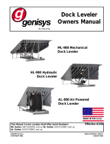
HL-900
Dock Leveler
Owners Manual
This Manual Covers Dock Levelers Built After Serial Numbers:
13GD480708M and up
PRINTED IN U.S.A.
RITE-HITE PRINT SHOP
PUBLICATION NO. 1213
APRIL 2016
part of the SMOOTH TRANSITION DOK SYSTEMTM
By Rite-Hite
MADE IN U.S.A.

2Pub. No. 1213 - April 2016
Genisys HL-900 Dock Leveler Owner’s Manual
NOTES

Pub. No. 1213 - April 2016 3
Genisys HL-900 Dock Leveler Owner’s Manual
TABLE OF CONTENTS
NOTICE TO USER . . . . . . . . . . . . . . . . . . . . . . . . . . . . . . . . . . . . . . . . . . . . . . . . . . . . . . . . . . . . . . . . . . . . . . . . . . . . . . . . . . . . . . . . . . . . . .3
SAFETY WARNINGS . . . . . . . . . . . . . . . . . . . . . . . . . . . . . . . . . . . . . . . . . . . . . . . . . . . . . . . . . . . . . . . . . . . . . . . . . . . . . . . . . . . . . . . . . . . .4
OWNER RESPONSIBILITY . . . . . . . . . . . . . . . . . . . . . . . . . . . . . . . . . . . . . . . . . . . . . . . . . . . . . . . . . . . . . . . . . . . . . . . . . . . . . . . . . . . . . . .7
OPERATION INSTRUCTIONS . . . . . . . . . . . . . . . . . . . . . . . . . . . . . . . . . . . . . . . . . . . . . . . . . . . . . . . . . . . . . . . . . . . . . . . . . . . . . . . . . . . . .8
MAINTENANCE PROCEDURES . . . . . . . . . . . . . . . . . . . . . . . . . . . . . . . . . . . . . . . . . . . . . . . . . . . . . . . . . . . . . . . . . . . . . . . . . . . . . . . . . .10
HYDRAULIC LEVELER ADJUSTMENTS/TROUBLESHOOTING . . . . . . . . . . . . . . . . . . . . . . . . . . . . . . . . . . . . . . . . . . . . . . . . . . . . . . . .12
HYDRAULIC LEVELER - HYDRAULIC SCHEMATIC . . . . . . . . . . . . . . . . . . . . . . . . . . . . . . . . . . . . . . . . . . . . . . . . . . . . . . . . . . . . . . . . . .18
ELECTRICAL WIRING CHARTS . . . . . . . . . . . . . . . . . . . . . . . . . . . . . . . . . . . . . . . . . . . . . . . . . . . . . . . . . . . . . . . . . . . . . . . . . . . . . . . . .21
ELECTRICAL SCHEMATICS . . . . . . . . . . . . . . . . . . . . . . . . . . . . . . . . . . . . . . . . . . . . . . . . . . . . . . . . . . . . . . . . . . . . . . . . . . . . . . . . . . . . .22
REPLACEMENT PARTS . . . . . . . . . . . . . . . . . . . . . . . . . . . . . . . . . . . . . . . . . . . . . . . . . . . . . . . . . . . . . . . . . . . . . . . . . . . . . . . . . . . . . . . .30
WARRANTY . . . . . . . . . . . . . . . . . . . . . . . . . . . . . . . . . . . . . . . . . . . . . . . . . . . . . . . . . . . . . . . . . . . . . . . . . . . . . . . . . . . . . . . .BACK COVER
PRODUCT SPECIFIC WARRANTY
Rite-Hite®warrants the HL9 Dock Leveler for one-year parts and labor from date of shipment in accordance with Rite-Hite's Standard Warranty
Policy.
NOTICE TO USER
Your local Rite-Hite®representative provides a Planned Maintenance Program (P.M.P.) which can be fitted to your specific operation. Call
your local representative or Rite-Hite®at 414-355-2600.
The Rite-Hite products in this manual are covered by one or more of the following U.S. patents: 5882167, 6065172, 6070283, 6085375,
6092970, 6106212, 6116839, 6190109, 6276016, 6311352, 6318947, 6322310, 6360394, 6368043, 6431819, 6488464, 6524053, 6726432,
6773221, 6832403, 6880301, 7032267, 7062814, 7213285, 7216391, 7363670, 7380305, 7503089, 7533431, 7546655, 7584517, 7681271,
7823239, 7841823, 7877831, 7914042, 8006811, 8065770, 8141189, 8191194, 8286757, 8287223, 8303235, 8307956, 8443474, 8464384,
8464846, 8465245, 8497761, 8499897, 8544130, 8547234, 8590087, 8590673, 8616826, 8657551, 8662535, 8678736, 8690087, 8905198,
9010501, 9096170, 9096397, 9126775, 9139384, 9145273, 9150367, 9174811, 9227799, 9230419 and pending U.S and foreign patent
applications. RITE-HITE®, THINMANTM, SAFE-T-LIP®, HYDRACHEK®, WHEEL-LOKTM, DOK-LOK®, DUAL-DOK®, SAFE-T-STRUTTM,
DOK-COMMANDER®, JUMBOTM, HYDRA-RITETM, SAFE-T-GATE®, RITE-VUTM LIGHT COMMUNICATION SYSTEM and SMOOTH TRANSITION
DOK SYSTEMTM, are trademarks of Rite-Hite®.

4Pub. No. 1213 - April 2016
Genisys HL-900 Dock Leveler Owner’s Manual
SAFETY WARNING
LOCKOUT/TAGOUT PROCEDURES
The Occupational Safety and Health Administration (OSHA) requires, in addition to posting safety warnings and barricading the work area
(including, but not limited to, trucking office and loading docks), that the power supply has been locked in the OFF position or disconnected. It is
mandatory that an approved lockout device is utilized. An example of a lockout device is illustrated. The proper lockout procedure requires that
the person responsible for the repairs is the only person who has the ability to remove the lockout device.
In addition to the lockout device, it is also a requirement to tag the power control in a manner that will clearly note that repairs are under way
and state who is responsible for the lockout condition. Tagout devices have to be constructed and printed so that exposure to weather condi-
tions, or wet and damp locations, will not cause the tag to deteriorate or become unreadable.
RITE-HITE®does not recommend any particular lockout device, but recommends the utilization of an OSHA approved device (refer to OSHA
regulation 1910.147). RITE-HITE®also recommends the review and implementation of an entire safety program for the Control of Hazardous
Energy (Lockout/Tagout). These regulations are available through OSHA publication 3120.
When working with electrical or electronic controls, make
sure that the power source has been locked out and
tagged out according to OSHA regulations and approved
local electrical codes.
DO NOT
OPERATE
This is a statement of serious hazard. Failure to follow the
listed instructions could place the individual at risk of
serious injury or death.
This is the highest level statement. Failure to follow the
listed instructions will most likely result in severe injury
or death.
The statements used with this level of warning deal with a
safe operating procedure. If the procedure is ignored the
possibility of personal injury may exist.
IMPORTANT is used to draw attention to a procedure that
needs to be followed to prevent machine damage.

Pub. No. 1213 - April 2016 5
Genisys HL-900 Dock Leveler Owner’s Manual
OTHER IMPORTANT OPERATIONAL SAFETY WARNINGS
Never be under the dock leveler platform or lip without:
• Installing the Safe-T-StrutTM or other supporting device.
• If lip needs to be extended, follow procedures shown
under Safety Devices on the following page.
• Turning off power to the control box.
• Locking out and tagging out the main power source, as
shown under Safety Warnings on preceding page.
Always barricade the dock leveler at ground level and
dock level from any form of traffic when maintenance is
required.
Inspect the dock leveler monthly to ensure that there are
no broken or worn parts which could cause injury to
personnel or damage to the equipment.
• Before starting installation or maintenance, check and
follow the safety procedures of the facility where the
dock leveler is being installed.
• Never enter a truck/trailer until its brakes are set, air
has been dumped from air ride suspension
(if applicable), and you have visually inspected to be
sure truck/trailer is securely held in place by a vehicle
restraint or wheel chock per OSHA regulations.
• Never operate the leveler with you, anyone, or anything
on, or in front of the leveler, or without a truck/trailer
parked in position, or from on the truck/trailer bed.
• DO NOT operate with anyone under platform or in front
of the lip.
• When leveler is not in use, always store it so that it is
supported by the lip supports and that it is level with
the surrounding dock floor.
• If a malfunction does occur, always call your
authorized RITE-HITE®service representative
immediately.

6Pub. No. 1213 - April 2016
Genisys HL-900 Dock Leveler Owner’s Manual
SAFETY DEVICES
Never be under the dock leveler platform or lip without:
• Installing the Maintenance Strut. See below right. This
can be done with the assistance of another person by:
- Raise leveler until platform reaches its highest
position and lip extends. Continue to maintain this
position.
- Then have assistant insert the Maintenance Strut
over the base located on the leveler’s front frame.
- Release the pushbutton on powered levelers
allowing the support to rest inside the lip cup on
the underside of the lip.
• Lockout/Tagout power supply.
- Turn off the power to the control box.
- Lockout/tagout the main power source, as shown
under Safety Warnings on the inside front cover of
this manual.
- Always barricade the leveler at dock level and drive
level to prevent any unauthorized use of the leveler.
Remove the Maintenance Strut.
• For Maintenance Strut removal, have an assistant raise
the leveler to its highest position with lip fully
extended. Lift the support off base. Return the
Maintenance Strut to the proper storage position.
• If you are unable to install the Maintenance Strut
properly, contact your authorized RITE-HITE® Service
Representative or RITE-HITE® Customer Service at
1-414-355-2600.
• Post warnings and barricades at dock level and at
drive level to indicate that work is being done around
and under the leveler platform.
• Lockout/Tagout power to the leveler and post warnings
when work is being performed on the leveler.
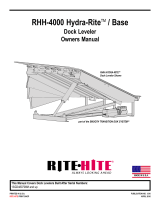
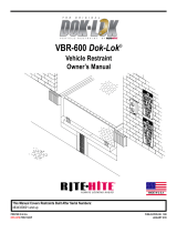
FIGURE 2 - INSTALL MAINTENANCE STRUT
INSERT INTO CUP
INSERT
ONTO BASE

Pub. No. 1213 - April 2016 7
Genisys HL-900 Dock Leveler Owner’s Manual
OWNER RESPONSIBILITY
1. The owner should recognize the inherent danger of the
interface between dock and transport vehicle. The owner
should, therefore, train and instruct operators in the safe use
of dock equipment in accordance with the information
provided below. The manufacturer shall publish, provide to the
initial purchaser, and make the following information readily
available to owners:
•Installation instructions
•Recommended initial and periodic inspections procedures
•Maintenance procedures
•Operating instructions
•Descriptions or specifications for replaceable or repairable
parts
•Tables identifying the grade (slope) for all variations of
length or configuration of the dock equipment, and
•Information identifying the maximum uncontrolled drop
encountered upon sudden removal of support while within
the working range of the equipment.
It shall be the responsibility of the owner to verify that the
material listed in this section has been received and that it is
made available for the instruction and training of presonnel
entrusted with the use or maintenance of the dock equipment.
2. When a transport vehicle is parked at a loading dock, it is
important that the vehicle is relatively perpendicular to the
dock face and in close contact with at least one of the dock
bumpers.
3. Nameplates, cautions, instructions, and posted warnings shall
not be obscured from the view of operating or maintenance
personnel for whom such warnings are intended.
4. Manufacturer’s recommended periodic maintenance and
inspection procedures in effect at date of shipment shall be
followed, and written records of the performance of these
procedures should be kept.
5. As with any piece of machinery, dock equipment requires routine
maintenance, lubrication, and adjustments. Your local
RITE-HITE®representative offers owners the option of a
Planned Maintenance Program (P.M.P.). As part of this
service, your local RITE-HITE®representative will do all
routine maintenance, lubrication, and adjustments.
6. Dock equipment that is structurally damaged shall be removed
from service, inspected by a manufacturer’s authorized
representative, and repaired as needed before being placed
back in service.
7. The manufacturer shall make available replacement
nameplates, caution/instruction labels, and operating /
maintenance manuals upon request of the owner. The owner
shall see that all nameplates, caution/instruction markings or
labels are in place and legible, and that the appropriate
operating/maintenance manuals are provided to users.
8. Modifications or alterations of dock equipment shall be made
only with written permission of the original manufacturer.
These changes shall also satisfy all safety recommendations
of the original equipment manufacturer for the particular
application of the dock equipment.
9. In order to be entitled to the benefits of the standard product
warranty, the dock equipment must have been properly
installed, maintained and operated within its rated capacities
and/or specific design parameters, and not otherwise abused.
10. It is recommended that trailers equipped with air ride
suspensions should remove the air from the suspension to
minimize trailer bed drop, prior to loading or unloading.
11. When industrial trucks are driven on and off transport vehicles
during the loading and unloading operation, the brakes on the
transport vehicle shall be applied and wheel chocks or a
positive restraining device shall be engaged.
12. In selecting dock equipment, it is important to consider not
only present requirements but also future plans or adverse
environments.

8Pub. No. 1213 - April 2016
Genisys HL-900 Dock Leveler Owner’s Manual
NORMAL OPERATION
1. Activate the leveler by pushing and holding the RAISE button
until leveler is fully raised and lip is fully extended. See figure 3.
NOTE: Some levelers may be equipped with a two button control
box. If so, push and hold the RAISE button to raise the platform.
While pressing the RAISE button, push the LIP EXTEND button
to fully extend the lip when the lip has cleared trailer bed.
2. When lip is fully extended, release RAISE button. The leveler will
automatically lower onto the truck/trailer bed. See figure 4.
NOTES:
a. Some levelers may be equipped with a two button control box. If
so, release RAISE and LIP EXTEND buttons.
b. Be sure the lip is in full contact with the truck/trailer bed before
loading or unloading truck/trailer.
3. See Storing Leveler.
NOTES:
a. Levelers without Automatic Return to Dock (ARTD) If the
truck/trailer departs, the leveler will move to its lowest position
and the lip will fall to the pendant position inside the dock
bumpers. See Storing Leveler.
b. Levelers with Automatic Return to Dock (ARTD) If the lip is on
the truck/trailer and the truck departs, the leveler will move to its
lowest position and the lip will begin to lower. As the lip drops
toward the pendant position, the ARTD system automatically
returns the leveler to the stored position without operator
assistance.
BELOW DOCK LOADING OPERATION
1. Activate the leveler by pushing and holding the RAISE button
until leveler is fully raised and lip is fully extended. See figure 3.
NOTE: Some levelers may be equipped with a two button control
box. If so, push and hold the RAISE button to raise the platform.
While pressing the RAISE button, push the LIP EXTEND button
to fully extend the lip when the lip has cleared trailer bed.
2. When lip is fully extended, release RAISE button.
NOTE: Some levelers may be equipped with a two button control
box. If so, release RAISE and LIP EXTEND buttons.
3. When loading/unloading is complete, continue with normal
operation or return the leveler to stored position. See Storing
Leveler.
OPERATION INSTRUCTIONS
FIGURE 3 - POWERED DOCK LEVELER
FIGURE 4 - NORMAL OPERATION

Pub. No. 1213 - April 2016 9
Genisys HL-900 Dock Leveler Owner’s Manual
DOCK LEVEL (OR LOWER) END LOADING
OPERATION
1. Activate the leveler by pushing and holding the RAISE button
until leveler is fully raised and lip begins to extend. See figure 5.
NOTE: Some levelers may be equipped with a two button control
box. If so, push and hold the RAISE button until the lip clears the
lip supports. While pressing the RAISE button, push the LIP
EXTEND button briefly to extend the lip beyond the lip supports.
2. When lip extends about 2 inches, release RAISE button. See
figure 5. The leveler will lower to the below dock position with the
lip positioned between the face of the loading dock and the
truck/trailer bed. See figure 6.
NOTES:
a. Some levelers may be equipped with a two button control box. If
so, release RAISE and LIP EXTEND buttons
b. End load at dock level and above can be handled with the leveler
in its stored position on units without a Safe-T-Lip®.
c. If the lip extended too far, quickly push and release the RAISE
button to slightly retract the lip.
d. If the lip was not extended far enough and hits the lip supports,
repeat this step allowing the lip to extend farther.
3. When loading/unloading is complete, continue with normal
operation or return the leveler to stored position. See Storing
Leveler.
STORING LEVELER
1. To store the leveler, push and hold the RAISE button until leveler
is about 6 inches above dock level and lip is fully pendant.
2. Release RAISE button. Leveler will lower to dock level with lip
resting in the lip supports. See figure 7.
NOTE: On Powered levelers with Automatic Return to Dock
(ARTD). If the lip is on the truck/trailer and the truck departs, the
leveler will move to its lowest position and the lip will begin to
lower. As the lip drops toward the pendant position, the ARTD
system automatically returns the leveler to the stored position
without operator assistance.
OPERATION INSTRUCTIONS CONT.
FIGURE 6 - END LOAD OPERATION
FIGURE 5 - END LOAD OPERATION - LIP POSITION
FIGURE 7 - LEVELER STORED

10 Pub. No. 1213 - April 2016
Genisys HL-900 Dock Leveler Owner’s Manual
MAINTENANCE PROCEDURES
SUGGESTED LEVELER MAINTENANCE
NOTE: Follow maintenance procedures below as outlined.
Include the specific steps for your leveler model.
NOTE: Your local RITE-HITE®representative provides a Planned
Maintenance Program (P.M.P.) which can be fitted to your
specific operation. Call your local representative.
Daily
1. Remove debris on and around leveler. Be sure the hinge section
of the lip and the platform is clean.
2. Check unit for proper operation.
90 Days
1. Perform all Daily Maintenance.
2. Clean pit.
3. Inspect hydraulic system (cylinders, hoses, fittings, and power
unit).
4. Lubricate the leveler with the proper lubricants. See figure 8.
5. Inspect all weather seals (if installed) and replace if worn or
damaged.
6. Inspect dock bumpers. Four inches (4") of bumper protection is
required. Worn, torn, loose or missing bumpers must be
replaced.
7. Check conditions of concrete, angles and welds. Repair or
replace if necessary.
8. Inspect structure, hinge pins, clevis pins and cotter pins for
abnormal wear.
9. Inspect all conduit boxes, control boxes and electrical
connections for damage. Repair or replace if worn or damaged.
NOTE: If control box has evidence of condensation.
a. Inspect conduit. Conduit should be routed to enter through
the bottom or side of the enclosure. A drip leg may be
needed if the conduit is filling with water.
b.Inspect the seal on the cover of the enclosure. The seal
should be securely adhered to the cover with no signs of
peeling or bubbling. Repair or replace if worn or damaged.
c. For non-metalic enclosures, breather vent part number
122130 may be installed. The vent is NEMA 4X and will not
change the enviromental rating of the control box.
10. With the leveler supported by the Maintenance Strut, check
hydraulic fluid level in tank. Add fluid if necessary. Use only
Rite-Hite approved hydraulic fluids.
STANDARD: 108303 - Mil 5606 Fluid (quart/red in color)
OPTIONAL: 119181 - Rite-Hite Biodegradeable Fluid (quart/light
blue in color)
360 Days
1. Perform Daily and 90-Day Maintenance.
2. Check and tighten control box mounting hardware.
Read and obey these instructions to prevent personal
injury.
• Post safety warnings and barricade work area, at dock
level and at ground level, to prevent unauthorized use
of the dock position before maintenance has been
completed.
• Make sure to install the Maintenance Strut before
proceeding with any repair work.

Pub. No. 1213 - April 2016 11
Genisys HL-900 Dock Leveler Owner’s Manual
MAINTENANCE PROCEDURES
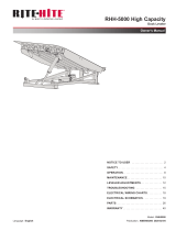
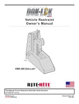
FIGURE 8 - HYDRAULIC POWERED LEVELER LUBRICATION
OIL SAE 30 Weight
NOTE:
Check Hydraulic Fluid level.

12 Pub. No. 1213 - April 2016
Genisys HL-900 Dock Leveler Owner’s Manual
LEVELER ADJUSTMENTS
HYDRAULIC LEVELER ADJUSTMENTS
NOTE:
The adjustments listed below are factory averages, field
adjustment may be necessary. None of the adjustments will
change the operating speed of the hydraulic dock leveler.
LIP STOP BOLT:
The lip stop bolt adjusts the position of the lip when the leveler is
stored. The lip stop bolt is factory adjusted on units with 16" and
18" lips, to allow the lip to be centered on lip supports when
stored. See figure 9.
OPTIONAL ARTD ADJUSTMENTS:
ARTD Limit Switch Cam
NOTE: Before continuing be sure the lip stop bolt is properly
adjusted. See figure 9.
1. Raise leveler and install a strut securely behind the header or
mini-header to allow the lip to hang pendant and rest against the
lip stop bolt.
2. Adjust ARTD Cam.
a. Adjust collars so the front edge of ARTD cam is 1/16” behind the
centerline of the ARTD limit switch. See figure 10.
b. Tighten front collar while holding the 1/16” adjustment.
c. Push the rear collar forward as much as possible and tighten.
ARTD cam assembly should rotate freely.
3. Run the leveler to test the adjustment. Verify that the lip falls a
minimum of 4” before ARTD is initiated. If not, move the cam
forward slightly.
NOTE: It is not recommended to position the ARTD cam in front
of the ARTD limit switch centerline.
7/8”
Ref.
C
1/16” ARTD
Limit Switch
Rear
Collar
ARTD Cam
Front Washer
Front Collar
NOTE: There Should Be A Small Amount Of Free Movement
Between The ARTD Cam And The Rear Collar When
The Rear Collar Is Pushed Against The ARTD Cam.
This Edge Of Cam
To Be Positioned
1/16” Behind The
Center Of Roller
As Shown.
ARTD Cam Adjustment Detail
(Shown With Lip Pendant And Lip Stop Bolt Adjusted)
L
10 - ARTD CAM ADJUSTMENT
Lip
Stop Bolt
Lip
Centered In
Keepers
FIGURE 9 - LIP STOP BOLT

Pub. No. 1213 - April 2016 13
Genisys HL-900 Dock Leveler Owner’s Manual
LEVELER ADJUSTMENTS CONT.
HYDRAULIC VALVE ADJUSTMENTS (HALDEX
POWER UNIT)
SHUTTLE VALVE ADJUSTMENT
(CONTROLS LEVELER DESCENT)
Note:
• Check oil level before making any adjustments.
1. Leveler must be adjusted to lower, from full raised position with
lip extended to the header stops, in 8 to 12 seconds.
2. Remove protective cap and O-ring. Loosen locknut; without
turning valve body or adjustment screw. Turn adjustment screw
to vary platform lowering speed. See Figure 11.
3. Adjustments should be no more than 1/8 turn increments.
4. Loosen adjustment screw to decrease platform speed while
lowering (excessive loosening can eliminate platform lowering).
5. Tighten adjustment screw to increase platform speed while
lowering (velocity fuse may lock-up as a result of increased
platform speeds while lowering).
6. Tighten locknut without turning valve body or adjustment screw.
7. Reinstall o-ring and protective cap and tighten cap.
8. Re-test the unit several times to verify the setting.
•DO NOT operate leveler with anyone standing on or in front of
the lip.
•NEVER go under the hydraulic leveler platform or lip without
installing the Maintenance Strut.
•Make sure that the leveler power is locked out and tagged out
according to OSHA regulations and approved local codes.
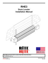
FIGURE 11 - HALDEX POWER UNIT END HEAD
•Shuttle valve is factory adjusted and sealed.
•Adjustments to be completed by trained technician only.
Ramp Cylinder Port
Lip Cylinder
Port
Adjustable
Sequence
Valve
Pilot
Operated Check
Valve
Pilot To Close
Check Valve
System
Relief
Valve
Adjustable
Shuttle
Valve
Optional Infinite Lip
Control (IFC),
Emergency Stop (ESB)
Port

14 Pub. No. 1213 - April 2016
Genisys HL-900 Dock Leveler Owner’s Manual
LEVELER ADJUSTMENTS CONT.
SEQUENCE VALVE ADJUSTMENT
(CONTROLS LIP EXTENSION)
Note:
• Check oil level before making any adjustments.
• Sequence valve is factory sealed. Adjustments to be completed
by trained technician only.
1. When the leveler is fully raised and the lip does not extend, the
Sequence Valve is set too high.
2. Remove protective cap and O-ring. Loosen locknut without
turning valve body or adjustment screw. Turn adjustment screw
counterclockwise to lower the valve pressure setting.
Note: Valve is factory set at 0.70".
3. Adjustments should be no more than 1/8 turn increments.
4. Tighten locknut without turning valve body or adjustment screw.
5. Reinstall O-ring and protective cap and tighten cap.
6. Re-test the unit several times to verify the setting.
7. If the lip begins to extend at any time before the platform has
fully raised, the Sequence Valve setting is too low.
8. Remove protective cap and O-ring. Loosen locknut without
turning valve body or adjustment screw. Turn adjustment screw
clockwise to increase the valve pressure setting.
9. Adjustments should be no more than 1/8 turn increments.
10. Tighten locknut without turning valve body or adjustment screw.
11. Reinstall O-ring and protective cap and tighten cap.
12. Re-test the unit several times to verify the setting.

Pub. No. 1213 - April 2016 15
Genisys HL-900 Dock Leveler Owner’s Manual
LEVELER ADJUSTMENTS CONT.
HYDRAULIC VALVE ADJUSTMENTS (BUCHER
POWER UNIT)
FLOW CONTROL VALVE ADJUSTMENT
(Controls Leveler Descent)
NOTE: Check oil level before making any adjustments.
1. Leveler must be adjusted to lower, from full raised position with
lip extended to the header stops in the proper time frame. See
below
HL9 8 to 12 seconds
2. Press RAISE button and run the platform up until the lip extends.
3. Release RAISE button and allow the platform to fall completely
below dock and stop. Verify with a stop watch that the platform
falls according to the times in step 1. If not, readjust flow control
valve.
4. Set flow control valve (first loosen locknut on valve). See
Figure 12.
- To fall slower - Turn in (clockwise) in 1/4 turn increments.
- To fall faster - Turn out (counter-clockwise) in 1/4 turn
increments.
Or set valve at starting point (3-1/2 turns clockwise from fully
out).
5. Repeat procedure to verify fall time as needed to fall according to
step 1. 1/8 turns might be necessary to fine tune the adjustment.
6. Tighten locknut on flow control valve.
•DO NOT operate leveler with anyone standing on or in front of
the lip.
•NEVER go under the hydraulic leveler platform or lip without
installing the Maintenance Strut.
•Make sure that the leveler power is locked out and tagged out
according to OSHA regulations and approved local codes.
•Flow Control valve is factory adjusted.
•Adjustments to be completed by trained technician only.
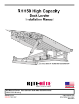
FIGURE 12 - BUCHER POWER UNIT END HEAD (HL9)
To Ramp
Cylinder
To Lip Cylinder
Sequence
Valve
Lip
Pilot To Open
Check Valve (3:1)
Lip
Pilot To Close
Check Valve (8:1)
System Relief Valve
(Set at 1,250 PSI. Do NOT adjust
without permission from Rite-Hite)
Flow Control
Valve
IFC/ESB
Option
Port
Lock Nut
Ramp
Pilot To Close
Check Valve (3:1)
HL9
SHOWN

16 Pub. No. 1213 - April 2016
Genisys HL-900 Dock Leveler Owner’s Manual
LEVELER ADJUSTMENTS CONT.
SEQUENCE VALVE ADJUSTMENT
(Controls Lip Extension)
NOTE: Check oil level before making any adjustments.
NOTE: Sequence valve is factory set. Adjustments to be
completed by trained technician only.
1. When the leveler is fully raised and the lip does not extend, the
Sequence Valve is set too high.
2. Loosen adjustment nut.
3. Turn adjustment screw in completely (clockwise) with an allen
wrench. See Figure 12.
4. Back screw out to get to factory starting point:
For power units built before April 2015: 2-1/2 turns.
For power units built after March 2015: 5-1/2 turns.
Tighten adjustment nut once at factory starting point.
5. Press RAISE button and run the platform up until the lip extends.
6. Verify that the lip extends only at the top of the ramp cylinder
stroke. If not, continue with Sequence Valve adjustment.
- Turn adjustment screw out (counter-clockwise) in 1/8 turn
increments. Lip will extend more quickly.
- Turn adjustment screw in (clockwise) in 1/8 turn increments. Lip
will extend more slowly.
7. Release RAISE button and allow the platform to fall completely
below dock and stop.
8. Verify that the lip will fall to pendant as the platform is raised up
to store the lip in the keepers. If lip re-extends, turn
adjustment screw in (clockwise) in 1/8 turns and retest.
9. Re-test the unit several times to verify the setting.

Pub. No. 1213 - April 2016 17
Genisys HL-900 Dock Leveler Owner’s Manual
LEVELER TROUBLESHOOTING
Problem Probable Cause Solution
1. Platform does not raise a. Power has been disconnected. a. Verify that power has not been
disconnected.
Verify that disconnect circuit breaker
or fuses are not tripped.
b. The motor has been miswired. b. Verify that the motor has been wired
according to the motor wiring diagram.
c. Overload tripped. q c. Push RESET on overload relay.
d. Debris is lodged on or around d. Check for and remove any lodged
the leveler. materials on or around the leveler.
e. Hydraulic fluid level is low. e. Check oil level when the unit is held open with
the maint. support. See Figure 9.
Refill if necessary.
2. Leveler runs continuously. a. The pushbutton, contact block a. Repair or replace components.
or motor contactor damaged.
3. Lip extends slowly and/or does not a. Debris on lip hinge. a. Remove debris from the lip hinge.
extend. b. Lip impacted or bent. b. Lubricate per maintenance
procedures or replace lip.
c. Hydraulic fluid level low. c. Check oil level when unit is held
open with the maint. support. See
Figure 9. Refill if necessary.
4. Platform does not lower. a. Velocity fuse has locked up. a. Attempt to raise the unit to unlock the
velocity fuse.
b. Debris is lodged on or around b. Check and remove any lodged
the leveler. debris on or around leveler.
5. Platform raises very slowly. a. Weight on top of platform. a. Remove weight from platform.
b. Hydraulic fluid level is low. b. Check oil level when the unit is held
open with the maint. support. See
Figure 9. Refill if necessary.
c. Low voltage c. Verify ± 10% nominal voltage while
unit is running.
d. Power unit/pump/motor failure. d. Replace power unit assembly.
6. Lip does not store properly. a. The lip stop bolt is not adjusted a. Verify that the lip stop bolt is properly
properly. adjusted.
b. Debris. b. Remove debris.
c. Lip supports. c. Repair or replace the lip supports.
7. Fuse or circuit breaker trips. a. Undersized fuse or circuit a. Verify 20 amp for 120VAC and 15
breaker. amp for 240VAC.
b. Low voltage. b. Verify ± 10% nominal voltage while
unit is running.
c. Short circuit in wiring. c. Check wiring connections and verify.
d. Wire gage is too small. Distance d. Verify minimum wire gage per
is too long. distance is correct. See chart on
page 19.

18 Pub. No. 1213 - April 2016
Genisys HL-900 Dock Leveler Owner’s Manual
HYDRAULIC SCHEMATIC
FIGURE 13 - HYDRAULIC SCHEMATIC (HALDEX POWER UNIT)
Power Unit Assembly
Ramp Cylinder
Lip Cylinder
140-170
Micron
Strainer
Motor
3450 RPM
M
Anti-Cavitation
Check Valve
8:1 P.O.
Check Valve
Orifice
Plug
.047”
Adjustable
System
Relief Valve
1200 PSI
Adj. Shuttle Valve.
100 PSI at 1.4 GPM
Backpressure
Adjustable
Sequence Valve
1000 PSI
Optional
2W N.O. Valve
For IFC
8:1 P.T.C.
Check Valve
“RAMP”
Port
“LIP”
Port
TANK
Port
2.5” X 13.62” S.A. (6’)
2.5” x 16.62” S.A. (8’)
2.75” x 20.62 S.A. (10’ & 12’)
1.5” x 6” S.A.
Pump
1.1 GPM
@ 750 PSI
MP
32 PSI
1.047
FIGURE 14 - HYDRAULIC SCHEMATIC (BUCHER POWER UNIT)
Power Unit
Velocity Fuse
Ramp Cylinder
Lip Cylinder
Motor 1HP
@ 3450 RPM
System
Relief
1250 PSI
100
PSI
Sequence
Valve
950 PSI
IFC/
ESB
Valve
(Optional)
Lip
PTC
8:1
“RAMP”
Port
“LIP”
Port
Flow
Control
6 GPM (6’)
2.5 GPM (8’)
5 GPM (10’ & 12”)
2.5” X 13.62” S.A. (6’)
2.5” x 16.62” S.A. (8’)
2.75” x 20.62” S.A. (10’ & 12’)
1.5” x 6” S.A.
Velocity Fuse
6 GPM (6’)
2.5 GPM (8’)
5 GPM (10’ & 12”)
Lip
PTO
3:1
Ramp
PTC
3:1

Pub. No. 1213 - April 2016 19
Genisys HL-900 Dock Leveler Owner’s Manual
LED STATUS CHART - STANDALONE
PIT DOCK LEVELER
RITE-HITE PRODUCTS CORP. OUTPUTS
STANDALONE CONTROLS CDV21CDV21
ARTD INPUT
COMBINED POWER UNIT INPUT [CMBD PU]
GREEN LIGHT TO OPERATE LEVELER INPUT [GLT
ITL]
[SEE DIP SWITCH #2]
OVERHEAD DOOR OPEN INTERLOCK INPUT [OHD
ITL]
[SEE DIP SWITCH #3]
RAISE PUSH BUTTON
LIP OUT PUSH BUTTON
EMERGENCY STOP MUSHROOM BUTTON
[IF EQUIPPED]
MOTOR CONTACTOR OUTPUT [LVLR CONTR]
12VDC POWER SUPPLY OK
LEVELER SOLENOID #1 - LIP OUT (K1)
[STANDARD]
LEVELER SOLENOID #1 - LIP OUT (K1)
[E-STOP EQUIPPED]
AUX BOARD POWER SUPPLY OK
TERMINAL BLOCK NO. J9.2 J11.2 J11.1 J9.1 J16.4 J16.3 J16.1 J10.3 J10.1-2 J2.3 J2.3 -
LEVELER CONTROL BOARD LEDs LD5 LD3 LD2 LD4 LD11 LD12 LD14 LD6 LD1 - - -
LEVELER AUX BOARD LEDs ---------LD1LD1LD4
02.01.00 REST STATE FF??- -TFTFTT
02.01.01 RAISE SEQUENCE FFITLITLM-TTTFTT
02.01.02 AUTOMATIC RETURN TO DOCK TFITLITL- -TTTFTT
02.01.03 COMBINED POWER UNIT SE
Q
FT??- -TTTFTT
02.02.00 LIP EXTEND SEQUENCE FFITLITLMMTTTTFT
02.02.01 PLATFORM HOLD STATE FF??-MTFTTFT
02.04.00 EMERGENCY STOP STATE [IF EQUIPPED] ??????FFTFFT
02.05.00 RUN FAULT STATE ???????FT??T
NO. STATE / SEQUENCE NO.
INPUTS
DRAOB XUA RELEVELDRAOB LORTNOC RELEVEL
OUTPUTS
RELAYSNOTTUB HSUPDLEIF
KEY
? - VARYS DEPENDING ON OPERATION M - LIGHTS WHEN BUTTON PRESSED
SEHCTIWS PID GNISU YDAETS OT TES[ GNIHSALF / GNISLUP - PFFO - F ]
NO YDAETS - TNO TUPNI KCOLRETNI - L
TI
RUN FAULT STATE
If Leveler Motor is operated connuously for 60 seconds, system will enter RUN FAULT STATE.
Aer a 60 second rest period, system will automacally enter the REST STATE and resume normal operaon.

20 Pub. No. 1213 - April 2016
Genisys HL-900 Dock Leveler Owner’s Manual
LED STATUS CHART - DOK-COMMANDER
PIT DOCK LEVELER POWER
RITE-HITE PRODUCTS CORP. OUTPUTS BOARD
DOK-COMMANDER CONTROLS CDV21CDV21CDV21
ARTD INPUT
OVERHEAD DOOR OPEN INTERLOCK
INPUT [OHD ITL]
LEVELER STORED INTERLOCK TO UNLOCK*
[UNLK ITL]
RAISE PUSH BUTTON
LIP OUT PUSH BUTTON
EMERGENCY STOP MUSHROOM BUTTON
[IF EQUIPPED]
MOTOR CONTACTOR OUTPUT [LVLR
CONTR]
12VDC POWER SUPPLY OK
LEVELER SOLENOID #1 - LIP OUT (K1)
[STANDARD]
LEVELER SOLENOID #1 - LIP OUT (K1)
[E=STOP EQUIPPED]
AUX BOARD POWER SUPPLY OK
TERMINAL BLOCK NO. J14.4 J14.2 J14.3
M
EMBRAN
E
M
EMBRAN
E
J7.8 J15.1 J2.1-6 J7.3 J7.3 -
MICRO CONTROL BOARD LEDs LD32 LD29 LD30 LD52 LD52 LD31 LD42 LD7 - - -
LEVELER AUX BOARD LEDs - - - - - - - - LD10 LD10 LD4
02.01.00 REST STATE F??- -TFTFTT
02.01.01 RAISE SEQUENCE FITL?M- TTTFTT
02.01.02 AUTOMATIC RETURN TO DOCK TITL? - -TTTFTT
02.01.03 COMBINED POWER UNIT SE
Q
F??- -TTTFTT
02.02.00 LIP EXTEND SEQUENCE FITL? MM T T T TFT
02.02.01 PLATFORM HOLD STATE FF?-MTTTTFT
02.04.00 EMERGENCY STOP STATE [IF EQUIPPED] ?????FFTFFT
02.05.00 RUN FAULT STATE ??????FT??T
NO. STATE / SEQUENCE NO.
KEY
? - VARYS DEPENDING ON OPERATION M - LIGHTS WHEN BUTTON PRESSED
SEHCTIWS PID GNISU YDAETS OT TES[ GNIHSALF / GNISLUP - PFFO - F ]
NO YDAETS - TNO TUPNI KCOLRETNI -
LTI
RUN FAULT STATE
If Leveler Motor is operated connuously for 60 seconds, system will enter RUN FAULT STATE.
Aer a 60 second rest period, system will automacally enter the REST STATE and resume normal operaon.
LEVELER AUX BOARD
OUTPUTS
RELAY
FIELD
MICRO CONTROL BOARD
INPUTS
PUSH BUTTONS
/