Page is loading ...

TM
S
hop Heater 120
S
hop Heater 300
Home Heater
HGB1
HGB3
HGBH1
Model CCGB 1
Model CCGB 2Model CCGB 1
HGBH3
Model CCGB 2
READ THIS ENTIRE MANUAL BEFORE YOU INSTALL AND USE YOUR HEATER.
FAILURE TO FOLLOW INSTRUCTIONS MAY RESULT IN PROPERTY DAMAGE,
BODILY INJURY OR EVEN DEATH!
Installation shall conform to CAN/CSA B365 Installation Code for Solid-Fuel-Burning Appliances and
Equipment in Canada and NFPA 211 Chimney, Fireplaces, Vents and Solid Fuel Burning Appliances in the USA
.
Contact local building or fire officials about restrictions and installation inspection requirements in your area.
Toll Free Technical Support
1 - 866 - GLOWBOY (456 -9269)
To register your purchase
www.dansons.com/support
II or III
w/Memory& FanTrim

2
Glow Boy Home & Shop Heater www.glowboystoves.com 2
Friendly Reminder:
A pellet stove / insert is not designed or tested as a primary source of heat. They are designed to
be a supplementary heat only, thus working together with your heating source.
Please do not disconnect or remove your existing primary heat source.
Dear Stove Owner:
UPDATES and REGISTRATION
COPYRIGHT NOTICE
Multi-Fuel / Pellet
Glow Boy
CONGRATULATIONS on the purchase of your You have
selected the finest in residential wood pellet heating technology.
Let us pass on a few "tips" concerning installing your stove and heating with wood pellets.
1. Whether you install your stove yourself or hire a professional installer,
for the safety of your family and for efficient, satisfactory operation of your stove.
2. is the most important step to ensure the efficient and satisfactory
operation of your appliance for many years to come. Pellet appliances ARE NOT plug ‘n play.
3. . Pellets can vary greatly
from company to company, from load to load and occasionally from bag to bag.
4. Be extra
5. Remember that most operational dilemmas with a pellet stove are usually traced back to
Improper installation, poor quality pellets and/or a lack of timely cleaning.
With just a minimum of daily care your pellet appliance will provide years of clean,
efficient, comfortable and environmentally sound heating.
Thank you for selecting a multi-fuel pellet appliance.
Sincerely,
Canadian Comfort Industries &
Dansons Inc.
Up to date additions, product information, product registration and warranty extension registration can
be found on our website www.dansons.com/support
Copyright 2009, Dansons Inc. All rights reserved.
No part of this manual may be copied, transmitted, transcribed, stored in a retrieval system, in any
form or by any means without the expressed written permission of,
Dansons Inc.; 14648 – 134th Ave,, Edmonton, AB, Canada T5L 4T4
Glow Boy
Glow Boy
Glow Boy
Multi-fuel pellet appliance!
a quality installation
is a must
Initial Burn Setup of the stove
Know the quality and characteristics of the pellets or fuel you burn
diligent in your cleaning program.

3
T
T
ABLE
ABLE
OF
OF
C
C
ONTENTS
ONTENTS
GENERAL INFORMATION
MAINTENANCE
S
AFETY PRECAUTIONS
4
REQUIRED ROUTINE CLEANING
30
SAFETY TESTING
5
2 TO 3 DAYS OR WEEKLY
HOW YOUR APPLIANCE WORKS
6
PERIODIC MAINTENACE
31
AUTOMATIC SAFETY FEATURES
7
1 TON, SEASONAL, BI-SEASONAL
SPECIFICATIONS
8
FALL START-UP
32
ELECTRICAL REQUIREMENTS
SPRING SHUT-DOWN
32
PRE PLANNING
YEARLY MAINTENANCE CONTRACTS
33
PLANNING & INSTALLATION CHECKLIST
9
TROUBLE SHOOTING
33
PLANNING EXHAUST SYSTEMS
REPLACEMENT PARTS
36
TYPE
10
HOPPER CLEAN-OUT CHUTE
37
SAFETY PRECAUTIONS
LIMITED WARRANTY
38
DETERMING SIZE & DISTANCE
11
SERVICE MAINTENANCE LOG
39
TERMINATION
12
PLANNING OUTSIDE AIR
13
APPLIANCE PLACEMENT
14
FLOOR PROTECTION
CLEARANCES TO COMBUSTIBLES
INSTALLATION
T
OOLS OF THE TRADE
16
S
TEP BY STEP DIRECT VENT INSTALLATION
17
M
OBIILE HOME
18
I
NSTALLATIONS OPTIONS
19
O
PERATION
B
EFORE LIGHTING YOUR FIRST FIRE
21
U
SING THE ACUTRON CONTROLS
22
C
HOOSING YOUR MODE OF OPERATION
23
M
ANUAL MODE
THERMOSTAT MODES (OPTIONAL)
24
U
NDERSTANDING YOUR ACUTRON CONTROL
25
IL
IGHTING YOUR FIRE
26
P
ERFORMANCE ENHANCEMENT TIPS
27
F
UEL
W
OOD PELLETS
28
C
ORN AND OTHER BIOMASS
29
Glow Boy Home & Shop Heater www.glowboystoves.com 3

4
S
S
AFETY
AFETY
P
P
RECAUTIONS
RECAUTIONS
• BEFORE installing or having the pellet appliance installed contact the local building officials to obtain the
necessary permits and information on any installation restrictions or inspection requirements in your area
and notify your insurance company you have installed a pellet appliance.
• This unit must be properly installed to prevent the possibility of a house fire. The instructions and local
building codes requirements must be strictly adhered to. Do not; use makeshift methods or material that
may compromise the installation.
• When the pellet appliance is installed in a mobile home, the heater must be bolted to the floor, have out-
side air, and MUST NOT BE INSTALLED IN THE BEDROOM in accordance with the Manufactured
Home and Safety Standard (H.U.D), CFR 3280, Part 24. Check with local building officials.
• NEVER try to repair or replace any part of the heater unless instructions for consumer are given in this
manual or instructed by Dansons Customer Service Department. A trained technician should do all other
work.
• Educate all children of the danger of a high-temperature heater. Young children should be supervised
when they are in the same room as the heater.
• This heater is designed and approved for pelletized wood fuel, shelled corn, or wheat only. Any other
type of fuel burned in this heater will void the warranty and safety listing. Keep foreign objects out of the
hopper.
• NEVER use gasoline, gasoline-type lantern fuel, kerosene, charcoal lighter fluid, or similar liquids to start
or “freshen up” a fire in this appliance. Keep all such liquids well away from the appliance while it is in
use.
• This heater must be connected to a standard 115 V., 60 Hz 3-prong grounded electrical outlet in accor-
dance with local building codes, or in the absence of local codes, with the National Electrical Code, ANSI/
NFPA 70.
A grounded surge-protection unit is recommended.
• Do not use an adapter plug or sever the grounding prong on the electrical plug.
• Do not route the electrical cord underneath, in front of, or over the heater.
• Do not unplug the stove if you suspect a malfunction.
Push the “OFF” Touch Pad and inspect the heater.
• The heater will not operate during a power outage. If a power outage does occur, check the heater for
smoke spillage and open a window if any smoke spills into the room.
• DO NOT operate the heater if you smell smoke coming from the heater. Push the “OFF” Touch Pad,
monitor your pellet appliance, and call your local authorized dealer.
• Do not place clothing or other flammable items on or near the heater. When installed with a thermostat
there is a possibility of the heater turning on and igniting any items placed on or near the unit.
• CAUTION: To prevent fingers, clothing or other objects from coming in contact with the auger; your appli-
ance is equipped with a shutoff switch which stops the auger when the hopper lid is open. THE AUGER
IS CAPABLE OF CAUSING SERIOUS INJURY AND THIS SWITCH MAY NOT BE DISCONNETED.
IMPORTANT:
Read, save and follow the instructions in this manual. It contains important safety, operating
and maintenance instructions you will need.
Glow Boy Home & Shop Heater www.glowboystoves.com 4
RECOMMENED: For your and your families protection and well being, Dansons’ highly recommends
installing and maintaining both a smoke detector as well as a CO2 detector.

5
• DO NOT operate the stove if the flame becomes dark and sooty or if the firepot overfills with pellets. Push
the OFF Touch Pad and inspect the heater. (See Operating Your Stove). Soot or creosote may accumu-
late in the exhaust vent system when the stove is operated under incorrect conditions such as an ex-
tremely rich burn. The flame will have a lazy orange color with black tips. This indicates poor pellet fuel
combustion.
• NEVER block free airflow through the open vents of the unit. The viewing door and ash pan must be
closed and latched during operation.
• The pellet appliance exhaust system works with negative combustion chamber pressure and a positive
chimney pressure, therefore the exhaust system must be completely airtight and properly installed. All
exhaust system vent joints must be sealed, gas tight, with HI-TEMP RTV silicone sealant, and/or at least
3 sheet metal screws per joint and to the heater also.
• Your heater requires periodic maintenance and cleaning (Refer to ”Routine Cleaning” section of the
manual). Failure to maintain your heater may lead to smoke spillage in your home.
• Disconnect the power cord from the electrical outlet before performing any maintenance. Pushing ”OFF”
Touch Pad does not disconnect all power to the heater.
• BEFORE carrying out any maintenance or cleaning, allow the heater to cool. Ashes must be disposed in a
metal container with a tight lid and placed on a non-combustible surface or on the ground, well away from
all combustible materials, pending final disposal.
• The exhaust system should be checked twice a year minimum for any build-up of soot or
creosote. Do not touch the hot surfaces of the heater.
S
S
AFETY
AFETY
T
T
ESTING
ESTING
NOTE: Canadian Comfort Industries grants no warranty, implied or stated, for the installation or
maintenance of your appliance, and assumes no responsibility of any consequential damage(s).
In accordance with the procedures and specifications listed in UL1482 – 1998 & ASTM E 1509-04, and
ULC-S627-00 and ULC-S628-M93 for solid fuel room heater. Tested and listed for use in Manufactured
Homes in accordance with Oregon Administrative Rules 814-23-900 through 814-23-909. The Canadian
Comfort Industries pellet stove has been independently tested and listed by INTERTEK (an accredited testing
laboratory) to UL, ULC and CSA standards. It is tested and listed for residential installation according to current
national and local building codes as:
• A Freestanding Room Heater
• A Hearth Stove
• A Mobile Home Heater.
The Safety Listing Label is located on the rear
inspection panel for model CCGB1 and CCGB2.
Please read the label carefully.
It contains important information
about installation and operation of your
pellet appliance.
Note that your STOVE’S serial number is located
on the safety label. Your appliance serial
Number is preceded by a “WH-“
(example WH-00000).
(see diagram)
Glow Boy Home & Shop Heater www.glowboystoves.com 5

6
H
H
OW
OW
Y
Y
OUR
OUR
A
A
PPLIANCE
PPLIANCE
W
W
ORKS
ORKS
Cautions:
Do not try to operate your stove with viewing door open. Pellets will not feed under these
circumstances and a safety concern may arise from sparks or fumes entering room.
If you are not drawing combustion air from outside, care must be taken to allow for adequate air
make up, to avoid possible room air starvation when stove or other exhaust fans are in
operation.
It is highly recommended that you install a high quality smoke detector as well as a carbon
monoxide gas detector in the room where stove is installed. Care should be taken to make
sure detectors are in working order at all times.
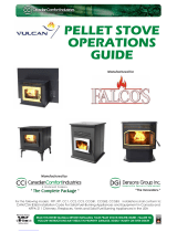
Fuel in the form of wood pellets , shelled corn or grain is stored in the hopper. An
auger delivers the pellets to the burn grate. The fuel rate, or heat output, is set by
adjusting the feed rate touch pad, (settings 1 to 4). A fan provides combustion air to
the burn grate. The amount of combustion air in the burn grate is adjustable and
automatically changes as the fuel rate changes. The higher the fuel rate, the larger
the amount of combustion air and visa versa. The fuel burns in the burn grate,
producing heat. Some heat radiates out the front of your stove. The majority of the
heat passes around the heat exchange tubes and air plenum around the firebox and
is then moved into the room by the room air fan. A small amount of heat must pass
out the exhaust of your stove, along with gases, into the atmosphere.
Your stove's heat output can be adjusted from setting 1-4, through the FEED RATE
touch pad, to vary your heat
output from Low to High.
The room air fan can be
manually adjusted through
the FAN SPEED to run
faster or slower to
correspond to the amount of
heat being produced. The room air fan is also on a
limit switch, controlled to run on high when the stove
reaches higher temperatures and then resume the
speed you had selected once it cools to a lower
temperature.
Your stove can run efficiently over extended periods of
time and at different heat output levels as long as the
fuel supply is uninterrupted and timely cleaning and
maintenance is preformed. An example of how
improper cleaning effects operations is; the
exhaust pressure switch will shut the pellet supply off
and your stove will shut off if the exhaust system be-
comes plugged.
The operations and maintenance of your Glow Boy Series of multi-fuel appliance are unique and
should not be considered to be like a wood, coal, gas, electric, propane or oil heater, stove or appliance.
FUEL CONSIDERATIONS
Your Glow Boy Series of Multi-fuel appliance is designed to burn the following:
1. Wood pellets that comply with the Pellet Fuel Industries standards.
2. A combination of up to 50/50 Wood Pellet and Shelled Corn
3. 100% Shelled Corn or Grain, using the Multi—Fuel Grate, and manual start only, No Igniter.
Window
Burn Pot
Burn Grate
Heat Tubes
Tube Scraper
Ash Pit
Hopper
Fan Motors
Auger
Exhaust
A
ir Intake
A
uger Motor
Base
Hopper Lid
as desiredas desired
Memory &
Fan Trim
Glow Boy Home & Shop Heater www.glowboystoves.com 6

7
A
A
UTOMATIC
UTOMATIC
S
S
AFETY
AFETY
F
F
EATURES
EATURES
L120 LOW LIMIT SWITCH
This limit switch is mounted on the exhaust blower housing and has 2 main functions:
Should the fire happen to go out, for any reason, this limit switch will shut the stove off when the exhaust
temperature drops below 120° F.
Upon starting the appliance, the AcuTron control board has a 15 minute “Lighting Mode”, if the stove
exhaust does not reach 120° F in that 15 minutes the stove will shut off. As soon as the stove
exhaust does reach 120° F, the limit switch opens and the AcuTron enters a 5 minute “Safety Delay”
mode.
F140 FAN LIMIT SWITCH
Your pellet appliance has a convection fan control limit switch. The room air fan's (F140) temperature limit
snap switch automatically operates the fan on high when your stove is producing heat faster than the fan is
carrying it into the room. This may occur when the heat control lever is set at [3 or 4] and the FAN SPEED is
set to a very low or off setting. After the fan runs at this automatic high setting a few minutes, it may cycle back
to its lower setting and may continue to cycle between [HIGH] and your selected setting. The circulation (room
air) fan cycling from high to low is a normal condition as well as a safety feature of your appliance.
To compensate for the fan cycling, adjust the FAN SPEED to a higher setting.
L250 HIGH LIMIT SWITCH
Your pellet appliance has a high temperature limit switch installed. If the temperature at the back of the firebox
reaches approximately 250° F., the switch will shut off the electricity going to the Vacuum Switch and to the
Auger Motor. The auger will automatically stop, and the appliance will shut down when the exhaust
temperature cools (120° F). If this happens call your dealer or Dansons Customer Service (1-866-456-9269).
IT IS IMPORTANT TO FIND THE REASON WHY THE UNIT OVERHEATED.
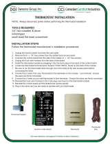
VACUUM SWITCH
This safety device (mounted on the back panel pillar) detects vacuum in the exhaust system, firebox, and air
intake. If the exhaust blower fails, the vent pipe becomes plugged, the viewing door is open, or if you are out
of pellets, this switch will sense that there is a lack of vacuum and will stop the auger from continuing to feed
pellets.
HOPPER LID SWITCH
This device is mounted inside the
hopper.and is connected to the
auger feed system.……
If the hopper lid is OPEN the switch
WILL STOP THE AUGER FEED
SYSTEM. This is to prevent fingers,
clothing or other objects from
coming in contact with the auger.
The auger is capable of causing
serious injury and this switch
MAY NOT be disconnected.
AcuTron Wiring Harness
Air Intake
Vacuum Switch
Low Limit L120
High Limit L250
Fan Limit F140
Combustion Fan
Exhaust
Left Hand Side View
/ Exhaust Fan Side
If the power does go out, the pellet appliance will stop running. When the power comes back
on, the stove will remember the function it was performing and return to that function.
Glow Boy Home & Shop Heater www.glowboystoves.com 7

8
S
S
PECIFICATIONS
PECIFICATIONS
HEATING SPECIFICATIONS
DIMENSIONS
ELECTRICAL SPECIFICATIONS
Electrical Rating = 115 Volts 60 HZ 2.0 Amps
Watts (operational) = 175 (approximately)
Watts (optional igniter) = 475 (approximately)
A voltage surge protector or ground fault outlet is required for this unit. The warranty on the circuit
board will be voided if surge protection is not installed before operating this unit.
If power outages or disturbances are a concern, you may wish to purchase a gas powered generator,
solar or battery back-up system. Ensure that it is a “Positive” sign wave and a minimum 1000 watts
continual.
EPA COMPLIANCE
This heater is exempt from EPA Phase II requirements, but has been tested for emissions using EPA test
methods by Warnock Hersey , US. Pellet appliances that are designed with the combustion air supply ex-
ceeding 35:1 (by ratio) are exempt from EPA regulations.
PRODUCT IS SUBJECT TO CHANGE WITHOUT NOTICE.
¹ Heating capacity will vary depending on floor plan layout of your home, degree of insulation, and
the outside temperature. Fuel size, quality, density and moisture level will also have an effect.
¹¹ Pellet size may affect the actual rate of fuel feed and burn times. Fuel feed rates may vary by as
much as 20%. Use PFI listed fuel for best results.
Approx. Heating capacity (sq. feet) * 800 – 2,000
Approx. Fuel burn rate per hour ** 1.5 – 5 lbs
Hopper Capacity - Home 120 120 lbs Approx. Burn time at lowest setting 90 hrs
Hopper Capacity – Home 300 300 lbs. Approx. Burn time at lowest setting 200 hrs
+
+
8 1/4”
8 3/4”
14 1/4”
3 3/4”
26”
24”
46 1/2”
8 3/4”
24”
31 1/2”
Glow Boy Shop 300 /
or Home 300
Glow Boy Shop 120 /
or Home 120
Common for
all models
Weight
272 lbs.
225 lbs.
Exhaust
Air Inlet
Glow Boy Shop 300 /
or Home 300
Glow Boy Shop 120 /
or Home 120
+
+
8 1/4”
8 3/4”
14 1/4”
3 3/4”
26”
Exhaust
2” Air Inlet
Glow Boy Home & Shop Heater www.glowboystoves.com 8

9
P
P
LANNING
LANNING
& I
& I
NSTALLATION
NSTALLATION
C
C
HECK
HECK
L
L
IST
IST
Unless you are knowledgeable and experienced in stove installation, we recommend your Glow Boy Appliance
receive a Pre-delivery Check and be installed by your local Specialty Retailer, NFI (National Fireplace Institute)
Pellet Specialist (USA) or WETT Certified Installer (CAN) .
COMPLETE THIS CHECK LIST PRIOR TO INSTALLING YOUR MULTI-FUEL APPLIANCE:
_____ Carefully read this "Owners Manual”. SAVE THIS MANUAL.
_____ Have your local Dealer demonstrate all the operational, cleaning and maintenance steps
necessary for your stove.
_____ Select a location. The design of your home and the stove placement will determine its value
as a source of heat. A pellet appliance depends primarily on air circulation to disperse its
heat. There are other practical considerations, which must be considered before a final
placement is decided on:
Existing Chimneys, Pellet Fuel Storage, Aesthetic Considerations, Roof Design (rafter
locations & roof pitch), Room Traffic, Clearances to Combustibles, and Existing Wiring.
_____ The installation of this appliance must conform to local codes and applicable state and
federal requirements. Becoming familiar with these requirements before installation is
essential.
_____ Sign and keep a copy of the Pre-delivery Check List supplied by your Authorized Dealer, OR
“Dansons Certified Installer”, found inside our appliance or available online.
______ Attach your proof of purchase to this manual and keep on hand for warranty.
COMPLETE THIS CHECK LIST WHILE INSTALLING YOUR MULT—FUEL APPLIANCE:
_____ Carefully read the ENTIRE installation section first. Twice is better.
_____ Read the Installing Freestanding, Insert or Built-In sections.
_____ Determine the location and measurement needed your chosen location.
_____ Be sure to pre-fit all items before you install, fasten or install the stove permanently.
Remember measure twice, cut once.
_____ Ensure ALL joints of “PL” vent and single wall stainless steel liner are tightly connected,
sealed with RTV Silicone or Hi-Temp foil tape, including to the exhaust connector, and
is correctly installed. (Follow vent manufacturer’s instructions.)
COMPLETE THIS CHECK LIST PRIOR TO LIGHTING YOUR FIRST FIRE:
_____ Obtain final inspection and approval by local building officials.
_____ Carefully clean all marks off the brass, nickel or pewter parts before the first fire is lit. Use a
soft cloth and a gentle type cleaner. Caution: Never use an abrasive cleaner on any part of your
stove.
_____ Polish the hopper to remove the oil type coating used in manufacturing.
_____ The high temp. stove paint used on your stove may take several hours of burning at a high fuel
setting to fully cure. During this time an odor, which is not harmful, may be evident. The area
around the stove should be well ventilated.
_____ Review and follow the Lighting and Controls Instructions.
_____ Ensure that appliance is connected to a surge protection unit.
_____ Fill the hopper with quality pellets, Close the Hopper Lid, Using the CCI “AcuTron”,
(figure 5), PUSH the FEED RATE Touch Pad and this will start the auger and the combustion fan.
Glow Boy Home & Shop Heater www.glowboystoves.com 9

10
P
P
LANNING
LANNING
—
—
E
E
XHAUST
XHAUST
S
S
YSTEMS
YSTEMS
PELLET VENT MUST MAINTAIN A MINIMUM 3” CLEARANCE TO ANY COMBUSTIBLE
(INSTALL VENT AT CLEARANCES SPECIFIED BY THE VENT MANUFACTURER).
DO NOT CONNECT THE PELLET VENT TO A VENT SERVING ANY OTHER APPLIANCE OR
STOVE.
DO NOT INSTALL A FLUE DAMPER IN THE EXHAUST VENTING SYSTEM OF THIS UNIT.
PELLET VENT TYPE:
1. Must be an approved 3” or 4” Diameter Type ”PL” vent, vented to the outside (fig. 7) or connect
the vent to a factory built type “A” chimney using an adaptor.
2. Exception: A single wall “All Fuel” Stainless Steel chimney liner may be used inside a fireplace
or fireplace installations (fig. 8) .
3. Some venting manufactures do make “PL” vent for use with wood pellet fuel only and another
type of “PL” vent for corn or bio mass fuels. If in doubt, plan for the future and use the corn or
multi-fuel
VENT SAFETY PRECAUTIONS:
A “Clean Out Tee” (4) must be installed at the bottom of all vertical runs. These “Tee’s” are to assist in
periodically cleaning the vent. Single or Double clean out tees may be used. The exhaust system must
be installed so the entire system can be cleaned without disassembly.
Termination must exhaust above the fresh air inlet
elevation, and parallel or above the exhaust output
of the multi-fuel appliance.
It is highly recommended that at least 3 feet of vertical
pipe (5) be installed to create some natural draft. This is
to help prevent the possibility of smoke or odor during
the appliance shut down.
Horizontal sections must have a 1/4” rise every 12” of
travel after 3’ long.
Pellet vent connections must be sealed gas tight. Use
Hi-Temp RTV Silicone, good for over 600° F or Hi-temp
Metal foil tape, that meets UL181 standards,. DO NOT
use “Duct Tape”.
Seal each vent section by injecting a liberal amount of
sealant into the gap and/or wrap with foil tape.
It is strongly recommended that the exhaust system
be terminated on the prevailing wind side of the home.
Appliance may not be placed in, or vented through
a gas fireplace.
1
2
3
4
5
6
7
8
9
Glow Boy Home & Shop Heater www.glowboystoves.com 10

11
P
P
LANNING
LANNING
—
—
E
E
XHAUST
XHAUST
S
S
YSTEMS
YSTEMS
…
…
CONTINUED
CONTINUED
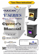
DETERMINE VENTING SIZE AND DISTANCE:
It is recommended that the vent system be installed with a minimum of three (3’) of vertical
rise above the appliance exhaust port.
Equivalent Vent Length (EVL) is the method of determining vent sizes and lengths, that takes into account the
effect of different component parts on air flow.
STEP 1 To help you determine the correct size and/or run, simply fill in the chart below.
Pellet Venting
Component
# of Elbows
OR feet of Pipe
Multiply by Equivalent
Feet
Component
Equivalent
90 Degree or Tee X 5
45 Degree X 3
Horizontal Pipe X 1
Vertical Pipe X .5
Total Equivalent
Step 2
Ensure the Total Equivalent is or is
less than 30.
Step 3 Use the Sizing Chart to determine
the proper venting size according to
the Total Equivalent and the
Altitude above sea level.
NOTE: In some cases it may be necessary
to contact Dansons Customer
Service personal to determine
acceptable venting
configurations
and altitude adjustments
1-877-303-3134.
The diagram to the right will help to
give you a visual reference.
0 1 2 3 4 5 6 7 8 9 10
10
20
30
Altitude in Thousands of Feet
E
q
u
i
v
a
l
e
n
t
P
i
p
e
L
e
n
g
t
h
i
n
F
e
e
t
3 or 4 Inch Diameter Pipe
4 Inch Diameter Only
Use Diameter “PL” Vent
If venting outside of
shaded area.
4”
0’
0’
5’
5’
10’
10’
15’
20’
25’
30’
33’
Vent must have a support
bracket every 5’ when on
the exterior wall.
Vent height and run
exceed the distance
shown in the un-shaded
region of chart.
must
not
To achieve optimum
performance, keep vent runs
as short as possible.
Especially on horizontal
installations.
Use or Diameter
“PL” Vent, if venting in
shaded area.
3” 4”
Maximum venting height is 33’.
Maximum horizontal offset is 10’.
Use the Equivalent Vent Length
Chart to determine proper
combination of component parts.
Glow Boy Home & Shop Heater www.glowboystoves.com 11

12
P
P
LANNING
LANNING
—
—
E
E
XHAUST
XHAUST
S
S
YSTEMS
YSTEMS
…
…
CONTINUED
CONTINUED
PELLET VENT TERMINATION: (Figures 7 & 8)
Termination must be a minimum of 12” above the chase cap (B) (note: the chim-
ney must meet local codes for height above the roof or
other obstructions)
Must have an approved cap (G) (to prevent water from en-
tering) or a 45* elbow downturn (F)
If the termination is located on a windy side of house, an
approved house shield is recommended to prevent soot
from accumulating on the side of the house.
Must not be located where snow or other materials such as
leafs, snow or grass, could block it.
Must have a “Metal Seal Plate” or “Wall Thimble” at point
(A) Figure 7 Figure 8
VENT TERMINATION CLEARANCES:
NOTE: Horizontal terminations must protrude 12” from the wall, vertical terminations 24”
A Minimum 4’ clearance below or beside any door or window
which opens.
B Minimum 1’ clearance above any door or window that opens.
C Minimum 3’ clearance from any adjacent building.
D Minimum 7’ clearance above any grade when adjacent to public walkways.
E Minimum 2’ clearance above any grass, plants, or other combustible material.
Minimum 1’ clearance above grade.
F Minimum 3’ clearance above any forced air intake of any other appliance within 6’.
G Minimum 2’ clearance below eves or overhang.
H Minimum 1’ clearance horizontally from combustible wall
.
I Minimum 1’ clearance to inside corner
X Must be a minimum of 36” above the roof and 24” above the highest point of the roof within 10’.
NOTE: The following are not found on the above diagram.
•Minimum 3’ above a gas meter/regulator within 3’ horizontally of the vertical centre line of regulator.
•Minimum 6’ clearance to a gas service regulator vent outlet.
•Minimum 1’ clearance under veranda, porch, deck or balcony. Permitted only if structure is fully
open on a minimum of two sides beneath the floor.
A
B
A
B
3’
10’
2’
x
Inside Corner
Detail
I
E
Glow Boy Home & Shop Heater www.glowboystoves.com 12

13
P
P
LANNING
LANNING
—
—
O
O
UTSIDE
UTSIDE
A
A
IR
IR
Outside air is REQUIRED ON ALL MOBILE HOME INSTALLATIONS.
Outside air is strongly recommended for all other installations. Failure to install intake
air may result in improper combustion as well as the unit smoking during power failures.
Metal pipe, ONLY, either solid or flexible, must be used in all outside air installations.(B)
NOTE: Non-metallic material, such as PVC or ABS plastic,
MUST NOT BE USED for outside air installations.
A wind shield, (C), over the termination of the outside air pipe or a 90 degree elbow or
bend directed away from the prevailing winds MUST be used when an outside air pipe
is in-stalled through the side of a building. Keep the outside air pipe termination at least
1 foot away from the exhaust system termination.
When outside air is taken from an existing chimney, the exhaust system must not
terminate in the same chimney.
The outside air pipe on your stove is 2" OD. The outside air connecting pipe must be at
least 2" ID The outside air connecting pipe must be as short and free of elbows as
possible, and must fit over, (A), not inside, the outside air pipe on your stove.
For distances over 10’ long, 3” or 4” OD pipe is recommended, then reduce to 2”.
Through The Wall Kits Include:
3 FOOT PACKAGE – PART# 5150-1450 10 FOOT PACKAGE – PART# KS5150-1460
1 – 2” Galvanized Hood c/w screen 1 – 2” Galvanized Hood c/w screen
1 – 2” Aluminum Flex Duct – 1 – 2” Aluminum Flex Duct –
compressed 15” length, extends to 30” – 36” compressed 4’ length, extends to 120”
2 – 2” Worm Gear Clamps 2 – 2” Worm Gear Clamps
NOTE: Available from your local
Authorized Dealer or Dansons Inc.
1-877-303-3134
Figure 11
Glow Boy Home & Shop Heater www.glowboystoves.com 13

14
P
P
LANNING
LANNING
—
—
P
P
ROTECTION
ROTECTION
& C
& C
LEARANCES
LEARANCES
STOVE PLACEMENT:
FLOOR PROTECTION REQUIREMENTS:
MINIMUM CLEARANCES TO COMBUSTIBLES: Figure 10—15
NOTE: Although not required for safety reasons, it is strongly suggested that sufficient space be provided
(a minimum of 24”) on each side of the appliance and at the back of the appliance to enable servicing the unit
if necessary. If this space is unavailable, a provision must be made to enable sliding the appliance out.
CLEARANCES – “STRAIGHT INSTALLATION”:
Stove must be placed so that no combustibles are within, or can swing within (i.e. drapes doors),
36” of the heater.
Keep in mind the following placement concerns; venting obstructions, outside air, electrical
outlet, wall thermostat, heat distribution, traffic patterns and room use/size.
If the stove is placed in a location where the ceiling height is less than 7’, it must follow the
requirements in the section “Alcove Installation”.
Stove and floor protection must be installed on a level secure floor
NOTE: It is important for your appliance to be level. Leveling should occur below the floor
protection pad.
The stove must be installed on a continuous (grouted joints) non-combustible floor protector
such as ceramic tile, cement board, brick, 3/8” millboard or equivalent, or other approved or
listed material suited for floor protection.
THE MATERIAL(S) USED MUST HAVE, OR COMBINE TO HAVE, A MINIMUM INSULATIVE
RATING OF “R1”.
Must extend 6in (300mm) beyond the front of the stove as well as 6 in (300mm) beyond each
side of the fuel loading and ash removal opening(s)
Must extend under and 2” to each side of chimney tee (if used).
2” From Back Of Stove to Combustibles 3” From PL Vent to Combustibles
10” From Front Side of Stove to Combustibles
2” From Back Corner of Stove to Combustibles 6” Non Combustible Surface In Front Of Heater
16” From Top Of Stove to Combustibles 36” to drapes, doors, anything that can swing
Glow Boy Home & Shop Heater www.glowboystoves.com 14
6”
1”
10”
6”
2”
10”
12”
HROUGH HE ALLT T
W
6”
3”
10”
NTERIOR ERTICALI V
6” 6”
6”
6”
10”

15
16”
P
P
LANNING
LANNING
—
—
P
P
ROTECTION
ROTECTION
& C
& C
LEARANCES
LEARANCES
. . . C
. . . C
ON
ON
’
’
T
T
CLEARANCES – “CORNER INSTALLATION”:
Figure 12 Figure 13
Note: If interior vertical vent is used (figure 13), the clearance to the back wall is determined by the
upward-turned “Clean Out Tee”. It will vary in depth depending on the brand of PL vent used.
Before placing the stove, connect the “Tee” and measure off the 3” clearance.
ALCOVE INSTALLATION:
Minimum clearances to combustibles: (Figure 14 & 15)
2 inch from back of appliance 10 inches from the sides
16 inches from the top 30 inches deep
Figure 14 Figure 15
Glow Boy Home & Shop Heater www.glowboystoves.com 15
2”
12”
6
”
T
HROUGH
T
HE
W
ALL
45 C
ORNER
3
”
6”
10”
I
NTERIOR
V
ERTICAL
45 C
ORNER
10”
1
0
”
6”
6”
6”
6
”
6”
1”
10”
6”
2”
12”
A
LCOVE
-
T
HROUGH
T
HE
W
ALL
6”
6”
10”
10”

16
T
T
OOLS
OOLS
R
R
EQUIRED
EQUIRED
Power Tools
Shop Vacuum WITH Filter
Jigsaw or Reciprocating saw
Electric drill
Extension cord
4” or 5” diameter coring bit and drill
(if going through concrete)
Hand Tools
Tape Measure
Caulking Gun
Circle Maker
Allen (Key) wrench set
Stud Finder
Set of sockets or nut driver 1/4”, 5/16” and
7/16”
Assortment of Phillip, Robertson and slot
screwdrivers
Assortment of sheet and wood drill bits
Flashlight
Wire stripper and wire cutter
Hammer
Bubble Level
Utility knife
Adjustable pliers (6 to 8 inches)
Small hand broom and dustpan
Furniture and Floor Protection
Supplies
Caulking tube of RTV Hi-Heat Silicone
2” long Wood screws (10+)
Assortment of sheet and wood screws
“Stove Bright” Hi-Heat Stove Paint
Caulking tube of Clear Silicone
Hi–Heat Aluminum Foil Tape
Before starting your Glow Boy Multi-Fuel install, we recommended you have the following list of tools ready.
This is not an exhaustive list, but should go along way in making your installation easier.
Glow Boy Home & Shop Heater www.glowboystoves.com 16

17
I
I
NSTALLATION
NSTALLATION
—
—
F
F
REESTANDING
REESTANDING
THROUGH THE WALL, DIRECT VENT INSTALLATION. (not preferred) (Figure 18)
1. Select the location for your stove, design the exhaust
system and determine the brand and size of "PL"
vent to be used.
2. Position the floor pad.
3. Following the "PL" vent manufacturer's specifica-
tions, mark and cut a hole through the wall to accom-
modate the wall thimble, (F), and the outside air pipe,
(I), if outside air is to be used. Remember that the
outside air intake must be located no closer than 12”
from the vent exhaust. Try to avoid cutting wall studs,
and use extreme caution to avoid cutting into power
or water lines within the wall of your home.
4. Install the wall thimble, (F). Be sure to run a bead of
silicone around the outside edges of the wall thimble
to reduce drafts, both inside and outside. Insert the
proper size of "PL" vent, (E), through the wall thimble,
(F).
5. Place your stove on the floor pad, close to its final position. Leave room to connect the "PL" vent to
“Quick Connect” end collar. If not already factory installed, Install the gasket (B) and “Quick Connect”
exhaust end (C) to your stove to the “Quick Connect” mounting plate. Use the 4 x 7/16” nuts, supplied
and secure tightly.
6. Place a bead of RTV silicone around the end collar of the “Quick Connect” of your stove's exhaust, (C).
Firmly push the “PL” vent pipe adaptor (J) into the bead of RTV silicone.
Note: If 4" PL vent is required, use an 3” to 4” Pipe Adaptor Increaser, (J), on the stove exhaust pipe.
7. Connect the length of "PL" vent, (E), that is in the thimble, (F), onto the pipe adaptor (D). Fasten
together with at least three sheet metal screws (approx. 3/8” in length). Place a bead of RTV silicone
around the connection.
8. Place your stove in its final position on the pad. Place another bead of RTV silicone around the “PL”
vent (E) and the inside of the wall thimble, to stop cold air drafts.
9. On the outside of the building, place an exhaust cap (G) or a 45 degree "PL" type elbow, (G), onto the
end of the horizontal "PL" vent, (E). Optionally, place a rodent screen cap, (G), (may be required in
some locals), on the end of the elbow, (G). run a bead of RTV silicone around all connections and
around the “PL” vent pipe and the outside of the wall thimble.
Note: The end of the exhaust pipe must extend a minimum of 12” from the outside of the building.
Note: Most horizontal, through the wall installations may require a Clean-out Tee and minimum 3’
vertical rise of pipe, inside or outside the building. See Next Page.
Glow Boy Home & Shop Heater www.glowboystoves.com 17
6”
1”
10”
6”
2”
10”
12”
T
HROUGH
T
HE
W
ALL
6”
6”
10”

18
M
M
OBILE
OBILE
H
H
OME
OME
I
I
NSTALLATION
NSTALLATION
CAUTION: DO NOT INSTALL STOVE IN SLEEPING ROOM
THE STRUCTURAL INTEGRITY OF THE MANUFACTURED HOME FLOOR,
CEILING and ROOF MUST BE MAINTAINED!
Your Glow Boy appliance has been tested and listed for mobile home installation. It may be
installed in a mobile home as a "Free Standing Stove" or a "Hearth Stove", see detailed install and
clearance requirements in these sections as they imply there.
In addition to all previously detailed installation requirements, mobile home in-stallations
must meet the following requirements in accordance with the Manufactured Home and
Safety Standard (HUD) CFR 3280, Part 24:
Permanently bolt your stove to the floor, (A), figure 25.
Electrically ground your stove or the pedestal to the steel frame of the home. Use a number 8 gauge
copper wire, (B), figure 25, or equivalent.
The stove must have a permanent outside air source with a ¼ inch screen over the inlet.
Figure 26, (B, C & D)
For transportation all chimney/vent above the mobile home must be removed.
Chimney/PL Vent must be 3” or 4” PL Vent and must extend a minimum or 36” above the roofline
of the mobile home and must be installed using a UL / ULC listed ceiling fire stop (J), figure 26,
and rain cap (L), figure 26., when installing as a vertical run. See diagram below.
REFER TO THE VENTING DIAGRAMS IN THIS MANUAL FOR FURTHER EXHUAST CONFIGURATIONS.
INSTALL VENT AT CLEARANCES SPECIFIED BY THE VENT MANUFACTURER.
Figure 25 Figure 26
Note: When moving your mobile home, all exterior venting must be removed. Upon completion of relocation,
all venting must be reinstalled, gas tight, and securely fastened.
A
Floor Pad
B
Combustion Air Intake
C
Fresh Air Duct
D
Fresh Air Hood
E
Stove Exhaust
F
Pipe Adapter
G
Clean Out Tee
H
Tee Support Bracket
I
Pipe
J
Firestop Spacer / Ceiling Support
K
Roof Flashing / Storm Collar
L
Rain Cap
B
A
C
D
E
F
G
H
J
K
L
FRAME
HEARTH PAD
FLOOR
B
GROUND
WIR E
A BOLT(S)
Glow Boy Home & Shop Heater www.glowboystoves.com 18

19
Walkout Basement or Main Floor
Basement or Main Floor
1
Pipe Adapter
Clean Out Tee & Cap
Tee Support Bracket
Horizontal Rain Cap
2
3
4
5
6
7
8
90 Deg Elbow
36” Pipe Length
12” Pipe Length
12” Adjustable Pipe Length
Wall Thimble9
1 Pipe Adapter
Clean Out Tee & Cap
Tee Support Bracket
Horizontal Rain Cap
2
3
4
5
6
7
8
90 Deg Elbow
36” Pipe Length
12” Pipe Length
12” Adjustable Pipe Length
Wall Thimble
9
10
24” Pipe Length x 2
10
1
2
3
4
5
6
7
8
Ground Level
Floor / Ceiling
12”
12”
9
9
Tube of RTV Silicone
Roll of Foil Tape
3/8” Stainless Self-Tapping
Screws x 27
2” Wood Screws x 10
Options
Tube of RTV Silicone
Roll of Foil Tape
3/8” Stainless Self-Tapping
Screws x 21
2” Wood Screws x 10
1
2
3
4
5
6
7
8
9
These styles of installation are highly recommended, due to possible backpressure in the exhaust caused by
airflow around the outside of the structure, snow build-up, or power failure, etc.. These designs will improve
venting performance and provide natural draft to help evacuate smoke from the appliance in case of power
failure.
Follow the same basic steps in locating your appliance, attaching the exhaust system and outside air intake to
your stove as the previous examples.
1
2
3
4
5
6
7
8
Main Floor - Vertical
1 Pipe Adapter
Clean Out Tee & Cap
3 x 60” (15’) Pipe Length
Tee Support Bracket
Ceiling Support / Firestop Spacer
Roof Flashing
Storm Collar
Vertical Rain Cap
2
3
4
5
6
7
8
Tube of RTV Silicone
Roll of Foil Tape
3/8” Stainless Self-Tapping
Screws x 27
2” Wood Screws x 10
8”
16”
Optional
Metal Plate
1
2
3
4
5
6
7
8
9
24”
Hearth Stove - Existing Reline
1 Pipe Adapter
Single Wall Stainless Steel
Clean Out Tee & Cap
Storm Collar
Vertical Rain Cap
2
3
4
5
6
7
8
Hi Heat Insulation
“All Fuel” Stainless Steel
Flex Liner
Roof Flashing
Liner Support
Dripless Connection
9
Tube of RTV Silicone
Roll of Foil Tape
3/8” Stainless Self-Tapping
Screws x 27
6”
PL Vent Length10
10
Outside Air may be obtained from a suitable duct passing through the
ash clean-out opening.
Ensure the chimney top is properly sealed to prevent intrusion of
weather and down drafts with suitable flashings, collars, and sealants.
F
F
REESTANDING
REESTANDING
I
I
NSTALLATION
NSTALLATION
. . . C
. . . C
ON
ON
’
’
T
T
Glow Boy Home & Shop Heater www.glowboystoves.com 19

20
F
F
REESTANDING
REESTANDING
I
I
NSTALLATION
NSTALLATION
. . . C
. . . C
ON
ON
’
’
T
T
2
Main Floor - Tie-In Claytile Flue
1
“PL” Pipe Adapter
Single Wall Stainless Steel
Clean Out Tee & Cap
Storm Collar
Vertical Rain Cap
2
3
4
5
6
7
8
Hi Heat Insulation
“All Fuel” Stainless Steel
Flex Liner or “PL” Venting
Roof Flashing
Liner Support
Dripless Connection
9
Tube of RTV Silicone
Roll of Foil Tape
3/8” Stainless Self-Tapping
Screws x 27
7
6
24”
8
“PL” Clean Out Tee & Cap
“PL” Length of Pipe
“PL” 90D Elbow
“PL” Wall Thimble
10
11
12
1
2
3
4
5
Cleanout
Door
9
10
11
Main Floor - Class A Tie-In
1 Pipe Adapter
Clean Out Tee & Cap
3 x 60” (15’) Pipe Length
Tee Support Bracket
Ceiling Support / Firestop Spacer
Roof Flashing
Storm Collar
Vertical Rain Cap
2
3
4
5
6
7
8
Tube of RTV Silicone
Roll of Foil Tape
3/8” Stainless Self-Tapping
Screws x 27
Outside Air
Intake
“PL” Adjustable length
“PL” to Class A Adaptor
Class A Fittings
Lengths of Pipe
9
10
11
1
3
4
5
6
7
8
9
10
11
Glow Boy Home & Shop Heater www.glowboystoves.com 20
/