Page is loading ...

Features
Remote LCD annunciator for use with Simplex
®
model:
4100ES and 4100U fire alarm control panels
Legacy products 4100, 4120, and 4020 fire alarm control
panels, and 4100/4120 Universal Transponders
Information display features:
Maintained display of first alarm is available with
4100ES and with 4100U at software revision 11.11 or
higher
Wide viewing angle, super-twist LCD technology with
green LED backlighting
Two lines of 40 characters each
LED status indicators
During battery backup, backlighting is disabled until
there is switch activity
Controls include:
Switches for system acknowledge, alarm silence, and
system reset
Four programmable control switches
Lamp/LCD test
Wiring information:
RUI (Remote Unit Interface) communications require a
single twisted wire pair (see p. 3 for more information)
Separate wiring is required for 24 VDC control panel
power
Flush mount on standard electrical boxes
Options:
2975-9206, Surface mount box
4603-9111, Brushed stainless steel trim
UL Listed to Standard 864
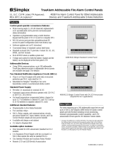
Description
Remote Control and Annunciation is provided using
an 80 character, back-lit, alphanumeric display.
Information is presented in clear, descriptive English
language and includes: Point Status (alarm, trouble, etc.);
Alarm Type (smoke detector, manual station, etc.);
Number of System Alarms, Supervisory Conditions,
and Trouble Conditions; and a Custom Location Label.
Wiring. A single twisted wire pair provides serial RUI
communications that also supports other Simplex serial
annunciators on the same wire pair.
Multiple Indications. Alarm, Supervisory, and Trouble
conditions are also indicated by dedicated LEDs and a
tone-alert audible sounder. Each condition has a dedicated
acknowledge push-button switch that silences the
tone-alert but leaves the LED on until all conditions in
that category are restored to normal. Switch operation is
either globally or individually acknowledgeable,
determined by the control panel operation.
4603-9101 LCD Annunciator
Description (Continued)
Repeated operation of the appropriate acknowledge
switch will scroll the LCD display showing activity in the
sequence of occurrence. The tone-alert also pulses to
indicate the operation of any of the push-button switches.
Consult local code requirements for guidance in
determining applications and location of the 4603-9101
LCD annunciator.
Operation
System Controls. Notification appliances can be
deactivated by pressing the “ALARM SILENCE” switch.
(Exact operation is determined by the host control panel
such as visible appliances remaining on until system is
reset.) Pressing the “SYSTEM RESET” switch restores
the system to normal operation. When system activity is
normal, the LCD displays the time, date, and “SYSTEM
IS NORMAL.”
Control Switches. Four programmable “CONTROL”
switches and associated LEDs are included. Typical
applications include manual evacuation, door holder
release bypass, and elevator capture bypass.
Keyswitch Enable. All switches on the annunciator are
controlled by the “ENABLE” keyswitch with a key that is
removable only in the disabled position. A brief
lamp/LCD test is performed whenever the keyswitch is
changed from enabled to disabled.
Battery Backup Operation. During battery backup,
the LED backlighting is disabled to conserve battery
power. When an annunciator switch is activated, the
backlighting is automatically enabled. After
approximately 30 seconds of inactivity, the backlighting
will again be disabled.
* This product has been approved by the California State Fire Marshal (CSFM) pursuant to
Section 13144.1 of the California Health and Safety Code. See CSFM Listing
7120-0026:0179 for allowable values and/or conditions concerning material presented in
this document. It is subject to re-examination, revision, and possible cancellation.
Accepted for use – City of New York Department of Buildings – MEA35-93E. Additional
listings may be applicable; contact your local Simplex product supplier for the latest
status. Listings and approvals under Simplex Time Recorder Co. are the property of Tyco
Fire Protection Products.
System Accessories, LCD Annunciators
UL, ULC Listed; FM, CSFM, 4603-9101 LCD Annunciator for
and MEA (NYC) Approved* 4100ES and 4100U Fire Alarm Control Panels
S4603-0001-13 1/2016

FIRE
ALARM
ALARM
SILENCED
PRIORITY 2
ALARM
SYSTEM
SUPERVISORY
SYSTEM
TROUBLE
POWER
ON
SYSTEM
RESET
DISPLAY
TIME
ALARM
ACK
ALARM
ACK
SUPV
ACK
TBL
ACK
ALARM
SILENCE
2 X 40 LCD READOUT, green LED
backlighted during normal conditions
and abnormal operating conditions
SUPV ACK acknowledges System
Supervisory conditions and silences the
panel and all annunciator tone-alerts
TROUBLE ACK acknowledges
System Troubles and silences the
panel and all annunciator tone-alerts
CONTROL ENABLE
KEYSWITCH
controls all switch functions;
key is removable only in
disabled position
ALARM SILENCE causes audible and
visible notification appliances to be
silenced (default operation, may be
modified through panel programming for
compliance with local requirements)
SYSTEM RESET restores
control panel to normal
when all alarmed inputs
are returned to normal
ALARM ACK/FIRE ALARM acknowledges
a Fire Alarm condition and silences the
panel and all annunciator tone-alerts
FOUR PROGRAMMABLE (Yellow) LEDs,
each with pushbutton switch and custom
labeling pocket
SIX STATUS INDICATOR LEDs provide system status
indications in addition to LCD information; LEDs flash to
indicate the condition and then when acknowledged,
remain on steady until reset; Fire Alarm and Priority 2
Alarm are red; System Supervisory, System Trouble,
and Alarm Silenced are yellow; Power On is green
DISPLAY TIME
displays time of last
occurrence of event
list being displayed;
or displays current
time when viewing
system status
information
ALARM ACK/PRIORITY 2 acknowledges
a Priority 2 Alarm condition and silences
the panel and all annunciator tone-alerts
2 S4603-0001-13 1/2016
Model Description
4603-9101 Remote LCD Annunciator with beige trim
Refer to specifications on page 3 for
additional details
4603-9101CF
Remote LCD Annunciator with beige trim, with French
keypad for Canada
4603-9111 Brushed stainless steel trim option
2975-9206 Matching surface mount box; ivory finish
2081-9044
Overvoltage protector; required where annunciator communications and power wiring exits and enters a
building; refer to data sheet S2081-0016 for details
4603-9101 Operator Information
Product Selection

3 S4603-0001-13 1/2016
General Operating Specifications
Voltage 18 to 32 VDC, system supplied
Normal Operating Current 110 mA (with LED backlighting on)
Battery Standby Current
65 mA (during battery backup, LED backlighting is turned off after 30 seconds without
switch activity)
Alarm Current 140 mA maximum (LED backlighting is on and tone-alert is sounding)
Operating Temperature Range 32° to 120° F (0° to 49° C)
Operating Humidity Range Up to 93% RH, non-condensing at 100° F (38° C)
Communications
4100ES/4100U Capacity,
Per RUI Output
Type
RUI (Remote Unit Interface) external annunciator communications line SLC (signaling
line circuit)
Capacity
Up to 31 remote annunciators/MINIPLEX transponders per channel including the
4603-9101 LCD Annunciator, the 4602-9101 Status Command Unit (SCU), and
4602-9102 Remote Command Unit (RCU); refer to data sheet S4100-0031 for
additional 4100ES information
Wiring Requirements
RUI Data
Standard Wiring Type Unshielded twisted pair (UTP), 18 AWG (0.82 mm
2
) for most applications, see below
Wiring Characteristics
0.58 µF (580 nF) maximum capacitance between conductors; 35 maximum total
line resistance
Wiring Applications
Requiring Shielded,
Twisted Pair (STP)
1. Wiring that leaves the building. Also requires Isolated Loop Circuit Protectors on
each end, refer to data sheet S2081-0007 for 2081-9027 (200 mA), or
S2081-0008 for 2081-9028 (5 A)
2. Wiring run in 500 ft (152 m) or more of conduit.
3. Wiring closely bundled with standard IDNet communications or TrueAlert
addressable communications (not required when run with IDNet+
communications).
Class B “T-Tap” wiring
distance
Up to 10,000 ft (3048 m) total wiring; up to 2500 ft (762 m) to farthest device
Class X wiring distance Up to 2500 ft (762 m)
Power Wiring 18 to 12 AWG (0.82 mm
2
to 3.31 mm
2
) wires for 24 VDC system power
Earth Wiring
A dedicated earth ground connection to the electrical box is required for proper ESD
and EMI protection; wire in accordance with NFPA 70 (National Electrical Code)
Article 250
Mounting Information
NOTE: General Conduit Entrance
Requirement
Conduit entrance must be located a minimum of 2 ¾” (70 mm) from the front of the
box to clear assembly
Trim Dimensions 4 ½” H x 11
13
⁄
16
” W (114 mm x 300 mm)
Standard Trim Finish Steel, painted beige
4603-9111, Optional Trim
Brushed stainless steel (ordered separately); supplied with both slotted and tamper
resistant screws
Boxes for Flush Mounting
(supplied by others)
6-Gang, 3 ½” (89 mm) deep: RACO 965, 6-gang masonry box; RACO 590, gangable
switch box, 6 required; or equal
2975-9206, Surface Mount Box Option (ordered separately)
Dimensions 11
31
⁄
32
” W x 4 ⅝” H x 2 ¾” D (304 mm x 117 mm x 70 mm)
Finish Painted steel, ivory finish
4603-9101 LCD Annunciator Specifications
For additional information, refer to Installation Instructions 579-979.

TYCO, SIMPLEX, and the product names listed in this material are marks and/or registered marks. Unauthorized use is strictly prohibited. National Electrical Code and NFPA are
registered trademarks of the National Fire Protection Association (NFPA).
Flush Mount Masonry Box:
Use RACO # 965, 3-1/2" (89 mm) deep
or equal (supplied separately)
Flush Mount Ganged Boxes:
Requires 6-gang box, 3-1/2" (89 mm) min.
depth, use (6) RACO # 590 or equal
(supplied separately)
FIRE
ALARM
ALARM
SILE NCED
PRIORIT Y 2
ALARM
SYSTEM
SUPERVISO RY
SYSTEM
TROUBLE
POWER
ON
SYSTEM
RESET
DISPLAY
TIME
ALARM
ACK
ALARM
ACK
SUPV
ACK
TBL
ACK
ALARM
SILENCE
Surface Mount Box:
Simplex model 2975-9206
2-3/4” deep (70 mm)
(ordered separately)
Trim plate
LCD Annunciator Assembly
Terminal block
access at rear of
assembly, this side
Note: Review box choice with assembly layout before selecting conduit
entrance location to allow easy access to terminals
Wiring Notes:
1. Communications require a single 18 AWG twisted pair.
2. Power requires two, 18 to 12 AWG wires for 24 VDC system power,
plus Earth Ground to each electrical box.
3. Refer to Installation Instructions 579-979 for additional wiring
specifications.
Fire Alarm Control Panel
(4100ES shown)
4603-9101 LCD Annunciators
FIRE
ALARM
ALARM
SILENCED
PRIORIT Y 2
ALARM
SYSTEM
SUPERVISORY
SYSTEM
TROUBLE
POWER
ON
ALARM
ACK
SUPV
ACK
TBL
ACK
ALARM
ACK
ALARM
SILENCE
SYSTEM
RESET
DISPLAY
TIME
FIRE
ALARM
ALARM
SILENCED
PRIORITY 2
ALARM
SYSTEM
SUPERVISORY
SYSTEM
TROUBLE
POWER
ON
ALARM
ACK
SUPV
ACK
TBL
ACK
ALARM
ACK
ALARM
SILENCE
SYSTEM
RESET
DISPLAY
TIME
Tyco Fire Protection Products • Westminster, MA • 01441-0001 • USA S4603-0001-13 1/2016
www.simplexgrinnell.com
© 2012 Tyco Fire Protection Products. All rights reserved. All specifications and other information shown were current as of document revision date and are subject to change without notice.
Wiring Reference
Mounting Information
/