Page is loading ...

INSTRUCTION MANUAL
CS705 Snowfall Adapter
Revision: 11/15
Copyright © 1997- 2015
Campbell Scientific, Inc.


Limited Warranty
“Products manufactured by CSI are warranted by CSI to be free from defects in
materials and workmanship under normal use and service for twelve months
from the date of shipment unless otherwise specified in the corresponding
product manual. (Product manuals are available for review online at
www.campbellsci.com.) Products not manufactured by CSI, but that are resold
by CSI, are warranted only to the limits extended by the original manufacturer.
Batteries, fine-wire thermocouples, desiccant, and other consumables have no
warranty. CSI’s obligation under this warranty is limited to repairing or
replacing (at CSI’s option) defective Products, which shall be the sole and
exclusive remedy under this warranty. The Customer assumes all costs of
removing, reinstalling, and shipping defective Products to CSI. CSI will return
such Products by surface carrier prepaid within the continental United States of
America. To all other locations, CSI will return such Products best way CIP
(port of entry) per Incoterms ® 2010. This warranty shall not apply to any
Products which have been subjected to modification, misuse, neglect, improper
service, accidents of nature, or shipping damage. This warranty is in lieu of all
other warranties, expressed or implied. The warranty for installation services
performed by CSI such as programming to customer specifications, electrical
connections to Products manufactured by CSI, and Product specific training, is
part of CSI's product warranty. CSI EXPRESSLY DISCLAIMS AND
EXCLUDES ANY IMPLIED WARRANTIES OF MERCHANTABILITY
OR FITNESS FOR A PARTICULAR PURPOSE. CSI hereby disclaims,
to the fullest extent allowed by applicable law, any and all warranties and
conditions with respect to the Products, whether express, implied or
statutory, other than those expressly provided herein.”

Assistance
Products may not be returned without prior authorization. The following
contact information is for US and international customers residing in countries
served by Campbell Scientific, Inc. directly. Affiliate companies handle
repairs for customers within their territories. Please visit
www.campbellsci.com to determine which Campbell Scientific company serves
your country.
To obtain a Returned Materials Authorization (RMA), contact CAMPBELL
SCIENTIFIC, INC., phone (435) 227-9000. After an application engineer
determines the nature of the problem, an RMA number will be issued. Please
write this number clearly on the outside of the shipping container. Campbell
Scientific’s shipping address is:
CAMPBELL SCIENTIFIC, INC.
RMA#_____
815 West 1800 North
Logan, Utah 84321-1784
For all returns, the customer must fill out a “Statement of Product Cleanliness
and Decontamination” form and comply with the requirements specified in it.
The form is available from our web site at www.campbellsci.com/repair. A
completed form must be either emailed to repair@campbellsci.com or faxed to
(435) 227-9106. Campbell Scientific is unable to process any returns until we
receive this form. If the form is not received within three days of product
receipt or is incomplete, the product will be returned to the customer at the
customer’s expense. Campbell Scientific reserves the right to refuse service on
products that were exposed to contaminants that may cause health or safety
concerns for our employees.

Safety
DANGER — MANY HAZARDS ARE ASSOCIATED WITH INSTALLING, USING, MAINTAINING, AND WORKING ON OR AROUND
TRIPODS, TOWERS, AND ANY ATTACHMENTS TO TRIPODS AND TOWERS SUCH AS SENSORS, CROSSARMS, ENCLOSURES,
ANTENNAS, ETC. FAILURE TO PROPERLY AND COMPLETELY ASSEMBLE, INSTALL, OPERATE, USE, AND MAINTAIN TRIPODS,
TOWERS, AND ATTACHMENTS, AND FAILURE TO HEED WARNINGS, INCREASES THE RISK OF DEATH, ACCIDENT, SERIOUS
INJURY, PROPERTY DAMAGE, AND PRODUCT FAILURE. TAKE ALL REASONABLE PRECAUTIONS TO AVOID THESE HAZARDS.
CHECK WITH YOUR ORGANIZATION'S SAFETY COORDINATOR (OR POLICY) FOR PROCEDURES AND REQUIRED PROTECTIVE
EQUIPMENT PRIOR TO PERFORMING ANY WORK.
Use tripods, towers, and attachments to tripods and towers only for purposes for which they are designed. Do not exceed design
limits. Be familiar and comply with all instructions provided in product manuals. Manuals are available at www.campbellsci.com or
by telephoning (435) 227-9000 (USA). You are responsible for conformance with governing codes and regulations, including safety
regulations, and the integrity and location of structures or land to which towers, tripods, and any attachments are attached. Installation
sites should be evaluated and approved by a qualified engineer. If questions or concerns arise regarding installation, use, or
maintenance of tripods, towers, attachments, or electrical connections, consult with a licensed and qualified engineer or electrician.
General
• Prior to performing site or installation work, obtain required approvals and permits. Comply
with all governing structure-height regulations, such as those of the FAA in the USA.
• Use only qualified personnel for installation, use, and maintenance of tripods and towers, and
any attachments to tripods and towers. The use of licensed and qualified contractors is highly
recommended.
• Read all applicable instructions carefully and understand procedures thoroughly before
beginning work.
• Wear a hardhat and eye protection, and take other appropriate safety precautions while
working on or around tripods and towers.
• Do not climb tripods or towers at any time, and prohibit climbing by other persons. Take
reasonable precautions to secure tripod and tower sites from trespassers.
• Use only manufacturer recommended parts, materials, and tools.
Utility and Electrical
• You can be killed or sustain serious bodily injury if the tripod, tower, or attachments you are
installing, constructing, using, or maintaining, or a tool, stake, or anchor, come in contact with
overhead or underground utility lines.
• Maintain a distance of at least one-and-one-half times structure height, 20 feet, or the distance
required by applicable law, whichever is greater, between overhead utility lines and the
structure (tripod, tower, attachments, or tools).
• Prior to performing site or installation work, inform all utility companies and have all
underground utilities marked.
• Comply with all electrical codes. Electrical equipment and related grounding devices should
be installed by a licensed and qualified electrician.
Elevated Work and Weather
• Exercise extreme caution when performing elevated work.
• Use appropriate equipment and safety practices.
• During installation and maintenance, keep tower and tripod sites clear of un-trained or non-
essential personnel. Take precautions to prevent elevated tools and objects from dropping.
• Do not perform any work in inclement weather, including wind, rain, snow, lightning, etc.
Maintenance
• Periodically (at least yearly) check for wear and damage, including corrosion, stress cracks,
frayed cables, loose cable clamps, cable tightness, etc. and take necessary corrective actions.
• Periodically (at least yearly) check electrical ground connections.
WHILE EVERY ATTEMPT IS MADE TO EMBODY THE HIGHEST DEGREE OF SAFETY IN ALL CAMPBELL SCIENTIFIC PRODUCTS,
THE CUSTOMER ASSUMES ALL RISK FROM ANY INJURY RESULTING FROM IMPROPER INSTALLATION, USE, OR
MAINTENANCE OF TRIPODS, TOWERS, OR ATTACHMENTS TO TRIPODS AND TOWERS SUCH AS SENSORS, CROSSARMS,
ENCLOSURES, ANTENNAS, ETC.


i
Table of Contents
PDF viewers: These page numbers refer to the printed version of this document. Use the
PDF reader bookmarks tab for links to specific sections.
1. Introduction ................................................................. 1
2. Precautions ................................................................. 1
3. Initial Inspection ......................................................... 1
3.1 Ships With ............................................................................................ 2
4. Overview ...................................................................... 2
4.1 Antifreeze ............................................................................................. 3
4.1.1 Standard Car or RV Antifreeze is NOT Recommended ............... 3
4.2 Tipping Bucket Compatibility .............................................................. 3
5. Specifications ............................................................. 3
6. Installation ................................................................... 4
6.1 Siting .................................................................................................... 4
6.2 Mounting Pole ...................................................................................... 4
6.3 CM270 Installation .............................................................................. 7
6.4 CS705-to-Tipping Bucket Installation Procedure .............................. 11
6.5 Datalogger Programming ................................................................... 13
7. Maintenance .............................................................. 13
8. References ................................................................ 14
Appendix
A.
MSDS for Campbell Scientific CS705
Antifreeze .............................................................. A-1
Figures
6-1. Proper gage siting ................................................................................ 4
6-2. CM310 56-inch pole embedded in a concrete foundation .................... 5
6-3. Pedestal kit options .............................................................................. 6
6-4. Exploded view of the CM270 Mounting Bracket Kit .......................... 8
6-5. Two views of an assembled CM270 .................................................... 8
6-6. Mounting CM270 to the rain gage ....................................................... 9
6-7. CM270 pipe mounting (exploded view) ............................................ 10
6-8. CS705 mounted to pole using the CM270 Mounting Kit ................... 11
6-9. CS705 exploded view ........................................................................ 12
7-1. Mix ratio versus precipitation received .............................................. 13


1
CS705 Snowfall Adapter
1. Introduction
The CS705 Snowfall Adapter converts a TE525WS Texas Electronics Rain
Gage to a rain and snow gage. It consists of an antifreeze reservoir, overflow
tube, and catch tube. Snow captured in the catch tube dissolves into the
antifreeze raising the overall level. The mixture flows through the overflow
tube into the tipping bucket where it is measured. A slot in the top of the
overflow tube prevents the tube from developing a siphon.
Before installing the CS705, please study
• Section 2, Precautions
(p. 1)
• Section 3, Initial Inspection
(p. 1)
2. Precautions
• The CS705 possesses inherent delays and is not suitable for real-time
precipitation measurements (see Section 4, Overview
(p. 2)).
• Since regular maintenance is required, choose a site that is easily
accessible throughout the winter.
• Wear safety glasses and rubber or neoprene gloves while handling and
pouring antifreeze.
• Campbell Scientific strongly recommends using antifreeze consisting of a
1:1 mixture of propylene glycol and ethanol (PGE). Appendix A, MSDS
for Campbell Scientific CS705 Antifreeze
(p. A-1), provides MSDS
information for the PGE antifreeze offered by Campbell Scientific.
• Avoid using the antifreeze commonly used in cars or RVs. This
antifreeze, which consists of propylene glycol or ethylene glycol, increases
the likelihood of ice bridging (see Section 4.1, Antifreeze
(p. 3)).
• The antifreeze/snowfall mixture needs to be captured from the tipping
bucket gage and properly disposed of in accordance with local, state, and
federal regulations.
• The CS705 should be removed and cleaned in the summer, and reinstalled
before the winter season.
3. Initial Inspection
• Upon receipt of the CS705, inspect the packaging and contents for
damage. File damage claims with the shipping company.
• Immediately check package contents against the shipping documentation
(see Section 3.1, Ships With
(p. 2)). Contact Campbell Scientific about any
discrepancies.

CS705 Snowfall Adapter
2
3.1 Ships With
The CS705 is shipped with the CM270, CS705 Mounting Kit (pn 20621).
Refer to FIGURE 6-8 for information on positioning the various mounting
hardware.
The CM270 mounting kit includes the following:
• (1) Band clamp (pn 20605)
• (1) Band clamp (pn 20606)
• (1) Storage mount (pn 20636)
• (3) Screws (pn 9580, 1/4-20)
• (2) Flat washers (pn 4365)
• (2) Lock washers (pn 4366)
• (2) Carriage bolts (pn 31922)
• (2) Wingnuts (pn 27552)
• (1) Mast clamp (pn 27550)
• (3) Grommets (pn 30838)
• (1) Bottom plate (pn 31917)
• (1) V-shaped plate (pn 31413)
• (1) S-shaped plate (pn 31414)
• (2) Springs (pn 20628)
• (1) Spacer (pn 32009)
• (3) Screws (pn 30978)
4. Overview
The CS705 is manufactured by Campbell Scientific and is based on the paper
“Measuring Winter Precipitation with an Antifreeze-Based Tipping Bucket
System” presented at the 1996 Western Snow Conference (McCaughey and
Farnes, 1996). The design possesses inherent delays and is not suitable for real
time precipitation measurements. Three design factors contribute to
measurement delays:
• air / antifreeze mixture temperature
• surface tension in the overflow tube
• precipitation form
All precipitation falling into the catch tube eventually flows through the overflow
tube and is measured by the tipping bucket gage. A delay of minutes is expected
for liquid precipitation so long as a minimum volume of water (≈0.03 inches) is
reached. A delay of several hours (up to tens) is expected for snow. Lightest
density snow at very cold temperatures has the longest delay.
The CS705 converts the TE525WS Texas Electronic Rain Gage, into a year-
round precipitation gage. The CS705 is intended for use only during winter.
Like any sensor, optimum performance is obtained by regular site visits. Any
antifreeze-based precipitation gage orifice is susceptible to capping or snow
bridging.
The CS705 is coated with a smooth black coating to minimize
surface adhesion and maximize solar loading, but snow bridging
may still not occur.
NOTE

CS705 Snowfall Adapter
3
4.1 Antifreeze
Campbell Scientific recommends a 1:1 mixture of propylene glycol and ethanol
(PGE). PGE is available from Campbell Scientific in a package of four, one-
gallon containers. Antifreeze can only be shipped in multiples of four gallons
via UPS Ground and cannot be shipped outside of the continental United
States.
4.1.1 Standard Car or RV Antifreeze is NOT Recommended
Standard car or RV antifreeze consists of propylene glycol or ethylene glycol,
which have a specific gravity >1. This allows a layer of water to sit on top of
the antifreeze that may freeze and form an ice cap that prevents snowfall from
being dissolved into the solution. Mixing the antifreeze with ethanol solves the
specific gravity issue and prevents the ice cap. PGE is also more
environmentally friendly.
4.2 Tipping Bucket Compatibility
The CS705 is equipped with a specially sized cylinder that allows it to nest
within the 8-inch orifice of the TE525WS Texas Electronic Rain Gage. The
CS705 cannot be directly used with TE525, TE525MM, CS700, or TB4 rain
gages. However, the TE525 and TE525MM gages can be converted to a
TE525WS at Campbell Scientific. Refer to the Assistance section at the front
of this manual for the steps required to return equipment to Campbell
Scientific.
5. Specifications
Construction: Black powder coated aluminum
Capacity: 20.32 cm (8 in) of liquid @ –20°C
operating temperature (assuming 1:0
starting ratio of anti-freeze to water).
Recommended Antifreeze: 1:1 mixture of propylene glycol and
ethanol (PGE)
Antifreeze Capacity: ≈9.5 L (2.5 gallons)
Catch Tube Height: 25.4 cm (10 in)
Catch Tube Orifice: 21 cm (8.25 in) diameter
Antifreeze Reservoir Height: 36 cm (14 in)
Antifreeze Reservoir Diameter: 21 cm (8.25 in)
Total Weight (CS705 + Antifreeze): ≈9 kg (20 lb)

CS705 Snowfall Adapter
4
6. Installation
6.1 Siting
Choose a site that is easily accessible throughout the winter.
The CS705 Snowfall Adapter and associated rain gage should be mounted in a
relatively level spot that is representative of the surrounding area. The lip of
the funnel needs to be horizontal and 76 cm (30 in) above the ground or higher
to prevent burial by snow. The ground cover around the gage should be natural
vegetation or gravel. Avoid mounting the gage over concrete or paved
surfaces.
The under catch of winter precipitation by antifreeze-based gages is directly
related to wind speed. Errors due to wind can be minimized by properly siting
the gage. The preferred gage site is in a natural well protected location. To
ensure proper catch, an angle of 30° to 45° from a vertical line drawn through
the center of the gage orifice to the surrounding obstructions should be
maintained. FIGURE 6-1 illustrates the proper siting of a gage.
Gages sited improperly and subjected to high winds will under catch winter
precipitation generating erroneous data. An improperly sited gage subjected to
high winds can be damaged by the wind.
FIGURE 6-1. Proper gage siting
6.2 Mounting Pole
A user-supplied mounting pole or Campbell Scientific CM300-series stainless-
steel mounting pole can be used to mount the CS705 away from the tripod or
tower.
CM300-series poles can be embedded directly into a concrete foundation
(FIGURE 6-2) or used with a pedestal kit. Campbell Scientific offers a j-bolt
pedestal kit, a short-leg (23 in) pedestal kit, and a long-leg (39 in) pedestal kit
(see FIGURE 6-3).

CS705 Snowfall Adapter
5
FIGURE 6-2. CM310 56-inch pole embedded in a concrete foundation
61 cm
(24 in)
20 cm
(8 in)

CS705 Snowfall Adapter
6
FIGURE 6-3. Pedestal kit options
61 cm
(24 in)
36 cm
(14 in)

CS705 Snowfall Adapter
7
6.3 CM270 Installation
Tools needed:
• Open end wrench, 7/16 inch open-ended wrench, or 7/16 inch socket
wrench.
• Long #2 Phillips Screwdriver
Remove manufacturer’s mounting hardware:
1. Remove the three feet mounted on the bottom of the rain gage.
2. Remove the side bracket, but keep the screws.
3. Place the side bracket screws into the rain gage and tighten. This keeps
debris out of the threaded holes.
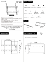
Do the following to assemble the mounting bracket. FIGURE 6-4 and
FIGURE 6-5 show the bracket components and the proper assembly.
1. Remove the components from the shipping bag. To assemble the bracket,
you will need the bottom plate, V-shaped plate, S-shaped plate, three bolts,
two leveling springs, and cylindrical spacer. The bottom plate should come
with three black nylon grommets mounted into it, and the pole mounting
hardware attached to it.
2. Place the leveling springs over the bottom plate’s side grommets.
3. Place the V-shaped plate onto the bottom plate. The V-shaped plate’s legs
should be on the leveling springs and the bubble level should be next to
the pole-mounting hardware.
4. Use two bolts to secure the V-plate legs to the bottom plate (with the
springs sandwiched between the two plates). Initially finger tighten the
bolts and then use a wrench to further tighten them.
Do not compress the springs at this time.
5. Place the cylindrical spacer on the bottom plate’s front grommet.
6. Place the S-shaped plate on the spacer and use the bolt to secure it to the
bottom plate. Initially finger tighten the bolt and then use a wrench to
further tighten. Leave it a bit loose.
CAUTION

CS705 Snowfall Adapter
8
FIGURE 6-4. Exploded view of the CM270 Mounting Bracket Kit
FIGURE 6-5. Two views of an assembled CM270
V-shaped
plate leg
Bubble level
V-shaped
plate
Bolt
Bolt
Leveling
spring
V-shaped
plate leg
Leveling
spring
S-shaped
plate
Grommet
Cylindrical
spacer
Grommet
Bottom
plate
Grommet
Bolt
S-shaped
plate
V-shaped plate
Bottom
plate
Cylindrical
spacer
S-shaped
plate
Cylindrical
spacer
Bottom
plate
V-shaped plate

CS705 Snowfall Adapter
9
Do the following to mount the tipping bucket rain gage to the CM270 bracket
(FIGURE 6-6):
Follow this procedure to ensure that the tipping bucket is mounted
correctly. The adjustment screws for the tipping mechanism will
not be accessible if it is mounted incorrectly.
1. Turn the rain gage upside down and set it on a hard surface such as a table
top.
2. Place the mounting bracket on the bottom of the bucket. Line up the three
holes in the mounting bracket with the three holes used for the mounting
feet. When positioned correctly, the tipping bucket’s cable will be near the
bubble level and pole mounting hardware.
3. Use the three self-tapping screws and a long Phillips screwdriver to
securely fasten the mounting bracket to the bottom of the tipping bucket.
4. Flip the assembly over and tighten the bolt that uses the cylindrical spacer.
The bolts securing the leveling springs need to remain loose to allow
leveling when the bracket is mounted to the pole or mast.
FIGURE 6-6. Mounting CM270 to the rain gage
NOTE
Screws
Mounting holes
Mounting hole

CS705 Snowfall Adapter
10
Attach the mounting bracket/tipping bucket assembly to the mounting pipe or
mast:
1. Install and level the mounting pipe or mast.
2. Loosen the mounting bracket’s wingnuts and slide the assembly over the
pipe. If necessary, the pole mounting hardware can be removed to get the
bolts around the pipe. If this is necessary, to reassemble, put the mast
clamp on first followed by the flat washer, lock washer, and wingnut. See
FIGURE 6-7.
3. Tighten the assembly onto the pipe, while ensuring that nothing is
blocking the top of the rain gage.
4. Adjust the two bolts on the leveling springs until the bubble in the level is
inside the bullseye.
FIGURE 6-7. CM270 pipe mounting (exploded view)
Mast clamp
Lock washer
Bubble level
Flat washer
Wingnut

CS705 Snowfall Adapter
11
6.4 CS705-to-Tipping Bucket Installation Procedure
Equipment required:
• Pail
• TE525WS Texas Electronics Rain Gage
• CS705 Snowfall Adapter
• PGE antifreeze
• Band Clamp (pn 20605)
• Band Clamp (pn 20606)
• Storage Mount (pn 20636)
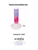
FIGURE 6-8. CS705 mounted to pole using the CM270 Mounting Kit
Band Clamp
(pn 20606)
Storage Mount
(pn 20636)
Band Clamp
(pn 20605)
Catch Tube
Antifreeze
Reservoir
TE525WS
(purchased
separately)

CS705 Snowfall Adapter
12
1. Take one of the black bands supplied with the CS705 and stretch over the
TE525WS funnel (see FIGURE 6-8 and FIGURE 6-9).
FIGURE 6-9. CS705 exploded view
2. Insert the CS705 antifreeze reservoir into the rain gage funnel.
Wear safety glasses during handling and pouring of
antifreeze.
3. Fill the reservoir with PGE antifreeze (pn 10869) until a small amount
flows out the overflow tube. The reservoir holds ≈2.5 gallons.
4. Add ≈8 ounces of a low-freezing-point, environmentally-safe oil to the
antifreeze reservoir. This oil prevents the antifreeze solution from
evaporating. The oil should cover the entire liquid surface. Some
unscented baby oils (lightweight mineral oil) work well.
5. Stretch the second black band over the lip of the antifreeze reservoir.
6. Insert the catch tube into the antifreeze reservoir.
CAUTION
Catch Tube
(pn 13641)
Band
(pn 10786)
Overflow
Tube
(pn 10750)
Antifreeze
Reservoir
(pn 13645)
Entry Seal
(pn 10785)
Band (pn 12319)
/