Page is loading ...

:,
..:,
,..’
3
:
’
.
:
.:
.’
‘..
‘.‘.,
‘.
.’
_-
.
.
.
,-
10
14 15
16
17
27 2823 31
30
5
3
6 7
RR
1884E
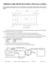
LOCATION OF ELECTRICAL EQUIPMENT
1.
2.
3.
4.
5.
6.
7.
8.
9.
10.
11.
12.
13.
14.
15.
16.
17.
18.
19.
20.
Battery
Air conditioning compressor
Horns
Oil pressure switch
Water temperature switch
Electronic distributor
Alternator
Starter motor
Coil
Relays
Wiper motor-front screen
Relays/delay units
Heater
Window lift motor (front right hand door)
Door lock actuator (front right hand door)
Electronic control unit
Relays
Parking brake warning light switch
Window lift motor (front left hand door)
Door lock actuator (front left hand door)
\
‘,’
13
;1
21.
22.
23.
24.
25.
26.
27.
28.
29.
30.
31.
Seat adjustment
fusebox
Seat motor-relay
Inertia
switch
Window lift motor (rear left hand door)
Door lock actuator (rear left hand door)
Electrical in-tank fuel pump
Window lift motor (rear right hand door)
Door lock actuator (rear right hand door)
Wiper motor-rear screen
Radio aerial amplifier
Fuel filler flap lock actuator
For
fuII
information on
fuel
injection related
items-see fuel injection section of manual.
To identify individual relays (items 10, 12, 17 and
22) see relays in Electrical Section of Manual.
1
..I,
::;..

1987
KAN‘t
ROVER
FAULT DIAGNOSIS
SYMPTOM POSSIBLE CAUSE
CURE
i-Battery
in low
state of charge
1. Broken or loose
connection in
alternator circuit
2. Current voltage regulator
not functioning correctly
3. Slip rings greasy or
dirty.
4. Brushes worn, not fitted
correctly or wrong type
5. Fan belt broken
1. Examine the charging and
field circuit wiring.
Tighten any loose
connections, repair/replace
broken leads. Examine the
battery connection.
2.
Check/fit new unit
3. Clean
4.
Fit new brushes
5. Fit new belt
B-Battery overcharging
leading to burnt
out bulbs and
trequent need for
topping-up
1. Current voltage regulator
not functioning correctly
1. Fit new unit
C-Lamps giving
insufficient
illumination
I.
Battery discharged
2. Bulbs
discoloured
through
prolonged use
3. Fan belt broken
I.
Charge the battery from
independent supply or by a
long period of daylight
running.
2. Fit new bulb
3. Fit new belt
D-Lamps light when
switched on but
fade out
1.
Battery discharged
I.
Charge the battery from
an independent supply or
by a long period of daylight
running
E-Lights flicker 1. Loose connection
1.
Tighten/clean
F-Failure of lights 1. Battery discharged
2. Loose broken connection
3. Fan belt broken
I.
Charge the battery from an
independent supply or by a
long period of daylight
running
1.
Locate and rectify
3. Fit new belt
2

,“..
,
.._..
,
.
.
’
i,
,2.‘,‘.’
‘,
:
.:,
‘,
.’
,
::
‘;
.:
.’
‘.
:
SYMPTOM
POSSIBLE CAUSE CURE
;-Starter motor lacks
power or fails to
turn engine
1. Stiff engine
2. Battery discharged
3. Broken or loose
connection in starter
circuit
4. Greasy or
drrty
skp
rings.
5. Brushes worn, not fitted
correctly or wrong type
6. Brushes sticking in
holders or incorrectly
tensioned.
7. Starter pinion jammed in
mesh with flywheel
I.
Locate cause and remedy
2. Charge the battery either
by a long period of daytime
running or from independent
electrical supply
3. Check and tighten all
battery, starter and starter
switch connections and check
the cables connecting these
units for damage
4. Clean
/
5. Fit new brushes
6.
Rectiiy
7. Remove starter motor and
Investigate
1
H-Starter noisy
1. Starter pinion or
flywheel teeth chipped
or damaged
2. Starter motor loose
on engine
3. Armature shaft bearing
,
1. Fit new components
2. Rectify, checking pinion
and the flywheel for damage
3. Fit new bearing
I-Starter operates
but does not crank
the engine
I. Pinion of starter does
not engage with the
flywheel
1. Check operation of starter
solenoid.
If
correct,
remove starter motor and
investigate
&Starter
pinion will
not disengage from
the flywheel when
the engine is
running
I.
Starter pinion jammed
in mesh with the
flywheel
1. Remove starter motor and
investigate
3

1::
X
.
. .
.
.
.
,:::
‘.
.,..
:
RANGE
lg8’
ROVER
SYMPTOM
POSSIBLE CAUSE
CURE
.-Engine will not
start
1. The starter will not
turn the engine due to
a discharged battery
2. The starter will not
turn due to incorrect
gear selection.
3. Sparking plugs faulty.
dirty or incorrect plug
gaps
4. Defective coil or
distributor
5. A fault in the low
tension wiring circuit
6.
Faultv
amplifier
7. Air gap out of
adjustment
8. Fuel system fault
1.
Recharge battery
by running the car
for a long period during
daylight or from an
independent electrical
supply
2. Select ‘P’ or
‘N’
3. Rectify’ fit new plugs
I
4.
gLv;;
ign;t;ll
checks.
distributor
5. Examine all the ignition
cables and check that the
terminals are secure and
not corroded.
6.
Check/fit
npw
component if
necessary.
7. Adjust
8. See Fuel System Section.
M-Engine misfired
stalls
1. Faulty sparking plugs
2. Air gap incorrectly set
3. Distributor cap cracked
4. Faulty pick-up or
reluctor
5. Excessive wear in
distributor shaft
brushes, etc.
6. Rotor arm and flash
shield cracked or
showing signs of
tracking
1. Rectify
2. Adjust
3. Fit new cap
4. Fit new components
5. Fit a new components
6. Fit new component
_-.-
4

,..”
”
..’
‘.
SYMPTOM
POSSIBLE CAUSE
CURE
&Frequent recharging
of the battery
necessary
1.
Alternator inoperative
2. Loose or corroded
connections
3. Slipping fan belt
4. Voltage regulator
faulty
5. Excessive use of the
starter motor
6. Vehicle operation
confined largely to
night driving
7. Abnormal accessory
load
8. Internal discharge of
the batten,
1. Check the brushes, cables
and connections or fit a new
alternator
2. Examine
ail
connections
especially the battery
terminals and ground
cables
3. Adjust
4. Fit new component
5.
111
the hands of the
operator, advise
6. In the hands of the
operator, advise
7. Superfluous electrical
fittings such as extra
lamps, etc.
8. Fit new battery
I
‘-Alternator
not
charging correctly
1. Slipping fan belt
2. Voltage control not
operating correctly
3. Greasy, charred or
glazed slip rings
4. Brushes worn, sticking
or oily
5.
Shorted, open or burnt
-out field coils
I. Adjust
2. Rectify/ fit new component
3. Clean
4. Rectify/fit new brushes
5. Fit new field coils
3-Alternator
noisy 1. Worn, damaged or
defective bearings
2. Cracked or damaged
pulley
3. Alternator out of
alignment
4. Alternator loose in
mounting
5. Excessive brush noise
I. Fit new bearings
2. Fit new pulley
3. Rectify
4. Rectify
5. Check for rough or dirty
slip rings, badly seating
brushes, incorrect brush
tension, loose brushes and
loose field magnets.
Rectify/fit new components
R-Poor performance
of horns
1. Low voltage due to
discharged battery
2. Bad connections in
wiring
3. Loose mounting nut
4. A faulty horn
1. Recharge
2. Carefully inspect all
connections and horn push
3. Rectify
4. Fit new horn

..:...
,.
,’
.’
,;.:.
.:...
1987
KANGE
ROVER
SYMPTOM
POSSIBLE CAUSE
CURE
S-Central door
locking does not
operate (on all
doors)
1.
Battery discharged
2. Control unit in driver’s
door lock actuator
faulty
3. Loose or broken
connection in driver’s
door
4. Blown fuse
1. Recharge
2. Fit new unit
3. Locate and
rectif)
4. Rectify
T-Central door
locking does not
operate (on one
door only)
1.
Loose or broken
connection
2. Lock actuator failure
3. Faulty lock
4. Mechanical linkages
disconnected
1. Locate and rectii)
2. Fit new actuator
3. Rectify
4. Locate and rectify
U-Window lift will
not
aperate
1. Motor failure
2.
Loose or broken
connection
3. Faulty switch
4. Mechanical linkage
faulty
1. Fit new motor
2.
Locate
and
rectifv
3. Fit new switch
4. Rectify
V-Exterior mirrors
fail to operate
1. Loose or broken
connection
2. Faulty switch
3. Mirror motor failure
I.
Locate and rectify
2. Fit new switch
3. Fit new motor
6

,
‘.
.,...,
.
.
.
,.
.”
‘,..
PO;;;
1987
4
ELECTRICAL
86
;
ELECTRICAL EQUIPMENT
DESCRIPTION
The electrical system is Negative ground, and it is
most important to ensure correct polarity of the
electrical connections at all times. Any incorrect
connections made when reconnecting cables may
cause irreparable damage to the semi-conductor
device?
used in the alternator and regulator.
Incorrect polarity would also seriously damage any
transistorized
equipment such as radio
and
tachometer etc.
WARNING: During battery removal or before
carrying out any repairs or maintenance to
electrical components always disconnect the
battery negative lead first. If the positive read is
disconnected with the negative lead in place,
accidental contact of the wrench to any
grounded metal part could cause a severe spark,
possibly resulting in personal injury. Upon
installation of the battery the positive lead
should be connected first.
ALTERNATOR
-
LUCAS A13380
The alternator is a three phase, field sensed unit.
The rotor and
stator
windings produce three phase
alternating current, AC, which is rectified to direct
current, DC. The electronic voltage regulator unit
controls the alternator output voltage by high
frequency switching of the rotor field circuit. Use
only the correct Range Rover replacement fan belt.
Occasionally check that the engine and alternator
pulleys are accurately aligned.
It is essential that good electrical connections are
maintained at all times. Of particular importance are
those in the charging circuit (including those at the
battery) which should be occasionally inspected to
see that they are clean and tight. In this way any
significant increase in circuit resistance can be
prevented.
Do not disconnect battery cables while the engine
is running or damage to the semi-conductor
devices may occur.
It
is also inadvisable to break or
make any connections in the alternator charging
and control circuits while the engine is running.
The Model 15TR electronic voltage regulator
employs micro-circuit
techniques resulting in
improved performance
under difficult service
conditions. The whole assembly is encapsulated in
silicone rubber and housed in an aluminium heat
sink, ensuring complete protection against the
adverse effects of temperature, dust. and moisture
etc.
<
1:
The regulating voltage is set during manufacture to
give the required regulating voltage range of 14.2
;:I$
‘,
+
0.2 volts, and no adjustment is necessary. The only
maintenance needed is the occasional check on
terminal connections and wiping with a clean dry
cloth.
The
alternatn:
svstem
provide<
for direct
connecuon
OI
a charge
(ignition)
indicator warning
light, and eliminates the need for a field switching
relay or warning light control unit. As the warning
lamp is connected in the charging circuit, lamp
failure will cause loss of charge. Lamp should be
checked regularly and a spare carried.
When using rapid charge equipment to re-charge
the battery, the battery must be disconnected from
the vehicle.
REVISED: SEPT. 87
7
.:
\.’

RANGE
lg8’
ROVER
ALTERNATOR
Remove and refit
Removing
ALTERNATOR DRIVE BELT
-
Adjust
1. Loosen
the alternator fixings and the
adjustment link.
1.
Disconnect battery ground lead.
2. Pivot the alternator to give the required belt
2. Disconnect leads from alternator.
tension.
3. Belt tension should be 4 to 6mm (0.19 to 0.25
in) at the point indicated by the bold arrow.
3. Loosen alternator fixings, pivot alternator
inwards and remove drive belt.
4. Remove three mounting bolts and lift the
alternator clear of the engine.
4.
Tighten the alternator fixing bolts and the
adjustment link.
Refitting
5. Fit the alternator and mounting bolts.
NOTE: Check adjustment after running
engine at fast idle speed for
3
to 5 minutes
if a new belt has been fitted.
NOTE: The fan guard is attached to the
front fixing and the adjustment bracket
bolt.
6. Fit the drive belt and adjust the belt tension.
7. Tighten
the
mounting
bolts and the
adjustment bracket securing nut.
8. Connect the wiring leads
tci
the alternator.
9. Connect the battery.
.-
.
REVISED: SEPT. 87

:
:.
:
‘.,’
.,
:,;.::
,:
.
.I.
.‘,
.
,
ELECTRICAL
86
l-l
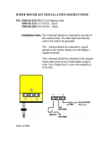
ALTERNATOR-LUCAS-TYPE A13380
1.
Cover
2.
Regulator
3.
Rectifier
4. Drive end bracket
5.
Bearing assembly
‘6. Rotor
7. Slip ring end bearing
8.
Slip rings
9.
Slip ring end bracket
10.
Stator
11.
Brush box
12.
Brushes
13. Through bolts (three)
14.
Suppressors
REVISED: JULY 88
9

.
.,
ALTERNATOR-LUCAS-TYPE
A133/80
Overhaul
Including Test (Bench)
NOTE: Alternator charging circuit-The ignition
warning light is connected in series with the
alternator field circuit. Bulb failure would
prevent the alternator charging, except at very
high engine speeds, therefore, the bulb should
be checked before suspecting an alternator
failure.
Precautions
Battery polarity is NEGATIVE GROUND, which must
be maintained at all times.
No separate control unit is fitted; instead a voltage
regulator of
micro-circuit
construction is
incorporated on the slip ring end bracket, inside
the alternator cover.
Batters
voltage is
apnlied
to the alternator
outout
cable
even when the
ignrtron
is
swrtched
off, the
batteT
must be disconnected before commencing
any work on the alternator. The battery must also
be disconnected when repairs to the body structure
are being carried out using electric welding
equipment.
Sequence of connections
RR1841E
?
Suppression
capacrtors
(two)
2.
Positrve
suppression terminal
3. IND terminal
4. + output terminal
5. Sensing terminal
‘.
.,
.,
.,:.
10 REVISED: JULY 88

ALTERNATOR TESTING
Charging system check
1. Check the battery is in good condition, with
an open circuit voltage of at least 12.6 V.
Recharge or fit a charged substitute battery to
carry out test.
2. Check drive belt adjustment and condition.
Rectify as necessary.
3. Check battery connections are clean and tight.
4. Check alternator connections are clean and
tight.
5. Ensure that there is no continuous drain on
battery due, for example, to interior,
underhood or door edge lamps being left on.
Alternator test
The following instructions refer to the use of
suitable test- equipment using a carbon pile
rheostat.
Testing-alternator removed
11.
12.
13.
Withdraw the connectors from the alternator.
Remove the alternator.
Disconnect the suppressor and remove the
alternator cover.
6.
7.
8.
.
:
..:;.
9.
10.
Connect test
equrpment
referring to the
manufacturer’s instructions.
Start engine and run at 3000
rev/min
without
accesory
load.
Rotate the carbon pile load control to achieve
the greatest output (amps) without allowing
voltage to fall below 12.0 V. A reading of 80
amps, minus 10% to allow for EFI and Ignition
loss, should be obtained.
Run engine at 3000 rev/min, switch selector to
regulator test, read voltmeter. A reading of
13.6 to 14.4 V should be obtained.
Switch selector to diode/stator test, switch on
headlamps to load alternator. Raise engine
speed to 3000 rev/min, read voltmeter. The
needle must be within the
IOK’
range.
NOTE: See also charging circuit resistance test,
page 13.
14.
15.
16.
17.
18.
19.
20.
'1.
Disconnect the lead and remove the rectifier
assembly.
Note the arrangement of the brush box
connections and remove the screws securing
the regulator to the brush box and withdraw.
This screw also retains the inner brush
mounting plate in position.
Remove the screw retaining the outer brush
box in position and withdraw both brushes.
Check brushes for wear by measuring length
of brush protruding beyond brush box
moulding.
If length is
10mm
(0.4 in) or less, fit
new brushes.
Check that brushes move freely in holders. If
brush is sticking, clean with a mineral spirit
moistened cloth or polish sides of brush with
fine file.
Check brush spring pressure using push-type
spring gauge.
Gauge should register 136 to
279s
(5 to 10 oz) when brush is pulled back
until face is flush with housing. If reading is
outside these limits, fit a new brush assembly.
Remove the two screws securing the brush
box to the slip ring end bracket and lift off the
brush box assembly.
Securely clamp alternator in a vice and release
the
stator
winding cable ends from the
rectifier
bv
applying a hot soldering iron to the
terminal tags
ot
the rectifier. Pry out the cable
ends when the solder melts.
REVISED: SEPT. 87
11
:a

.”
;:,
.,
.‘.’
:
”
.,..y.
;:’
‘.
.I.
:,,
‘.
;
.
‘)
i
:
‘.
:’
..:
j:;
X
1987
&INCt
ROVER
22.
23.
Remove the two remaining screws securing
the rectifier assembly to the slip ring end
bracket and lift off the
rectifier
assembly.
Further dismantling of the rectifier is not
required.
Check
the
diodes.
Connect the test
equipment as shown and test each diode in
turn, note whether lamp lights, then reverse
test iead connections. The lamp should light in
one direction only. Renew the rectifier
assembly if a faulty diode is diagnosed.
RR22BOE
24.
25.
Remove the slip ring end bracket bolts and lift
off the bracket.
Connect a
12
volt battery and a 36 watt test
lamp to two of the
stator
connections. Repeat
the test replacing one of the two
stator
connections with the third. If test lamp fails to
light in either test, fit a new
stator.
RR228i3E
’
25’
26. Using a 110 volt
a.c.
supply and a 15 watt test
lamp, test for insulation between any one of
the three
stator
connections and
stator
laminations.
If
test lamp lights, fit a new
stator.
27.
28.
29.
30.
Clean surfaces of slip rings using a solvent
moistened cloth.
inspect slip
ring
surfaces tor signs of burning;
remove burn
mark<
using
vers
fine sandpaper
On no account should emery cloth or similar
abrasives be used, or any attempt made to
machine the slip rings.
Note the position of the
stator
output leads in
relation to the alternator fixing lugs, and lift
the
stator
from the drive end bracket.
Connect an ohmmeter to the slip rings. A
reading of 2.6 ohms should be recorded.
31. Using a 110 volt
a.c.
supply and a 15 watt test
lamp, test for insulation between one of the
slip rings and one of the. rotor poles. If the
test lamp lights, fit a new rotor.
.
:
,.
,.
--...
;
,
:
‘.
“,.._
12
REVISED: SEPT. 87

32. To separate the drive end bracket and rotor,
remove the shaft nut, washers, woodruff key
and spacers from the shaft.
33. Remove bearing retaining plate by removing
the three screws. Using a press, drive the
rotor shaft from the drive end bearing.
34.
ff
necessary, to remove the slip rings or the
slip ring end bearing on the rotor shaft,
unsolder the outer slip ring connection and
gently pry the slip ring off the shaft, repeat the
procedure for the inner slip ring connection.
Using a suitable extraction tool, withdraw the
slrp
ring bearing from the shaft.
Reassembling
35. Reverse the dismantling procedure, noting the
following points.
(a) Use Shell Alvania
‘RA’
to lubricate
bearings.
(b) When refitting slip ring end bearing,
ensure it is fitted with open side facing
rotor.
(c) Use
Fry’s
H.T.3 solder on slip ring field
connections.
(d)
When refitting rotor to drive end bracket,
support inner track of bearing. Do not
use drive end bracket to support bearing
when fitting rotor.
(e)
Tighten through-bolts evenly.
(f) Fit brushes into housings before fitting
brush moulding.
(g)
Tighten shaft nut to the correct torque,
see Torque Values.
(h)
Refit regulator pack to brush moulding.
36. Reconnect the leads between the regulator,
brush box and rectifier.
37. Refit the alternator.
Testing in position
Charging circuit resistance test.
I. Connect a low range voltmeter between the
alternator terminal marked + and the positive
terminal of the battery.
/
RR2317t
2. Switch on the headlamps and start the engine.
Set the throttle to run at approximately 3000
rev/min.
Note the voltmeter reading.
3. Transfer the voltmeter connections to the
frame of the alternator and the negative
terminal of the battery, and again note the
voltmeter reading.
RR2318E
4. If the reading exceeds
0.5
volt on the positive
side or 0.25 volt on the negative side, there is
a high resistance in the charging circuit which
must be traced and remedied.
REVISED: SEPT. 87
13

bl
ELECTRICAL
1987
K”d;i;
BATTERY
Remove and refit
Remove and refit
WARNING: During battery removal or before
carrying out any repairs or maintenance to
electrical components always disconnect the
battery negative lead first. If the positive lead is
disconnected with the negative lead in place,
accidental contact of the wrench to any
grounded metal part could cause a severe spark,
possibly resulting in personal injury. Upon
installation of the battery the positive lead
should be connected iirst.
HORNS
Removing
1. Disconnect battery ground lead followed by
the disconnection of the positive lead.
2. Release the four nuts securing the battery
bracket in position.
3. Remove the bracket from the studs.
4
Remove-
the batten,
NOTE:
Twin
horns
are
fitted. An
identification letter is stamped on the front
outer rim of the horn;
‘HI-high
note,
IL’-low
note.
Removing
1. Disconnect the battery negative lead.
2. Remove radiator grille.
3. Remove the nut and withdraw the horn.
4. Disconnect the electrical leads.
5. Remove the plain and serrated washer.
--------
RR669M
-
Refitting
5. Reverse the removal procedure.
NOTE:
Coat the battery clamps and
terminals with petroleum jelly before
refitting.
Refitting
NOTE: When refitting the horn ensure that
the stud location is pushed firmly to the
back of the elongated slot to prevent the
horn fouling the radiator grille.
6. Reverse removal procedure.
”
/
REVISED: SEPT. 87

1
DISTRIBUTOR-LUCAS 35
DLMB
SERVICE PARTS
1.
3.
I
1
::
6.
9.
Cap
HT brush and spring
Rotor arm
Insulation cover
Pick-up module and base plate assembly
Vacuum unit
Amplifier module
‘0’~ring
oil seal
Gasket
.
.
2
3
4

,’
.”
’
:
:.
1::.
,”
.,.:
:,
I
.
.
.
,
“.‘.;,
..‘. .
...‘.
L
ELECTRONIC IGNITION
A Lucas
35DLMB
distributor is employed. This has a
conventional vacuum advance unit and centrifugal
automatic advance mechanism.
A pick-up module, in conjunction with a rotating
timing reluctor
inside
the distributor body,
generates timing signals. These are applied to an
electronic ignition amplifier module mounted on
the side of the distributor body.
NOTE: The pick-up air gap is
fgctory
set. Do
not adjust the gap unless the pick-up IS
being changed or the base plate has been
moved. Use a non-ferrous feeler gauge to
set the air gap.
DISTRIBUFOR
Remove and refit
Removin,?
1. Disconnect the battery
neghkive
lead.
2. Disconnect the vacuum hose.
3. Remove the distributor cap.
4. Disconnect low tension lead from the coil.
5. Mark distributor body in relation to centre line
of rotor arm.
NOTE: Marking distributor enables refitting
in exact original position, but if engine is
turned
while distributor is removed,
complete ignition timing procedure must be
followed.
7. Release the distributor clamp and remove the
distributor.
Refittin:
NOTE: If a new distributor is being fitted,
mark body in same relative position as
distributor removed.
6. Add alignment marks to distributor and front
cover.
8. Leads for distributor cap should be connected
as illustrated.
Figures
I
to
8
inclusive indicate plug lead
numbers.
RH-Right hand side of engine, when viewed
from the rear.
LH-Left hand side of engine, when viewed
from the rear.
16

,
ELECTRICAL
86
9. If engine has not been turned while distributor
has been removed, proceed as follows (items
10
to 17). Alternatively proceed to instruction
18.
10.
Fit new ‘0’ ring seal to distributor housing.
11. Turn distributor drive until centre line of rotor
arm is 30” counter- clockwise from mark made
on top edge of distributor body.
12.
Fit distributor in accordance with alignment
markings.
NOTE: It may be necessary to align oil
pump drive shaft to enable distributor drive
shaft to engage in slot.
13.
Fit clamp and bolt. Secure distributor in exact
original position.
14.
Connect vacuum hose to distributor and low
tension lead to coil.
15. Fit distributor cap.
16. Reconnect battery.
17. Using suitable electronic
equipme
II8
, set the
ignition timing, see IGNITION TIMING-Adjust.
18. If, with distributor removed, engine has been
turned it will be necessary to carry out the
following procedure.
19. Set engine-No. 1 piston to static ignition
timing figure (see Engine Tuning Data- Section
05) on compression stroke.
20. Turn distributor drive until rotor arm is
approximately 30” . counter-clockwise from
number one sparking plug lead position on
cap.
21.
Fit distributor to engine.
22. Check that centre line of rotor arm is now in
line with number one sparking plug lead on
cap. Reposition distributor if necessary.
23. If distributor does not seat correctly in front
cover, oil pump drive is not engaged. Engage
by lightly pressing down distributor while
turning engine.
24. Fit clamp and bolt leaving both loose at this
stage.
25. Set the ignition timing statically to 6” B.T.D.C.
26. Connect the vacuum hose to the distributor.
27. Fit low tension lead to coil.
28. Fit
drstributor
cap.
29. Reconnect the battery.
30. Using suitable electronic equipment set the
ignition timing, see IGNITION TIMING-Adjust.
DISTRIBUTOR-LUCAS 35DLM8
Overhaul
DISTRIBUTOR CAP
1. Unclip and remove the cap
2. Fit a new cap if known to be faulty.
3. Clean the cap and HT brush with a lint free
cloth.
REVISED: JUNE 87
ROTOR ARM
4. Pull rotor arm from shaft.
5. Fit a new rotor arm if known to be faulty.
INSULATION COVER (Flash shield)
6. Remove cover, secured by three screws.
7. Fit a new cover if known to be faulty.
VACUUM UNIT
8. Remove two screws from vacuum unit
securing bracket, disengage vacuum unit
connecting rod from pick-up base plate
connecting peg, and withdraw vacuum unit
from distributor body.
Continued
17
;

86
ELECTRICAL
RANGE
lg8’
ROVER
AMPLIFIER MODULE
FIlTlNC
PICK-UP AND BASE PLATE ASSEMBLY
9.
10.
11.
Remove two screws and withdraw the module.
Remove the gasket.
Remove two screws securing the cast
heatsink
and remove the heatsink.
WARNING: The amplifier module is a sealed
unit containing Beryllia. This substance is
extremely dangerous if handled. Do not
attempt to open or crush the module.
PICK-UP AND BASE PLATE ASSEMBLY
12.
13.
14.
15.
16.
Use circlip pliers to remove the circlip
retaining the reluctor on rotor shaft.
Remove the fiat washer and then the
‘0’
ring
recessed in the top
01
the reluctor.
Gently withdraw the reluctor from the shaft,
taking care not to damage the teeth.
NOTE:
Coupling
ring fitted beneath
reluctor.
Remove three support pillars and cable
grommet. Lift out the pick-up and base plate
assembly.
NOTE: Do not disturb the two barrel nuts
securing the pick-up module, otherwise the
air gap will need re-adjustment.
Fit a new pick-up and base plate assembly if
module is known to be faulty, otherwise check
pick-up winding resistance (2k-5k ohm).
RE-ASSEMBLY
17. This is mainly a reversal of the dismantling
procedure, noting the following points:
LUBRICATION
Apply clean engine oil:
a.
A spot into the rotor spindle before
fitting rotor arm.
Apply Omnilube 2 (or equivalent) grease.
18
REVISED: JUNE 87
b.
Auto advance mechanism.
::
Pick-up plate centre bearing.
Pre tilt spring and its rubbing area
(pick-up and base plate assembly).
e.
Vacuum unit connecting peg (pick-up
and base plate assembly).
f.
The connecting peg hole in vacuum unit
connecting rod.
18.
Pick-up leads must be prevented from fouling
the rotating reluctor. Both leads should be
located in plastic guide as illustrated. Check
during re-assembly.
REFITTING
RELUCTOR
lo
Slide
reklctor
a<
fa:.
ai
ii
Lvili
go on
rotor
shafi
then rotate reluctor- until it engages with the
coupling ring beneath the pick-up base plate.
The distributor shaft, coupling ring and
reluctor are ‘keyed’ and rotate together. Fit
the
‘0’
ring, flat washer and retaining circlip.
PICK-UP AIR GAP
ADjUSTMENT
..
.,
20. The air gap between the pick-up limb and
reluctor teeth must be set within the specified
limits, using a non-ferrous feeler gauge.
21. If adjustment is necessary, slacken the two
barrel nuts to set the air gap. See Engine
Tuning Data.
. . . .
,
1
.,
‘,
b

‘..
.:
.-
ELECTRICAL
86
f-l
NOTE: When the original pick-up and base plate
assembly has been refitted the air gap should be
checked, and adjusted if necessary.
When fitting a new assembly the air gap will
require adjusting to wittiin the specified limits.
AMPLIFIER MODULE
22. Before fitting the module, apply MS4 Silicone
grease or
equivalent heat-conducting
compound to the amplifier module backplate,
the seating face on distributor body and both
faces of the
heatslnk
casting.
IGNITION COIL
Remove and refit
Removing
I. Disconnect the battery negative terminal.
2. Disconnect the
H@h
Tension and Low Tension
electrical leads
from
the Ignition
coil.
3. Remove the two bolts securing the coil to the
valance.
NOTE: A ground strap is located under one
of the bolts.
4. Remove the
coil from the engine
compartment.
Refitting
5. Reverse the removal instructions.
NOTE: Ensure that the bolting location for
the ground strap is free from paint and
grease. Coat the area around the bolt with
Petroleum Jelly.
IGNITION TIMING
Adjust
It
is essential that the following procedures are
adhered to. Inaccurate timing can lead to
serious engine damage and additionally create
failure to comply with emission regulations. If
the engine is being checked in the vehicle, the
air
conditioning
compressor
must be
disengaged.
On initial engine build, or if the’ distributor has
been
dlsrurbed
tor any reason, the ignition
timin?
muqt
be set
statlcallv
to 6’ B T.D.C.
(This
sequence is to
gwe
only an
approximation in order that the engine may be
started) ON NO ACCOUNT MUST THE
ENGINE BE
STARTED BEFORE
THIS
OPERATION IS CARRIED OUT.
Equipment required
Calibrated Tachometer
Stroboscopic lamp
3
4
5.
6.
7.
Couple
stroboscopic
timing
lamp and
tachometer to
engine following
the
manufacturer’s instructions.
Disconnect the vacuum hose from the
distributor.
Start engine, with no load and not exceeding
3,000
rev/min
run engine until normal
operating temperature is reached. (Thermostat
open). Check that the normal idling speed falls
within the tolerance specified in the data
section.
Idle
speed for timing purposes must not
exceed 800
rev/min.
With the distributor clamping bolt loosened
turn distributor until the timing flash coincides
with the timing pointer and the correct timing
mark on the rim of the torsional vibration
damper as shown in the engine tuning
section.
Continued
REVISED: MAY 89
19

1987
RANGE
ROVER
8.
9.
10.
Retighten
the distributor
clamping bolt
securely. Recheck timing in the event that
retightening has disturbed the distributor
position.
Refit vacuum hose.
Disconnect stroboscopic timing lamp and
tachometer from engine.
LUCAS CONSTANT ENERGY IGNITION SYSTEM
35DLMlbPRELIMINARY CHECKS
Inspect battery cables and connections to ensure
they are clean and tight. Check battery state of
charge it in doubt as to its condition.
Inspect all L.T. connections to ensure that they are
clean and tight. Check the H.T. leads are correctly
posltioned
and not
shorting
to ground
agaIns
any
enFine
components. The wirinq harness and
Individual cables
shoula
be
hrmly
tastened
to
prevent chaffing.
PICK-UP AIR CAP
Check the air gap between pick-up limb and
reluctor teeth, using a non-ferrous gauge, see
‘Engine Tuning Data’.
NOTE: The gap is set initially at the factory and
will only require adjusting if tampered with or
when the pick-up module is replaced.
TEST 1:
H.T. Sparking
Remove coil/distributor H.T. lead from distributor
cover and hold approximately
6mm
(0.25 in) from
the engine block, using suitable insulated pliers.
Switch the ignition ‘On’ and operate the starter.
Regular sparking indicates fault in H.T. distribution,
plugs, timing or
fueliing,
proceed to Test 6. If no
spark or weak spark occurs proceed to Test 2.
,
Test 2:
LT.
Voltage
Switch the ignition ‘On’
-
engine stationary.
(a)
Connect voltmeter to points in the circuit
indicated by VI to V4 and make a note of the
voltage readings.
(b)
Compare
voltapes
obtained with the
specitied
values listed below:
EXPECTED READINGS
Vl
v2
v3
v4
(c)
(d)
More than 12 volts.
1 volt maximum below volts at
Vl.
1 volt maximum below volts at
Vl.
0 volt
-
0.1 volt.
(e)
If all readings are correct proceed to Test 3.
Check incorrect reading(s) with chart to
identify area of possible faults, i.e. faults listed
under heading SUSPECT and rectify.
If coil and amplifier is suspected, disconnect
L.T. lead at coil, repeat V3. If voltage is still
incorrect, fit new coil. If voltage is now
correct, check L.T. lead, if satisfactory fit new
amplifier.
(0
If engine will not start proceed to Test 3.
.._
.
I
20
REVISED: MAY 89
:’
/