Page is loading ...

;;;f;
1987
CHASSIS AND BODY
‘%
BODY REPAIRS, GENERAL INFORMATION
Welding
The Range Rover body consists of a steel frame to
which alloy outer panels are attached. The cowl
panel, front fenders, side door outer panels, body
side outer panels and roof are made from a special
light magnesium-aluminium alloy.
The manufacture of body panels from aluminium
has two distinct advantages, the first of which is a
much better resistance to corrosion, the second
being a decrease in the gross vehicle weight.
Aluminium panels can be effectively repaired using
the ‘Argon Arc
’
process of welding, because the
afore
mentioned is a specialist operation it is
necessary that only a skilled operator or specialist
body shop undertake such repairs.
.:
Under certain conditions it may’ not be practical to
repair an exterior damaged panel, if this is the case,
then panels can be easily removed and replaced
with new ones (refer to the appropriate part of the
Body section for panel removal and refit).
Panel beating
.T..
1. Aluminium alloy panels can be beaten out
after accidental damage in the same way as
sheet steel. However, under protracted
hammering the material will harden, and then
it must be annealed to prevent the possibility
of cracking. This is quite easily done by the
application
of heat,
followed by slow
air-cooling, but as the melting point is low,
heat must be applied slowly and carefully.
CAUTION: Before applying heat to any panel
ensure that the panel is clean and free from
underseal and that the area to be worked on is
well clear of any combustible materials. Ensure
that all necessary precautions are taken against
fire. IF HEAT IS TO BE APPLIED TO THE REAR
RIGHT HAND FENDER, THE FENDER MUST FIRST
BE REMOVED AS A FUEL EXPANSION TANK IS
LOCATED BETWEEN THE FENDER AND INNER
BODY SIDE.
CAUTION: The battery ground lead MUST be
disconnected before commencing welding. IF
WELDING IS TO BE CARRIED OUT ON THE REAR
RIGHT HAND FENDER, THE FENDER MUST BE
REMOVED, AS A FUEL EXPANSION TANK IS
LOCATED BETWEEN THE FENDER AND INNER
BODY SIDE.
1. Clean off all grease and paint, dry thoroughly
and then clean the edges to be welded, and
an area at least half an inch on either side of
the weld, with a stiff wire scratch brush or
wire wool. Cleanliness is essential. Also clean
the welding rod or strip with steel wool.
2. It is strongly recommended that a few welds
are made on scrap metal before the actual
repair is undertaken if the operator is not
already experienced in welding aluminium and
its alloys.
3. Use only 5 per cent magnesium aluminium
welding rod (5
Mg/A).
Welding tears and patching
1. If a tear extends to the edge of a panel, start
the weld from the end away from the edge
and also at this point drill a small hole to
prevent the crack spreading, then work
towards the edge.
2. When welding a long tear, or making a long
welded joint, tack the edges to be welded at
intervals of from 2 in to 4 in (50 to
100mm)
with spots. This is done by melting the metal
at the starting end and fusing into it a small
amount of the filler rod, repeating the process
at the suggested intervals. After this, weld
continuously along the joint from right to left,
increasing the speed of the weld as the
material heats up.
3. When patching, cut the patch to the correct
shape for the hole to be filled, but of such
sizes as to leave a gap of
l/32
in
(0.80mm)
between it and the panel, and then weld as
described above. Never apply an ‘overlay’
patch.
1
.‘,

76
‘CHASSIS AND BODY
1987
RANGE
ROVER
c
.
Spot welding
. 1. spot
welding
is
mainly
used
in
the
manufacture of the Range-Rover inner steel
body frame and exterior magnesium-aluminium
alloy panels, and is a process which can be
carried out satisfactorily by the use of the
proper apparatus in a specialist body shop.
Aluminium and its alloys are very good
conductors of heat and electricity, and thus it
is most important to maintain the right
conditions for successful spot welding. The
correct current density must be maintained,
and so must the ‘dwell’ of the electrodes.
Special spot welding machines have been
developed, but they are expensive, and
though the actual work can be carried out by
comparatively unskilled
labour,
supervision and
machine maintenance must be in the hands of
properly qualified persons.
Riveting
1. Where both sides of the metal are accessible
and it is possible to use an anvil or ‘dolly’
solid aluminium rivets may be used, with a
suitable punch or ‘pop’ to ensure clean
rounded head on the work. For riveting blind
holes, ‘pop-rivets’ must be used. These are
inserted and closed by special
‘Lazy-Tong’
‘pop-rivet’ pliers.
2
PAINTWORK
General Information
Before undertaking any paintwork process on the
exterior body of Range Rover, firstly ascertain which
is the best method of repair either by panel repair
or replacement.
The initial preparation of a panel is very important
to ensure that when finished it is of a standard that
meets and matches existing bodywork. Panels must
be thoroughly degreased with Berger Preclean
802.0516 or a suitable equivalent, any unsound
paint to be stripped using Berger Double strength
Meltic
301.8051. Always refer to the paint
manufacturers instructions.
Paintwork processes should be performed by a
specialist
bodyshop
where paint spraying can be
undertaken in a controlled environment whereby
temperatures are kept constant and the atmosphere
dust free.
The flow chart on the following page gives a guide
to preparing and painting a panel. Wherever
possible refer to the Berger Vehicle Refinishes
Product Data and Application Sheets for further
information.
j

RANGE
1987
ROVER
CHASSIS AND BODY
SUBSTRATE
ALUMINIUM
PANELS
I
I
I
PANEL REPAIR
REPLACEMENT PANEL
‘REPARATION
Vet for using
P60
Grade paper or dry
and using
P240
grit discs.
Wet flat using
P60
Grade paper or dry
sand using
P240
grit discs. Care must
be taken to
avord
cutting through to
bare aluminium.
lODY
FILLING
f filling is required, thoroughly
lbrade
bare
alumrnium
area to be
illed
and apply
Standox
Polyester
Jopper
430-5029.
If filling is required, fill small
indentations with
Standox
Polyster
stopper
430-5029.
iTCHlNG
itch the bare aluminium and filler
This process is not required if the
with
auto-speed self etch
original electrocoat primer is in
lrimer
414-1171, mixed
1:l
with
actrvator
301-7995.
Apply one coat and
-1
;;;zzondition.
allow
to dry for approximately 20
ninutes.
Zecoat
within
1
hour.
1
‘RIMING
To obtain maximum adhesion and excellent build, apply
Standox
2K
4:l
full primer
405-0381.
Coats of 30-40 microns can be wet
flatted with
P60
grade paper after 45 minutes at 20°C.
COLOUR COATING
Apply either
Standox
2K Standocryl or
Standox
Metallic Basislack
,,
to the
colour
required. Hardeners and
thrnners
will
var)
depending upon system employed, conditions available,
temperature and size of vehicle etc. Refer to paint manufacturers
Technical Information Sheet for correct selection.
REVISED: MARCH 90

:
.I.>
.I
.
.
RANGE
CHASSIS AND BODY
1987-90
ROVER
REVISED: APR. 87

.
.
.
.
‘.
:.:.:..
..
;“o”;;
1987-90
CHASSIS AND BODY
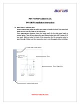
CHASSIS FRAME
Alignment check
AA
BB
cc
DD
EE
FF
1
2
3
4
5
6
7
8
9
10
11
12
13A
138
14
15
16
17
18
19
20
21
22
23
24
25
26
27
28
29
30
31
Diagram reference
millimetres
inches
Wheelbase-Reference dimension
Centre line of front axle
Centre line of rear axle
Frame datum line
Side member datum line
Datum line
(with mounting washers)
(without washers)
Reference dimension
To face of boss
Frame datum to underside of cross-member
Check figure
2540.00 100.000
254.00
+
0.63
10.000
+
,025
263.525 + 1.91
10.375 +
,075
-
0.63
-
,025
261.11
2
2.54
10.180
+
.I00
266.70
+
2.54
10.500
2.100
237.74
4
1.27
.9.360
+
,050
327.81
f-
2.54
12.906 -f
.I00
979.93
+
1.27
38.580
2.050
2244.72
+
2.54
88.375
+
.I00
356.74
+
2.54
14.045
+.100
605.15
+
2.54
23.825
+.I00
1405.38
+
2.54
55.330
+-loo
694.44
+
2.54
27.340
+.I00
338.83
+
2.54
13.340
+.100
222.25
2
5.08
8.750
2.200
240.54
+
2.54
9.470
L.100
794.91
31.296
935.43
L
2.54
36.828
+.100
150.79
5.937
535.94
+
2.54
21.100
~.I00
590.55
+
0.64
23.250
2.025
630.93
~1.27
24.840
2.050
344.17
+
1.27
13.550
+.050
485.77
f
2.54
19.125
+
.I00
485.77
+
2.54
19.125
+
.I00
414.32
+
2.54
16.312
+.I00
.
129.03
+
2.54
5.080
+.I00
2544.44
+
0.25
100.175
2.010
1355.34
+
0.38
53.360
2.015
1722.04
+
0.38
67.797
2.015
2663.44
+
0.38
104.860
+.015
144.09
2
0.38
5.673
+.QlS
400.48
fL
2.54
15.767
+.lOO
1333.88
+
0.38
52.515
2.015
Continued
5
"
:

RANGE
CHASSIS AND BODY
1987-90
ROVER
.c,.
‘.’
32
Reference dimension
33
Reference dimension
34
Reference dimension
SECTION XX
35
Frame datum line DD
36
37
SECTION
W
38
Frame datum line DD
39
40
SECTION ZZ
41
Frame datum line DD
42
43
44
millimetres
925.49
36.437 .
..
147.62
5.812
635.00
25.000
488.95
r.
2.54
295.27
2
2.54
660.40
+
0.17
MO.95 + 1.91
-
0.63
80.95
+
1.91
-
0.63
660.4
+
0.17
9.525
+
2.54
inches
19.250
+
.lOO
11.625
2.100
26.000
L.007
3.187 +
.075
-.025
3.187 +
.075
-.025
26.000
_+_.007
0.375
&.I00
:
,:_.

,.
.’
CHASSIS AND BODY
(76
1
BODY
Introduction:
The information which follows is concerned solely
with the ‘Monocoque’ assembly of the inner body
shell on Range Rover models.
Body
repairs
often require the removal of
mechanical and electrical units and associated
wiring. Where necessary, reference should be made
to the relevant section of the Repair Manual for
removal and refitting instructions.
The inner body shell is of ‘Monocoque’
construction and to gain access to the repair area, it
may be necessary to remove exterior body panels,
all exterior body panels are bolted to the inner
body shell to facilitate easier panel removal and
replacement or repair.
It is expected that a repairer will select the best and
most economic repair method possible, making use
of the facilities available. The instructions given are
intended to assist a skilled body repairer by
expanding
approved
procedures for
panel
replacement with the objective of restoring the car
to a safe running condition and effecting a repair
which is visually acceptable.
WELDING
The following charts and illustrations show the
locations and types of weld for securing the body
side assembly, tailgate frame assembly and the front
valance
and
wheel
arch
assembly.
Before
undertaking any spot weld joints to the inner body,
it is advisable to make a test joint using
offcuts
of
the damaged components, and to use this test
piece to perform a weld integrity test.
Spot welding is satisfactory if the joints do not pull
apart. If the weld pulls a hole or tears the metal the
weld is satisfactory. It is defective if the weld joint
pulls apart or if there are signs of burning, porosity
or cracking evident.
PREPARATION
Thoroughly clean all areas to be welded, remove
any sealants and corrosion protectives from around
original panels. Align and clamp all new panels in
position and check relationship to one another.
Continued
7

l-l
76
CHASSIS AND BODY
RANGE
1987-90
ROVER
INNER BODY SHELL ASSEMBLY
LOCATION
FACTORY JOINT (minimum number of
spot welds quoted)
A.
Front cross
member
to
valance and wheel arch
assembly
6 spot welds, 20mm pitch
B.
Hood locking platform to
valance and wheel arch
assembly
10 spot welds, 25mm pitch
C.
Valance and wheel arch
assembly to dash and tunnel
assembly
16 spot welds, 25mm pitch
0.
Body side complete to dash
IO
spot welds, 65mm pitch
and tunnel assembly

R”o”v‘;l:
7
987-90
CHASSIS
ANn
Rnnv
hiI
./.:
:.
.
:.:::
1..
.,
.
.
.
.
.
...*
.,:.
:
.;
LOCATION E
LOCATION
E.
1. Body side complete to
heelboard panel assembly.
2. Body side complete to
dash and tunnel assembly
complete.
3. Body side complete to dash
and tunnel assembly
-.
I. Body side complete to
dash and tunnel
assembly complete
2. Body side complete to
dash and tunnel
assembly complete
3. Body side complete to
dash and tunnel
assembly complete
LOCATION F
FACTORY JOINT (minimum number of
spot welds quoted)
14
spot welds,
35mm
pitch
10 spot welds, 25mm pitch
3 spot welds, 30mm pitch
7 spot welds,
30mm
pitch
18
spot welds, 40mm pitch
30 spot welds, 34mm pitch
Continued
9

.I
76
CHASSIS AND BODY
RANGE
1987-90
ROVER
LOCATION
C
LOCATION H
LOCATION
FACTORY JOINT (minimum weld
requirement quoted)
G.
1.
Reinforcement plate to
dash and tunnel assembly
CO, weld, 2 places 75mm long
each weld
and body side assembly
complete
H. 1. Body side complete to roof
header panel assembly
(internal joint)
3 spot welds, 15mm pitch
2. Body side complete to roof
header panel assembly
(internal joint)
3 spot welds,
15mm
pitch
;:

.‘.
LOCATION
J
LOCATION
I.
1. Body side complete to rear
tailgate frame assembly
K.
1. Body side complete to roof
header panel assembly
(external joint)
2. Body side complete to roof
header panel assembly
(external joint)
LOCATION K
FACTORY JOINT (minimum weld
requirement quoted)
CO?
weld, one run 40mm long
CO?
weld, one run 20mm long
CO*
weld, one run
100mm
long
Continued
11

I
:..
‘.
.
..’
‘.
..,.,.
:.:
l-l
76
CHASSIS AND BODY
1987-90
K:,:;
LOCATION L
LOCATION
M
LOCATION
FACTORY JOINT (minimum weld
L. 1.
Body side complete to rear
tailgate side member
M. 1. Body side complete to rear
tailgate bottom cross
requirement quoted)
32 spot welds, 30mm pitch
CO2
weld, 2 runs 40mm long
member
.,
:
.,
..‘_
....

‘.’
:I.
:
KANut
ROVER
1987-90
CHASSIS AND BODY
(76
1
RR1562M
LOCATION N
LOCATION
FACTORY JOINT (minimum number of
spot welds quoted)
N. 1. Valance and wheel arch
assembly to dash and
tunnel assembly
2. Valance and wheel arch
assembly to dash and
tunnel assembly.
4 spot welds,
45mm
pitch
15
spot welds, 25mm pitch
i’
.;;,,p:
.
.
._
13
Y’
),‘.

/
76
CHASSIS AND BODY
RANGE
1987-90
ROVER
HEADLINING AND ROOF PANEL
Remove and refit
Removing
Headlining
.
.
. .
.
1. Remove the two roof lamp assemblies.
2. Remove the rear view mirror and mounting
bracket.
Refitting
3. Remove the two sun visors and centre
11. Apply a waterproof sealant to roof and body
retaining bracket.
mating faces.
4. Remove the front and rear passenger grab
rails.
12. Reverse the removal instructions 1 to 9.
5. Pry out the two plastic retaining clips securing
the centre of the headlining to the roof panel.
6. With assistance support the front of the
headlining while releasing the two rear fixings
above the rear quarter light glass.
7. While the headlining is still being supported
pry out the two plastic retaining clips securing
the rear end of the headlining, located
adjacent to the upper tailgate hinges.
HOOD-COWL PANEL-FRONT FENDER
Remove and refit
Removing
CAUTION: The assisted hood lift mechanism
alone will not retain the hood in its fully open
position. Always secure the hood stay to support
an open hood.
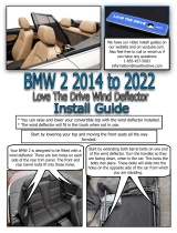
CAUTION: To avoid damage and to assist in the
removal of the headlining from the vehicle,
slightly flex the headlining as shown in the
illustration below.
8. Lower the headlining and disconnect the
electrical leads from the rear radio speakers,
remove the headlining from the vehicle.
Roof panel
9. Remove the screws (with washers) from
around the inner edge of the roof panel.
10. With assistance lift the roof panel from the
body,
remove
any
previous
sealing
compounds from around the edge of the roof
panel and body.
.
Open the hood and disconnect the battery
negative terminal.
Disconnect the under-hood lamp electrical
leads.
Disconnect the windscreen washer tube at the
‘T’
joint.
Release the four bolts securing the hood to
the hinges, note the ground strap located
under the upper left hand hood fixing, with
assistance lift the hood clear of the vehicle.
‘,
Cowl panel
Remove the wiper arms and two nuts securing
the wheel boxes to the cowl panel and
remove the two exterior sealing rubbers.
Remove the nine cross-head screws securing
the front of the cowl panel.
Remove the four bolts (with spring and plain
washers) retaining the cowl panel to the top
of the fenders, retrieve the nylon spacing
washers from between cowl panel and fender.
:
.’
14
,..,
.:.:

::’
‘.
..,.
,’
,
:
._
,’
R”o”v’;;
1987
CHASSIS AND BODY
RR2129E
8. Remove the four cross-head screws retaining
the panel to the
‘A’
post mounting brackets
located above the front door hinges.
9. With assistance place a tube over each of the
hinges and lower to enable the cowl panel to
be fed over the hinges, carefully return the
hinges to their upright position.
Front fender
10. Remove the two cross-head screws from the
top of the front side light assembly, maneuver
the assembly out of the two bottom location
holes.
11. Remove the bulb holder waterproof cover,
depress the two retaining clips and withdraw
the bulb holder from the rear of the lamp unit.
Remove the lamp unit.
12. Remove the two screws (with plain washers)
from the bottom of the side light recess.
13. Remove the three fixings securing the bumper
wrap around end cap and remove the
moulding from the bumper.
14.
Remove the bolt which secures the end of the
spoiler to the front of the wheel arch, located
forward of the road wheel at the bottom of
the fender.
15. Remove the five nuts and bolts (with plain and
spring washers) securing the top edge of the
fender to the wheel arch and valance
assembly.
16. Remove the two bolts (with plain washers)
securing the sill finishing strip to the bottom
of the fender.
17.
Remove the two cross-head screws securing
the fender to the mounting bracket attached
to the
‘A’
post located in between the front
door hinges.
Refitting
Front fender
18.
Apply a suitable underseal to the inner face of
the fender and a waterproof sealant to the
fender to wheel arch/valance mating faces.
19.
Ensure that before final tightening of the
fender securing bolts the fender aligns with
the edge of the front door.
20. Reverse remaining fender removal instructions.
Continued
.
REVISED: JULY 88
15

.‘.
:
.’
.>:
r:
..
.
.
,.’
,:/
i:,.
x
:
CHASSIS AND
BODY
1987
lWNGt
ROVER
Cowl panel
21.
22.
23.
24.
Lower the hinges to enable the cowl panel to
be fitted.
Fit the securing bolts ensuring that any nylon
spacers previously removed are refitted in their
original position.
Using a soft blunt implement ease the
windscreen rubber up onto the top of the
cowl panel.
Reverse the remaining cowl panel removal
instruction.
Hood
25.
26.
Fit the hood ensuring that before final
tightening of the
securing
bolts, the engine
ground strap is refitted to the forward bolt of
the left hand hinge, and that the hood aligns
with the cowl panel, fender and front grille,
adjust the hood at the hinges as necessary.
Reverse the remaining removal instructions.
ASSISTED HOOD
LIFT
Remove and refit
7.
Removing
8.
CAUTION: The assisted lift mechanism of the
hood eases the hood opening and lift procedure.
When the hood is fully open, secure the hood
stay in position. The assisted lift mechanism
alone WILL NOT retain the hood in its upright
position.
Carefully pry the wiper arms off the spindle
bosses, noting their position for re-assembly.
Raise the hood and disconnect the battery
negative terminal.
Disconnect the electrical lead to the hood
illumination lamp.
Disconnect the screen washer fluid feed pipe
at the
IT’
joint, remove the feed pipe from the
hood retaining clip.
NOTE: The removal of the hood will require the
assistance of a second person.
5. Release the four bolts (with plain washers)
9. Remove the nine cross-head screws from the
securing the hood to the hinges.
front of the cowl panel water channel.
NOTE: An engine ground strap is attached to the
forward bolt of the left hand hinge and must be
refitted when the hood is re-bolted to the
hinges.
6. With assistance lift the hood clear of the
hinges and store safely to one side, cover
hood to protect paintwork.
Remove the two wiper box wheel nuts and
rubber spacers.
Remove the four fixings securing the cowl
panel to the front fenders, the front two
fixings are accessible from the front of the
cowl panel, access to the rear two fixings is
gained by opening the front doors. Note the
nylon spacing washers at each bolt.
16
REVISED: JULY 88
‘..
.
:
:
.
i.
;:I..

PO;;;
1987
CHASSIS AND BODY
10. Place extension tubes over each hood hinge,
with assistance lower the
hinges,maneuver
the
cowl panel off the wiper arm shaft bosses and
along the tubes until the panel is clear of the
vehicle. Place the panel to one side and cover
to protect paintwork.
WARNING: Gradually let the torsion bar spring
tension return the hinges to their upright
position to prevent the possibility of personal
injury or damage to the vehicle.
11. Place an extension tube over the hinge, lower
the hinge until the stop bracket can be
removed, withdraw the bracket and gradually
allow the hinge to return to its upright
position.
15. Remove the two bolts (with plain washers)
securing the hinge to its mounting bracket.
16. Withdraw the hinge.
Refitting
17.
Fit the hinge and securely tighten the two
retaining bolts (with plain washers).
18. Fit the torsion bar ensuring that it is securely
located in the retaining clip and bracket.
I
9. Reverse the remaining removal instructions.
NOTE: Fit the ground strap under the forward
bolt of the left hand hinge.
20.
Using a soft blunt implement ease the bottom
lip of the windscreen seal up and over onto
the face
of
the cowl panel.
‘.
12.
:
13.
14.
Release the torsion bar from the retaining clip.
Maneuver the torsion bar until it can be
released from the hinge.
Release the torsion bar from the retaining
bracket.
17
,’
‘.

RANGE
CHASSIS AND BODY
“*’
ROVER
:
REAR CORNER PANEL AND FENDER
Remove and refit
CAUTION: IF A REPAIR IS BEING UNDERTAKEN
ON OR AROUND THE AREA OF THE REAR RIGHT
HAND FENDER AND HEAT IS TO BE APPLIED,
THE FENDER MUST BE REMOVED, AS A FUEL
EXPANSION TANK IS LOCATED BETWEEN THE
FENDER AND INNER BODY SIDE.
Removing
NOTE: Ensure the central locking system is
de-activated to enable the fuel filler flap to be
opened,
disconnect the battery negative
terminal.
I.
Open the fuel filler flap and remove the three
filler tube securing
screws.(Right
hand rear
fender only)
RR2130E
. .
2. Remove the rear stowage area parcel shelf and
spare wheel.
3. Remove the two nuts (with washers) securing
the bumper wrap around end cap to the
bottom of the corner panel.
4. Remove the single bolt securing the end cap
to the bumper, accessible from behind the
bumper.
5. Remove the fixings and release the rear tail
light cluster from the rear corner panel and
disconnect the electrical plug.
6. Drill out all the pop-rivets securing the corner
panel to the tailgate frame.
7. Remove the two nuts and bolts securing the
front of the fender to the
‘D’
post located
beneath the wheel arch.
8. Release the single nut and bolt retaining the
mud-flap bracket to the bottom of the fender.
9
From inside the
slowage
area remove the five
cross-head screws securing the top of the
fender to the
bodyside
panel. If necessary fold
the rear seat forward and remove the seat
locking mechanism housing to gain access to
the screw adjacent to the
ID’
post.
. .
10. Remove the rear fender and comer panel
complete.
11. Remove the seven bolts (with plain and spring
washers) securing the fender to the corner
panel and separate the two panels.
Refitting
12.
Assemble the corner panel to the rear fender,
fit the bolts and ensure both panels align
before final tightening.

.
.
.
>
,_..’
‘.
;
;“d”;;
1987
CHASSIS AND BODY
rid
13. Coat the underside of panels with a suitable
underseal.
14. Fit the assembly to the vehicle ensuring that
the door edge to fender edge and corner
panel to lower tailgate are in alignment before
the
fina;
tightening of screws and the fitting of
pop-rivets.
15. Reverse the remaining removal instructions.
FUEL FILLER FLAP
Remove and refit
Adjust
Removing
NOTE: The fuel filler flap is locked when the
vehicle
central locking system has been
activated,
ensure
the
system
has been
de-activated before attempting to open the flap.
I. Open the fuel filler flap.
2. Release the two screws (with plain washers).
3.
Withdraw the flap.
RR2073E
Refitting
4. Fit the flap, but do not fully tighten the screws
at this stage.
5. Close the flap and check that the outer profile
of the flap aligns with the rear fender, adjust
by easing the flap in or out of the opening.
6. Open the flap and securely tighten the screws.
REAR QUARTER PANEL-INTERIOR
Remove and refit
Removing
1.
2.
3.
4.
5.
NOTE: If removing the drivers side interior
or
exterior
quarter panel it will be
necessary to remove the spare wheel from
the rear stowage area.
Detach the plastic cover from the upper seat
belt guide bracket and remove the single bolt.
Remove the clip-on plastic cover from the seat
belt inertia reel. Remove the retaining bolt and
place the inertia reel to one side.
Release the two small cross-head screws
securing the trim panel to the body side.
Ease the front of the trim panel from behind
the quarter light glass rubber moulding.
Withdraw the panel from the vehicle.
Refitting
Ease the top front edge of the trim panel
(approximately the first
25mm,
1
inch) as close
to the headlining as is possible under the lip
of the rubber moulding.
Push the panel up behind the headlining until
the cross head screw holes line up with their
respective holes in the bodyside.
Using a soft blunt implement ease the rubber
moulding lip over the remainder of the front
of the trim panel.
Continued
19

CHASSIS AND BODY
1987
;;rv;r;
:.
::
:
.’
9. Ensuring that the electrical harness is located
in the channel at the rear of the trim panel fit
the two crosshead screws.
10. Ensuring that the seat belt is not twisted fit the
guide bracket and inertia reel, tighten the two
bolts to the specified torque (see section
06.Torque values).
71. Refit the plastic cover to the guide bracket.
REAR QUARTER PANEL-EXTERIOR
Remove and refit
Removing
NOTE: If removing the drivers side interior
or exterior quarter panel
it will be
necessary to remove the spare wheel from
the rear stowage area.
1. Remove the rear seat belt inertia reel and
guide bracket.
2. Remove the two crosshead screws and detach
the interior quarter panel.
3. Remove the three nuts (with plain washers)
securing the exterior quarter panel to the
bodyside. The nuts are accessible through the
large holes located adjacent to the rear quarter
light.
4. Remove the four screws securing the quarter
panel to the inside
edge of the tailgate
opening.
5.
Withdraw the panel.
:
Refitting
6. Reverse the removal instructions.
7. Ensure that the seat belts, inertia reel and
guide bracket bolts are tightened to the
specified
torque (see section
06-Torque
values).
:
,‘.
/