Broan DT4BF-KA/B Installation guide

Category
Heat pumps
Type
Installation guide

This manual is also suitable for

OUTDOOR SPLIT SYSTEM HEAT PUMP 16 SEER
TWO-STAGE, R-410A MODELS
IMPORTANT
ATTENTION INSTALLERS:
It is your responsibility to know this product better than your customer. This includes being able to install
the product according to strict safety guidelines and instructing the customer on how to operate and
maintain the equipment for the life of the product. Safety should always be the deciding factor when
installing this product and using common sense plays an important role as well. Pay attention to all safety
warnings and any other special notes highlighted in the manual. Improper installation of the furnace or
failure to follow safety warnings could result in serious injury, death, or property damage.
These instructions are primarily intended to assist qualified individuals experienced in the proper
installation of this appliance. Some local codes require licensed installation/service personnel for this
type of equipment. Please read all instructions carefully before starting the installation. Return these
instructions to the customer’s package for future reference.
DO NOT DESTROY. PLEASE READ CAREFULLY & KEEP IN A SAFE PLACE FOR FUTURE REFERENCE.
INSTALLATION INSTRUCTIONS
IMPORTANT SAFETY INFORMATION ............... 2
HEAT PUMP INSTALLATION .............................. 3
General Information ............................................ 3
Before You Install the Heat Pump ....................... 3
Locating the Heat Pump ..................................... 3
Packaging Removal ............................................ 3
Ground Level....................................................... 3
Rooftop ............................................................... 3
Connecting Refrigerant Tubing Between the Indoor &
Outdoor Unit ..................................................... 4
ELECTRICAL WIRING ......................................... 4
Pre-Electrical Checklist ....................................... 4
Line Voltage ........................................................ 4
Grounding ........................................................... 5
Thermostat / Low Voltage Connections .............. 5
CoreSense
TM
Diagnostics Module....................... 5
Compressor Protection ..................................... 5
Resetting Alert Codes ....................................... 6
Outdoor Fan Motor .............................................. 6
Optional Equipment ............................................ 6
Transformer Upgrade Kit ................................... 6
START UP & ADJUSTMENTS ............................ 7
Pre-Start Check List ............................................ 7
Start-Up Procedures ........................................... 7
Operating Temperatures ................................... 7
Air Circulation - Indoor Blower .......................... 7
System Cooling ................................................. 7
System Heating (Optional) ................................ 7
Short Cycle Protection ........................................ 7
Defrost Cycle Control .......................................... 7
Defrost Test Procedure ....................................... 8
Anti Short Cycle Timer Test ................................ 8
Heating Mode .................................................... 8
Cooling Mode .................................................... 8
REFRIGERANT CHARGING ............................... 8
Charging the Unit in AC Mode ............................ 9
Charging Charts & Application Notes ................. 9
Figure 4. Charging Chart for 2 Ton Units ........... 10
Figure 5. Charging Chart for 3 Ton Units ........... 10
Figure 6. Charging Chart for 4 Ton Units ........... 11
Figure 7. Charging Chart for 5 Ton Units ........... 11
Figure 8. Heat Mode Charging Chart ................ 12
WIRING DIAGRAMS ............................................ 13
Figure 9. W.D. for 2 Ton Models Without
CoreSense
TM ............................................................................................13
Figure 10. W.D. for 2 Ton Models With
CoreSense
TM ............................................................................................14
Figure 11. W.D. for 3 Ton Models Without
CoreSense
TM ............................................................................................15
Figure 12. W.D. for 3 Ton Models With
CoreSense
TM ............................................................................................16
Figure 13. W.D. for 4 & 5 Ton Models Without
CoreSense
TM ............................................................................................17
Figure 14. W.D. for 4 & 5 Ton Models With
CoreSense
TM ............................................................................................18
CORESENSE
TM
TROUBLESHOOTING ............... 19
Table 5. Coresense
TM
Diagnostics & LED
Troubleshooting ................................................. 19
HEAT PUMP MAINTENANCE ............................. 21
REPLACEMENT PARTS ...................................... 21
INSTALLATION CHECKLIST .............................. 24
2
IMPORTANT SAFETY INFORMATION
INSTALLER: Please read all instructions before servicing
this equipment. Pay attention to all safety warnings and
any other special notes highlighted in the manual. Safety
markings are used frequently throughout this manual to
designate a degree or level of seriousness and should
not be ignored.
WARNING indicates a potentially hazardous situation that
if not avoided, could result in personal injury or death.
CAUTION indicates a potentially hazardous situation that
if not avoided, may result in minor or moderate injury or
property damage.
WARNING:
ELECTRICAL SHOCK, FIRE OR
EXPLOSION HAZARD
Failure to follow safety warnings exactly could
result in serious injury or property damage.
Improper servicing could result in dangerous
operation, serious injury, death or property
damage.
 
to the equipment.
 
to disconnecting. Reconnect wires correctly.
 
WARNING:
This split system heat pump is shipped charged
with R410A refrigerant and ready for installation.
If repairs make it necessary for evacuation and
charging, it should only be attempted by qualified
trained personnel thoroughly familiar with this
equipment. Under no circumstances should
the owner attempt to install and/or service this
equipment. Failure to comply with this warning
could result in property damage, personal injury,
or death.
CAUTION:
This unit uses R-410A refrigerant. DO NOT use
any other refrigerant in this unit. Use of another
refrigerant will damage the unit.
WARNING:
Unless noted otherwise in these instructions,
only factory authorized parts or accessory
kits may be used with this product. Improper
installation, service, adjustment, or maintenance
may cause explosion, fire, electrical shock or
other hazardous conditions which may result in
personal injury or property damage.
Installation of equipment may require brazing
operations. Installer must comply with safety codes
and wear appropriate safety equipment (safety glasses,
work gloves, fire extinguisher, etc.) when performing
brazing operations.
• Followall precautionsintheliterature,ontags,and
on labels provided with the equipment. Read and
thoroughly understand the instructions provided with
the equipment prior to performing the installation and
operational checkout of the equipment.
• Usecautionwhenhandlingthisapplianceorremoving
components. Personal injury can occur from sharp
metal edges present in all sheet metal constructed
equipment.
WARNING:
The information listed below and the next page
must be followed during the installation, service,
and operation of this furnace. Failure to follow
safety recommendations could result in possible
damage to the equipment, serious personal
injury or death.
• The installer must comply with all local codes and
regulations which govern the installation of this type
of equipment. Local codes and regulations take
precedence over any recommendations contained in
these instructions. Consult local building codes and
the National Electrical Code (ANSI CI) for special
installation requirements.
• Allelectricalwiringmustbecompletedinaccordance
with local, state and national codes and regulations
and with the National Electric Code (ANSI/NFPA 70)
or in Canada the Canadian Electric Code Part 1 CSA
C.22.1.
• Thisequipmentcontainsliquidandgaseousrefrigerant
under high pressure. DO NOT USE ANY PORTION OF
THE CHARGE FOR PURGING OR LEAK TESTING.
Installation or servicing should only be performed by
qualified trained personnel thoroughly familiar with this
type equipment.
• Fullyannealed,refrigerantgradecoppertubingshould
be used when installing the system. Refrigerant suction
line tubing should be fully insulated.
• Thisunitisdesignedforoutdoorinstallationsonlyand
should be positioned as described on page 3.
3
HEAT PUMP INSTALLATION
General Information
Split system heat pumps are designed only for outdoor
rooftop or ground level installations. This unit has been
tested for capacity and efficiency in accordance with
AHRI Standards and will provide many years of safe
and dependable comfort, providing it is properly installed
and maintained. Abuse, improper use, and/or improper
maintenance can shorten the life of the appliance and
create unsafe hazards.
To achieve optimum performance and minimize equipment
failure, it is recommended that periodic maintenance be
performed on this unit. The ability to properly perform
maintenance on this equipment requires certain
mechanical skills and tools.
Before You Install the Heat Pump
The cooling load of the area to be conditioned must be
calculated and a system of the proper capacity selected.
It is recommended that the area to be conditioned be
completely insulated and vapor sealed.
Check the electrical supply and verify the power supply
is adequate for unit operation. The system must be wired
and provided with circuit protection in accordance with
local building codes. If there is any question concerning
the power supply, contact the local power company.
The indoor section (air handler, furnace, etc) should be
installed before routing the refrigerant tubing. Refer to
the indoor unit's installation instructions for installation
details.
All units are securely packed at the time of shipment and
upon arrival should be carefully inspected for damage
prior to installing the equipment at the job site. Verify
coil fins are straight. If necessary, comb fins to remove
flattened or bent fins. Claims for damage (apparent or
concealed) should be filed immediately with the carrier.
Please consult your dealer for maintenance information
and availability of maintenance contracts. Please read
all instructions before installing the unit.
Locating the Heat Pump
• Surveythejobsitetodeterminethebestlocationfor
mounting the outdoor unit.
• Overhead obstructions (Figure 1), poorly ventilated
areas, and areas subject to accumulation of debris
should be avoided.
• Sufcientclearanceforunobstructedairowthroughthe
outdoor coil must be maintained in order to achieve rated
performance. See Figure 1 for minimum clearances to
obstructions.
• Considerationshouldbegiventoavailabilityofelectric
power, service access, noise, and shade.
Packaging Removal
To prevent damage to the tubing onnections, carefully
remove the carton and user’s manual from the equipment.
Discard the shipping carton.
Ground Level
Ground level installations must be located according to
local building codes or ordinances and these requirements:
• Clearancesmustbeinaccordancewiththoseshown
in Figure 1.
• A suitable mounting pad must be provided and be
separate from the building foundation. The pad must
be level and strong enough to support the unit’s weight.
The slab height must be a minimum of 2” (5 cm) above
grade and with adequate drainage. See Figure 1.
Rooftop
• Themethodofmountingshouldbedesignedsothatit
does not overload roof structures or transmit noise to
the interior of the structure. The roof must be structurally
capable of handling the weight of the unit.
• Full perimeter support is required under the unit.
Support must be made of weather resistant materials
and installed prior to unit installation.
• Thesupportmustbebuilttoraisetheunit6"abovethe
roof.
6"
24" for
Service Access
12" See
Note
12"
See Note
DO NOT
OBSTRUCT
TOP OF UNIT
NOTE: Units require full perimeter clearances. Installer must maintain
18” between two units or 12” between single unit and structure.
Building or Structure
2”
48”
Figure 1. Clearance Requirements
4
Connecting Refrigerant Tubing Between
the Indoor & Outdoor Unit
CAUTION:
When servicing, cover or seal openings to
minimize the exposure of the refrigerant system
to air to prevent accumulation of moisture and
other contaminants.
After outdoor and indoor unit placement has been
determined, route refrigerant tubing between the
equipment in accordance with sound installation practices.
• When connecting refrigerant linesets together, it is
recommended that dry nitrogen be flowing through the
joints during brazing. This will prevent internal oxidation
and scaling from occurring.
• Refrigeranttubingshouldberoutedinamannerthat
minimizes the length of tubing and the number of bends
in the tubing.
• Refrigeranttubingshouldbesupportedinamanner
that the tubing will not vibrate or abrade during system
operation.
• Tubingshouldbekeptcleanofforeigndebrisduring
installation.
• Everyeffortshouldbemadebytheinstallertoensure
that the field installed refrigerant containing components
of the system have been installed in accordance with
these instructions and sound installation practices to
insure reliable system operation and longevity.
The maximum recommended interconnecting
refrigerant line length is 75 feet, and the vertical elevation
difference between the indoor and outdoor sections
should not exceed 20 feet.
• If precise forming of refrigerant lines is required, a
copper tubing bender is recommended. Avoid sharp
bends and contact of the refrigerant lines with metal
surfaces.
• A lter dryer is provided with the unit and must be
installed in the liquid line of the system. If the installation
replaces a system with a filter dryer already present
in the liquid line, the filter dryer must be replaced with
ELECTRICAL WIRING
WARNING:
To avoid risk of electrical shock, personal
injury, or death, disconnect all electrical power
to the unit before performing any maintenance
or service. The unit may have more than one
electrical supply.
Label all wires prior to disconnection when
servicing the unit. Wiring errors can cause
improper and dangerous operation
• Allelectricalconnectionsmustbeincompliancewith
all applicable local codes and ordinances, and with the
current revision of the National Electric Code (ANSI/
NFPA 70).
• ForCanadianinstallationstheelectricalconnections
and grounding shall comply with the current Canadian
Electrical Code (CSA C22.1 and/or local codes).
Pre-Electrical Checklist
Verify that the voltage, frequency, and phase of the
supply source match the specifications on the unit
rating plate.
Verify that the service provided by the utility is sufficient
to handle the additional load imposed by this equipment.
Refer to the unit wiring label for proper high and low
voltage wiring.
Verify factory wiring is in accordance with the units
wiring diagram. See Figure 9, (page 13), Figure 10,
(page 14), Figure 11, (page 15), Figure 12, (page
16), Figure 13, (page 17), & Figure 14, (page 18).
Inspect for loose connections.

• Awiringdiagramislocatedontheinsidecoverofthe
electrical box of the outdoor unit. The installer should
become familiar with the wiring diagram before making
any electrical connections to the outdoor unit.
• An electrical disconnect must be located within
sight of and readily accessible to the unit. This
switch shall be capable of electrically de-energizing
the outdoor unit.
• Line voltage to the unit should be supplied from a
dedicated branch circuit containing the correct fuse
or circuit breaker for the unit. Incoming field wiring
and minimum size of electrical conductors and circuit
protection must be in compliance with information listed
on the outdoor unit data label. Any other wiring methods
must be acceptable to authority having jurisdiction.
Table 1. Copper Wire Size
COPPER WIRE SIZE — AWG

SUPPLY WIRE LENGTH-FEET
SUPPLY CIRCUIT
AMPACITY
200 150 100 50
6 8 10 14 15
4 6 8 12 20
4 6 8 10 25
4 4 6 10 30
3 4 6 8 35
3 4 6 8 40
2 3 4 6 45
2 3 4 6 50
2 3 4 6 55
1 2 3 4 60
Wire Size based on N.E.C. for 60° type copper conductors.
the one supplied with the unit. The filter dryer must be
installed in strict accordance with the manufacturer’s
installation instructions.
• Optionalequipmentsuchasliquidlinesolenoidvalves,
low ambient, etc., should be installed in strict accordance
with the manufacturer’s installation instructions.
5
Figure 2. Typical 2 - Stage Heat Pump w/ Optional

GRW2 CEOY1
Thermostat
OD
Stat
O
Y1
R
C
Air Handler
Heat Pump OD
Section
W
2
E
W2
W1
O
Y/Y2
G
R
C
Y2
Y2
W1
W3
Y1
NOTE: Jumper
W1 & W2 together
for shorter staging
time.
• Theoutdoorunitrequiresbothpowerandcontrolcircuit
electrical connections. Refer to the wiring diagrams for
identification and location of outdoor unit field wiring
interfaces. Make all electrical connections in accordance
with all applicable codes and ordinances.
• Overcurrentprotectionmustbeprovidedatthebranch
circuit distribution panel and sized as shown on the unit
rating label and according to applicable local codes.
See the unit rating plate for minimum circuit ampacity
and maximum overcurrent protection limits.
• Providepowersupplyfortheunitinaccordancewiththe
unit wiring diagram, and the unit rating plate. Connect
the line-voltage leads to the terminals on the contactor
inside the control compartment.
• Useonlycopperwireforthelinevoltagepowersupply
to this unit as listed in Table 1, (page 4). Use proper
code agency listed conduit and a conduit connector
for connecting the supply wires to the unit. Use of rain
tight conduit is recommended.
• 208/230Voltunitsareshippedfromthefactorywired
for 230 volt operation. For 208V operation, remove the
lead from the transformer terminal marked 240V and
connect it to the terminal marked 208V.
• Optionalequipmentrequiringconnectiontothepower
or control circuits must be wired in strict accordance
of the NEC (ANSI/NFPA 70), applicable local codes,
and the instructions provided with the equipment.
Table 2. Thermostat Wire Gauge
THERMOSTAT
WIRE GAUGE
MAXIMUM RECOMMENDED

24 25
22 45
20 70
18 110
Grounding
WARNING:
The unit cabinet must have an uninterrupted or
unbroken electrical ground to minimize personal
injury if an electrical fault should occur. Do not
use gas piping as an electrical ground!
This unit must be electrically grounded in accordance
with local codes or, in the absence of local codes, with
the National Electrical Code (ANSI/NFPA 70) or the CSA
C22.1 Electrical Code. Use the grounding lug provided in
the control box for grounding the unit.

• Thermostatconnectionsshouldbemadeinaccordance
with the instructions supplied with the thermostat and
the indoor equipment. A typical installation with a heat
pump thermostat and air handler is shown in Figure 2.
• Theoutdoorunitisdesignedtooperatefroma24VAC
Class II control circuit. The control circuit wiring must
comply with the current provisions of the NEC (ANSI/
NFPA 70) and with applicable local codes having
jurisdiction.
• Thelowvoltagewiresmustbeproperlyconnectedto
the units low voltage terminal block. Recommended
wire gauge and wire lengths for typical thermostat
connections are listed in Table 2.
• The thermostat should be mounted about 5 feet
above the floor on an inside wall. DO NOT install the
thermostat on an outside wall or any other location
where its operation may be adversely affected by radiant
heat from fireplaces, sunlight, or lighting fixtures, and
convective heat from warm air registers or electrical
appliances. Refer to the thermostat manufacturer’s
instruction sheet for detailed mounting and installation
information.
CoreSense
TM
Diagnostics Module

The CoreSense
TM
Diagnostics Module (Figure 2) is a
breakthrough innovation for troubleshooting heat pump and
air conditioning system failures. The module installs easily
in the electrical box of the outdoor unit near the compressor
contactor.By using the compressor as a sensor, CoreSense
Diagnostics helps the service technician more accurately
troubleshoot system and compressor fault conditions.
A flashing LED indicator communicates the ALERT code
and a diagnostic key is also imprinted on the side of the
module to quickly direct the technician to the root cause
of a problem. Alert identification codes are also listed in
Table 5, (page 19).
Compressor Protection
The CoreSense
TM
Diagnostics module utilizes proprietary
algorithms to protect the compressor and system from
repeated trips of system pressure controls and the
compressor internal overload. The protection terminal
of the module should be wired in series with the system
low pressure and high pressure cutouts, as well as the
compressor contactor. When the module detects a series
6
of trips as described below, it will activate a lockout feature
that opens the normally closed protection contacts in
the module, thereby cutting power to the contactor and
shutting off the compressor.
Resetting Alert Codes
When the CoreSense
TM
Diagnostics module has detected a
series of adverse conditions that have caused it to lockout
the compressor, and after the issue has been resolved,
it is necessary to manually reset the module in order to
clear the present alert code.
The primary way of clearing the code and resetting the
alert is to press the reset button located on the module.
NOTE: Pressing the reset will require a pin or a mini
electronics screwdriver. This button must be pressed and
held for a minimum of one second for the module to be
reset. Pressing the reset button clears the immediate lock
code and the seven day operating history. It will not clear
the permanent module history. In the case of the three-
wire module, the codes can be reset or cleared by cycling
power to the module. This can be done by disengaging
the Common (C) terminal. This will not clear the seven
day operating history.
Outdoor Fan Motor
If the unit utilizes a 2-speed condenser fan motor, this
motor will operate on low speed when in low cooling,
and on high speed when in high cooling. A relay within
the control area switches the fan motor from low to high
speed using the call for high cooling as the trigger. Other
models that utilize BLDC fixed torque variable speed fan
motors will not require a relay.
Optional Equipment
Optional equipment requiring connection to the power
or control circuits must be wired in strict accordance
with current provisions of the NEC (ANSI/NFPA 70),
with applicable local codes having jurisdiction, and the
installation instructions provided with the equipment.
Optional Equipment (low ambient control, hard start
kits, etc.) should be installed in strict accordance with
the manufacturer’s installation instructions. A functional
checkout should be performed in accordance with the
checkout procedures supplied with the equipment.
Transformer Upgrade Kit
If this 2-stage heat pump is installed in conjunction with
a gas furnace and fossil fuel kit, the furnace transformer
MUST be upgraded to one with a 60 VA rating or using
the transformer upgrade kit (904077). To upgrade the
transformer:
• Removetheexistingtransformerandinstallthenew
60 VA transformer.
• Removethe3ampfuseonthefurnacecontrolboard
and install the 5 amp fuse provided.
NOTE: The new transformer may be larger than the
existing transformer that is mounted in the furnace. If this
happens, mount the 60 VA transformer using one of the
mounting holes in the furnace panel. On the other side
either drill a 0.149 hole in the panel and use the existing
fastener, or use a self-drilling fastener to secure the other
side of the transformer.
Figure 3. CoreSense
TM
Diagnostics Module
Y2 (Thermostat 2nd Stage Demand)
Y (Thermostat Demand)
Data Port
L (Alert)
R (24VAC)
Prot (Contactor Cutout)
DC SOL (2nd Stage Solenoid Power)
C (Common)
Power LED
Alert LED (Yellow)
Tr ip / Lock LED (Red)
7
4. Allow the system to operate for several minutes and then
set the temperature selector above room temperature.
Verify the fan and compressor cycle off with the
thermostat. NOTE: The blower should also stop unless
fan switch is set to the ON position.
System Heating (Optional)
1. If heating equipment (furnace, air handler) is provided
with the system, lower the thermostat setpoint
temperature to the lowest temperature setting and
change the thermostat’s system mode to HEAT.
2. Gradually increase the thermostat’s setpoint
temperature to the maximum setting.
3. Verify the optional heating equipment (furnace or
electric heat) and indoor blower energize. Feel the air
being circulated by the indoor blower and verify that
it is warmer than ambient temperature. Listen for any
unusual noises. If unusual sounds occur, determine the
source of the noise and correct as necessary.
NOTE: Other sources for heating (electric furnace, fossil
fuel furnace, air handler with electric heat options, etc.)
that interface with the heat pump should be functionally
checked to verify system operation and compatibility
with the heat pump. Refer to the installation instructions
for this equipment and perform a functional checkout in
accordance with the manufacturer’s instructions.
Short Cycle Protection
1. With the system operating in COOLING mode, record
the setpoint temperature setting of the thermostat.
2. Gradually raise the setpoint temperature until the outdoor
unit and indoor blower de-energize.
3. Immediately lower the setpoint temperature of the
thermostat to its original setting and verify that the
indoor blower is energized and that the outdoor unit
remains de-energized.
4. After approximately 3 minutes, verify that the outdoor
unit energizes and the temperature of the air supplied
to the facility is cooler than ambient temperature.
Defrost Cycle Control
The defrost cycle is controlled by an Adaptive Demand
Defrost algorithm that monitors coil temperature and
ambient temperature. Other features of the of the demand
defrost board include:
• 4 Field selectable defrost termination temperatures
(50° F - 80° F coil temperature).
• Fieldselectablecompressordelayfeature.
• Highpressureandlowpressureswitches.
• Sensingofsecondstagecompressordemand.
• Test/speedupcapability.
• Anti short cycle timer (3 minutes) for compressor
protection.
• On board diagnostics with ashing LED for quicker
troubleshooting. See Table 4, (page 8).
START UP & ADJUSTMENTS
Pre-Start Check List
Verify the unit is level and has sufficient clearances for
unobstructed airflow.
Verify the outdoor coil and top of the unit are free from
obstructions and debris, and all equipment access/
control panels are in place.
Verify that the line voltage power leads are securely
connected and the unit is properly grounded.
Verify that the low voltage wires are securely connected
to the correct leads on the low voltage terminal strip.
Verify that the power supply branch circuit overcurrent
protection is sized properly.
Verify that the thermostat is wired correctly.
Start-Up Procedures
WARNING:
This unit is equipped with a crankcase heater.
Allow 24 hours prior to continuing the start up
procedures to allow for heating of the refrigerant
compressor crankcase. Failure to comply may
result in damage and could cause premature
failure of the system. This warning should be
followed at initial start up and any time the power
has been removed for 12 hours or longer.
Operating Temperatures
This equipment has been designed to operate within the
temperatures specified inTable 3. Running the equipment
in heating at higher than 70° F may require the use of a
Heat Pump Mild Weather Control Kit or changing over to
emergency or auxiliary heating.
Air Circulation - Indoor Blower
1. Set the thermostat system mode on OFF and the fan
mode to ON.
2. Verify the blower runs continuously. Check the air delivery
at the supply registers and adjust register openings for
balanced air distribution. If insufficient air is detected,
examine ductwork for leaks or obstructions.
3. Set the thermostat fan mode to AUTO and verify the
blower stops running.
System Cooling
1. Set the thermostat’s system mode to COOL and the
fan mode to AUTO. Gradually lower the thermostat
temperature setpoint below room temperature and
verify the outdoor unit and indoor blower energize.
2. Verify blower wheel is spinning in direction indicated by
arrow. Feel the air being circulated by the indoor blower
and verify that it is cooler than ambient temperature.
Listen for any unusual noises. If unusual sounds occur,
determine the source of the noise and correct as
necessary.
3. Verify HI and LO refrigerant pressures.
NOTE: If refrigerant pressures are abnormal and the
compressor is rotating backwards, shut off main power to
the unit and switch any two field wires at the disconnect.
DO NOT alter unit wiring.
Table 3. Heat Pump Operating Temperatures
COOLING HEATING
MIN (°F) MAX (°F) MIN (°F) MAX (°F)
60 115 -10 70
8
Control is uncalibrated when power is applied. Calibration
occurs after a defrost cycle. The control initiates this
sacrificial defrost after 34 minutes of accumulated
compressor run time in heating with coil temperature
below 35° F. The defrost cycle terminates if coil sensor
reaches selected termination temperature or after 14
minutes defrost.
Defrost function is disabled if coil temperature is above
35° F. If Ambient sensor is detected as open or shorted,
demand defrost will not operate and control will revert
to time/temperature defrost operation. If the outdoor coil
sensor is detected as open or shorted, the control will not
perform demand or time/temperature defrost operation.
NOTE: When the defrost cycle initiates, there will be a
30 second compressor delay going into and out of the
defrost cycle. This delay may be removed by removing
P6 connector on the board.
This 2-stage unit will defrost in second stage regardless
of the stage called for by the thermostat.
NOTE: All units are shipped from the factory with the
default termination temperature set at 70° F.
Defrost Test Procedure
1. Terminals R - C must have 18-30VAC present between
them in order for defrost sequences to be initiated.
2 With heat mode thermostat demand (Y connected to
R), short and hold the TEST pins together. This will
energize reversing valve to initiate a forced defrost.
NOTE: This will bypass the ASCD and allow the high
stage compressor to come on immediately (if the
REMOVE FOR NO DELAY jumper at P6 is removed). If
the REMOVE FOR NO DELAY jumper at P6 is installed,
the compressor will energize immediately following a
30-second delay.
3. Remove the short on the TEST pins.
• If the Coil temperature is above the Terminate
Temperature selection setting, the defrost cycle will
be terminated (reversing valve will de-energized).
• If the coil temperature is below the Terminate
Temperature election setting, the defrost cycle will
continue for 14 minutes or until the coil temperature
rises above the Terminate Temperature selection
setting. NOTE: Short the TEST pins for 1 second
or more to force the control out of defrost and back
to heating mode (reversing valve de-energized).
Compressor will turn on immediately (if the REMOVE
FOR NO DELAY jumper is removed).
• IftheREMOVEFORNODELAYjumperisinstalled,
the compressor will energize immediately following
a 30-second delay.
NOTE: If the Y2 thermostat input is energized (2 - stage
system), the second stage will turn on. If the steps above
do not initiate a defrost, replace the defrost board.
Anti Short Cycle Timer Test
The 3-minute time delay feature can be bypassed by
shorting the TEST pins together.
Heating Mode
When the TEST pins are shorted together for more than
1-second, the control will switch between defrost mode
and heating mode (as described in the Defrost Test
Procedure section).
Cooling Mode
When the TEST pins are shorted together for more than
1-second, the Anti Short Cycle Timer will be bypassed.
REFRIGERANT CHARGING
WARNING:
This split system heat pump is shipped charged
with R410A refrigerant and ready for installation.
If repairs make it necessary for evacuation and
charging, it should only be attempted by qualified
trained personnel thoroughly familiar with this
equipment. Under no circumstances should
the owner attempt to install and/or service this
equipment. Failure to comply with this warning
could result in property damage, personal injury,
or death.
After refrigerant line connections are completed, it is
required that you leak check and evacuate the indoor
section and all line connections (using proper methods)
before finalizing the full system refrigerant charge.
• Toachieveratedcapacityandefciency,thecompressor
must be exposed to refrigerant for at least 24 hours
prior to running and then the compressor must be run
for a minimum of 12 hours.
• Therefrigerantchargecanbecheckedandadjusted
through the service ports provided external to the
outdoor unit. Use only gage line sets which have a
“Schrader” depression device present to actuate the
valve. A common suction port for heating mode charging
is included and located on the compressor access panel
above the outdoor unit service valves.
• Figure 8, (page 12) is provided for quick reference
when the unit is in heating mode and for the inspection
of the liquid line pressures and temperatures.
• A high-pressure switch is factory installed and located
internally on the compressor discharge line of the
outdoor unit. If the discharge pressure rises above 650
psig, the switch will open and de-energize the outdoor
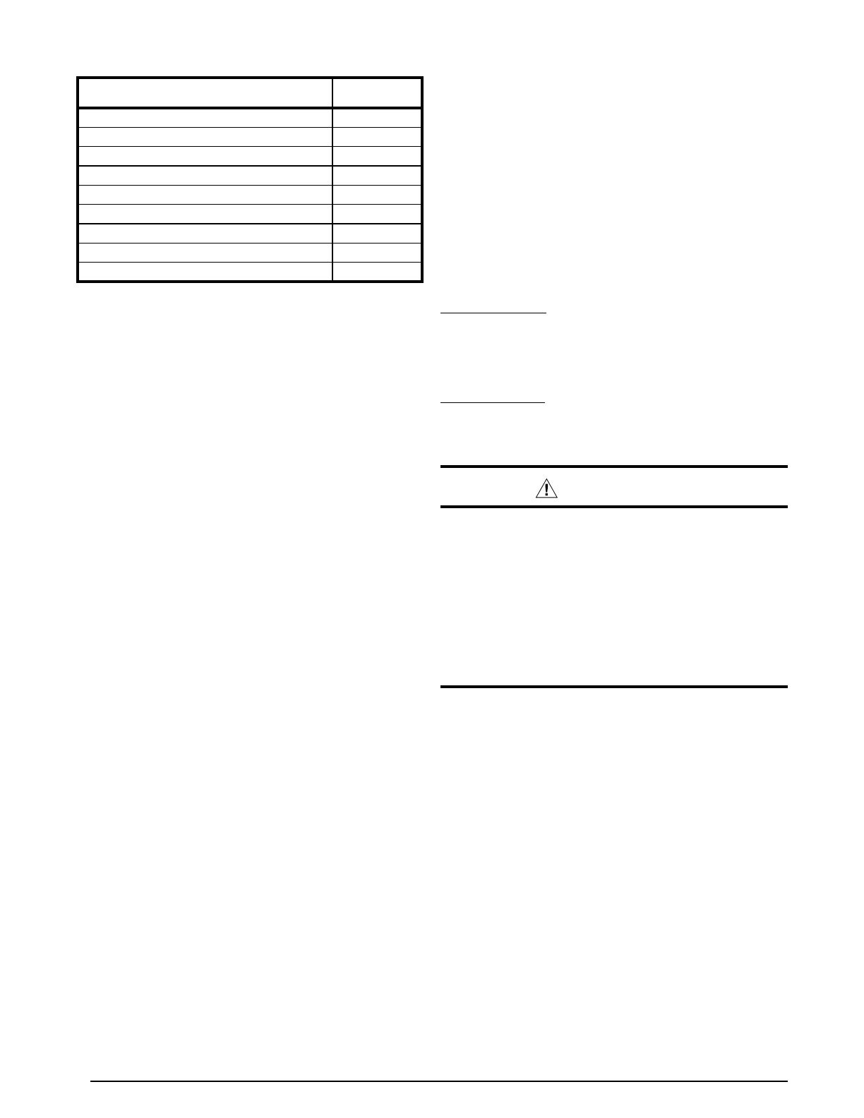
DIAGNOSTIC DESCRIPTION
LED
STATUS
Control Fault (No Power) Off
Normal Operation On
ASCD Delay Active (with compressor demand) 1 Flash
Low Pressure Switch Lockout 2 Flashes
High Pressure Switch Lockout 3 Flashes
Ambient Sensor Fault 4 Flashes
Coil Sensor Fault 5 Flashes
Low Pressure Switch Open 6 Flashes
High Pressure Switch Open 7 Flashes
Table 4. Control Diagnostic
9
Charging Charts & Application Notes
• This equipment’s cooling system contains
refrigerant under high pressure. Always use safe
and environmentally sound methods when handling
refrigerant handling or servicing the unit. Review
the factory literature and safety warnings prior to
servicing.
• Cooling mode charging charts are applicable only
to matched assemblies of this equipment and listed
airflows for the indoor coil. Outdoor units with non-
AHRI lsited indoor coils are not recommended and
deviations from rated airflows or non-listed combinations
may require modification to the expansion device and
refrigerant charging procedures for proper and efficient
system operation. Refer to Figure 4, (page 10), Figure
5, (page 10), Figure 6, (page 11) & Figure 7, (page
11) for correct system charging.
• Whenrepairingsystemleaks,alwaysuseanitrogen
(inert) gas to protect the refrigerant system and pressure
check the repair before re-charging. Always replace
the filter-dryers when performing any repair to the
refrigeration system with one capable of acid removal.
After completing the repairs, evacuate the system to
350 - 500 microns and weigh in the refrigerant to the
amount specified on the unit rating label.
• Chargingchartsarevalidforavarietyofindoor,return
air conditions and are most influenced by the outdoor
ambient temperature, outdoor fan operation and the
unit operating voltage. Before using these charts, make
sure the unit is in a stable operating mode.
• AsshowninFigure 4, Figure 5, Figure 6 & Figure 7 the
ideal system sub-cooling can vary over the range of
operation. Reference the charts to determine the ideal
amount of sub-cooling for a given liquid pressure. Units
charged to other values will not perform at the rated unit
efficiency (EER) or rated Coefficient of Performance
(COP) in heating mode.
To inspect a systems operation using quality
instruments, match the measured liquid temperature to
the units chart. The measured liquid pressure reading
should be within 3% of the charts value for most
installations.
• Forsystemsthatareoperatingwithmorethana5%
deviation, inspect the unit for the proper voltage and
phase balance and the refrigeration system for leaks.
• Unitsthatareoperatingatlessthen95%ofthenominal
voltage or with a 2% phase imbalance may see a more
significant deviation than the amount stated above.
• DO NOT use the charts in systems that have a fan cycling
under low-ambient control. Refer to the low-ambient kit
instructions for more information. (If applicable)
unit. The switch will close again after the discharge
pressure decreases to 460 psig. NOTE: When the
switch opens and then closes, there will be a 3 minute
short cycling delay before the outdoor unit will energize.
Under normal conditions the switch is closed
• A low-pressure switch is factory installed and located
internally on the suction line of the outdoor unit. The
switch is designed to protect the compressor from a
loss of charge by interrupting the thermostat inputs to
the unit.
• Ifthesuctionpressurefallsbelow5psig,theswitchwill
open and de-energize the outdoor unit. The switch will
close again when the suction pressure increases above
20 psig. When the switch opens and then closes, there
is a 3 minute short cycling delay before the outdoor
unit will energize. Under normal conditions the switch
is closed.
To properly charge these units:
1. Read all Installation Instructions first.
2. Complete any brazing operations. (e.g. Split system
line-sets)
3. Leak check and evacuate the whole system using proper
methods.
4. Purge the nitrogen holding charge.
5. Evacuate the unit to 350-500 microns.
6. Allow the unit to remain under vacuum for at least 30
min.
7. Weigh-In the proper amount of new (or reclaimed)
R-410A refrigerant. Refer to the units Quick Reference
Data Sheet to determine the correct amount of charge.
Charging the Unit in AC Mode
(At outdoor temperatures above 65° F)
1. With the system operating at steady-state, measure the
liquid refrigerant pressure (in psig) at the outdoor unit
service valve.
2. Measure the liquid refrigerant temperature (in
Fahrenheit) at the service valve.
3. Determine the required liquid refrigerant pressure. See
Figure 3, Figure 4, Figure 5, & Figure 6.
• IfthepressuremeasuredinStep1isgreaterthan
the required liquid refrigerant pressure determined in
Step 3, then there is too much charge in the system.
Remove refrigerant and repeat Steps 1 through 3
until the system is correctly charged.
• IfthepressuremeasuredinStep1islessthanthe
required liquid refrigerant pressure determined in
Step 3, there is too little charge in the system. Add
refrigerant and repeat Steps 1 through 3 until the
system is correctly charged.
10
Figure 4. Charging Chart for 2 Ton Units
250
275
300
325
350
375
400
425
450
475
70 75 80 85 90 95 100105 110 115 120 125
Liquid Temperature (° F)
Liquid Pressure (psig)
Remove refrigerant when above curve
Add refrigerant when below curve
Figure 5. Charging Chart for 3 Ton Units
Liquid Temperature (° F)
Liquid Pressure (psig)
250
275
300
325
350
375
400
425
450
475
500
70 75 80 85 90 95 100 105110 115 120 125
Remove refrigerant when above curve
Add refrigerant when below curve
11
Figure 6. Charging Chart for 4 Ton Units
Liquid Temperature (° F)
Liquid Pressure (psig)
250
275
300
325
350
375
400
425
450
475
500
70 75 80 85 90 95 100 105 110 115120 125
Remove refrigerant when above curve
Add refrigerant when below curve
Figure 7. Charging Chart for 5 Ton Units
Liquid Temperature (° F)
Liquid Pressure (psig)
250
275
300
325
350
375
400
425
450
475
500
70 75 80 85 90 95 100 105 110 115120 125
Remove refrigerant when above curve
Add refrigerant when below curve
12
Figure 8. Heat Mode Charging Chart
Liquid Temperature (° F)
Liquid Pressure (psig)
200
225
250
275
300
325
350
375
400
50 55 60 65 70 75 80 85 90
Remove refrigerant when above curve
Add refrigerant when below curve
13
WIRING DIAGRAMS
HPS
W2 OUT
LPS
Y
OUT
Y2
OUT
Y2
W2 IN
L
COIL
C
Y
O
R
AMBDF1DF2
RV
OUTDOOR
FAN MOTOR
T1 T2
L1
L2
RIGHT
COMPRESSOR
HPS
LPS
RV COIL
C
R
S
CCH
BLACK
YELLOW
RED
C
H
C
TO THERMOSTAT
AMB SENSOR
OD SENSOR
CAPACITOR
CONTACTOR
LEFT
DEFROST BOARD
C
GRND L1 L2
SINGLE PHASE
FIELD SUPPLY
GROUNDING
SCREW
F
BLACK
ORANGE
S
R
BLUE
C
S
R
H
C
F
208/230V .zH 06 / esahP egniSrotoM naF CSP dna tsorfeD dnameD htiW )noitceS roodtuO( pmuP taeH metsyS tilpS egatS owT
WIRING DIAGRAM
NOTES:
1. Disconnect all power before servicing.
2. For supply connections use copper conductors only.
3. Not suitable on systems that exceed 150 volts to ground.
4. For replacement wires use conductors suitable for 105 deg C.
5. For ampacities and overcurrent protection, see unit rating plate.
6. Connect to 24 vac/40va/class 2 circuit. See furnace/air handler
installation instructions for control circuit and optional
relay/transformer kits.
1. Couper le courant avant de faire letretien.
2. Employez uniquement des conducteurs en cuivre.
3. Ne convient pas aux installations de plus de 150 volt a la terre.
711120A
0713
FIELD WIRING
LEGEND:
LOW VOLTAGE
HIGH VOLTAGE
BLACK
BLACK
YELLOW
YELLOW
YELLOW
BLACK
HPS
W2 OUT
LPS
Y
OUT
Y2
OUT
Y2
W2
IN
L
COIL
C
Y
O
R
AMBDF1DF2
RV
DEFROST BOARD
RV COIL
LPS
HPS
R
S
C
CCH
L2
L1
T2
T1
OUTDOOR
FAN MOTOR
COMPRESSOR
CAPACITOR
CC
Y
R
O
C
W2
Y2
L
CSC
AMB
SENSOR
COIL
SENSOR
208/230V
CC- Contactor Coil
CCH - Crankcase Heater
CSC - Compressor Solenoid Coil
LPS - Low Pressure Switch
HPS - High Pressure Switch
RVS - Reversing Valve Solenoid
Figure 9. W.D. for 2 Ton Models Without CoreSense
TM
14
HPS
W2 OUT
LPS
Y
OUT
Y2
OUT
Y2
W2 IN
L
COIL
C
Y
O
R
AMBDF1 DF2
RV
OUTDOOR
FAN MOTOR
Y2
Y
L
R
C
P
DC SOL
CORESENSE
MODULE
COMPRESSOR
HPS
LPS
RV COIL
CCH
TO THERMOSTAT
AMB SENSOR
OD SENSOR
CONTACTOR
T1 T2
L1 L2
LEFT
RIGHT
DEFROST BOARD
RED
BLACK
YELLOW
GRND
GROUNDING
SCREW
L1
L2
ROUTE THIS WIRE
THROUGH THE “R”
OPENING IN
CORESENSE MODULE
ROUTE THIS WIRE
THROUGH THE “C”
OPENING IN
CORESENSE
MODULE
ROUTE THIS WIRE
THROUGH THE “S”
OPENING IN
CORESENSE
MODULE
C
R
S
C
CAPACITOR
SINGLE PHASE FIELD SUPPLY
C
R
S
H
C
F
BLACK
ORANGE
BLUE
BLACK
YELLOW
YELLOW
GRAY
BLUE
YELLOW
BLACK
RED
BROWN
H
C
F
HPS
W2 OUT
LPS
Y
OUT
Y2
OUT
Y2
W2
IN
L
COIL
C
Y
O
R
AMBDF1 DF2
RV
DEFROST BOARD
RV COIL
LPS
HPS
CCH
L2
L1
T2
T1
OUTDOOR
FAN MOTOR
COMPRESSOR
CAPACITOR
CORESENSE
Y
R
O
C
W1
Y2
L
CC
Y2
Y
LR
CP
DC
SOL
CSC
AMB
SENSOR
COIL
SENSOR
208/230V
208/230V
Two Stage Split System Heat Pump (Outdoor Section) With Demand Defrost and PSC Fan Motor Single Phase / 60 Hz.
1. Disconnect all power before servicing.
2. For supply connections use copper conductors only.
3. Not suitable on systems that exceed 150 volts to ground.
4. For replacement wires use conductors suitable for 105
5. For ampacities and overcurrent protection, see unit rating plate.
6. Connect to 24 vac/40va/class 2 circuit. See furnace/airhandler installation
instructions for control circuit and optional relay/transformer kits.
1. Couper le courant avant
de faire letretien.
2. Employez uniquement des
conducteurs en cuivre.
3. Ne convient pas aux installations
de plus de 150 volt a la terre.
°C
NOTES:
CC- Contactor Coil
CCH - Crankcase Heater
CSC - Compressor Solenoid Coil
LPS - Low Pressure Switch
HPS - High Pressure Switch
RVS - Reversing Valve Solenoid
BLACK
WHITE
BLUE
ORANGE
BROWN
YELLOW
RED
R
S
C
C
R
S
WIRING DIAGRAM
FIELD WIRING
LEGEND:
LOW VOLTAGE
HIGH VOLTAGE
Normal Operation, no trip
Status LED
Normal Run; Solid Green
N/A N/A
N/A
N/A
N/A
N/A
N/A
4 cons, 10x total
4 cons, 10x total
4 cons, 10x total
1 Occurrence
1 Occurrence
1 Occurrence
10 consecutive
Red: Flash 2
Red: Flash 3
Red: Flash 4
Red: Flash 5
Red: Flash 6
Red: Flash 7
Red: Flash 10
N/A
Code 1; Yellow Flash 1
Code 2; Yellow Flash 2
Code 3; Yellow Flash 3
Code 4; Yellow Flash 4
Long Run Time. Compressor running extremely long run cycle. (disabled in HP mode.)
CoreSense LED DESCRIPTION Lockout Level Lockout Indication
Comprsesor Pressure Trip. Disch. or suct. pressure out of limits or compressor overloaded.
Short Cycling. Compressor is running only briefly.
Locked Rotor.
Code 5; Yellow Flash 5 Compressor Moderate Run. Compressor runs >15min, then trips >7min.
Code 6; Red Flash 6 Open Start Circuit. Current only in run circuit.
Code 7; Red Flash 7 Open Start Circuit. Current only in start circuit.
Code 8; Yellow Flash 8 Welded Contactor. Compressor always runs.
Code 9; Yellow Flash 9 Low Voltage. Control circuit <17 VAC.
Code 10; Red Flash 10 Over Current Protection. PROT terminal has >2A input for more than 40ms
TM
711212A
(Replaces 7112120)
0315
Figure 10. W.D. for 2 Ton Models With CoreSense
TM
15
AMB
HPS
W2 OUT
LPS
Y
OUT
Y2
OUT
Y2
W2 IN
L
COIL
C
Y
O
R
DF1 DF2
RV
BLACK
RED
OUTDOOR
FAN MOTOR
T1 T2
L1 L2
COMPRESSOR
HPS
LPS
RV COIL
CCH
BLACK
RED
BLUE
ORANGE
H
F
C
R
S
TO THERMOSTAT
AMB SENSOR
OD SENSOR
CONTACTOR
DEFROST BOARD
LFT
RT
S
L
H
C
NC
NO
COM
GRND
GROUNDING
SCREW
FAN RELAY
CAPACITOR
L1 L2
YELLOW
C
TERMINAL
BLOCK
D
RED
HPS
W2 OUT
LPS
Y
OUT
Y2
OUT
Y2
W2
IN
COIL
C
Y
O
AMBDF1 DF2
RV
DEFROST BOARD
S
L
H
R
H
F
C
RV COIL
LPS
HPS
WIRING DIAGRAM
711016A
(Replaces 7110160)
0514
FIELD WIRING
LEGEND:
LOW VOLTAGE
HIGH VOLTAGE
YELLOW
BLACK
YELLOW
BLACK
BLACK
BLACK
BLACK
BLUE
YELLOW
R
S
C
OFR
CCH
L2
L1
T2
T1
OUTDOOR
FAN MOTOR
COMPRESSOR
CAPACITOR
CC
FRC
Y
O
C
Y2
CSC
AMB
SENSOR
COIL
SENSOR
208/230V
208/230V
Two Stage Split System Heat Pump With Demand Defrost and Two Speed Fan Motor Single Phase / 60 Hz.
NOTES:
1. Disconnect all power before servicing.
2. For supply connections use copper conductors only.
3. Not suitable on systems that exceed 150 volts to ground.
4. For replacement wires use conductors suitable for 105
5. For ampacities and overcurrent protection, see unit rating plate.
6. Connect to 24 vac/40va/class 2 circuit. See furnace/airhandler installation
instructions for control circuit and optional relay/transformer kits.
1. Couper le courant avant
de faire letretien.
2. Employez uniquement des
conducteurs en cuivre.
3. Ne convient pas aux installations
de plus de 150 volt a la terre.
°C
YELLOW
ORANGE
BLACK
WHITE
BLUE
BROWN
W1
¢711016q¤
CC - CONTACTOR COIL
CCH - CRANKCASE HEATER
CSC - COMPRESSOR SOLENOID COIL
LPS - LOW PRESSURE SWITCH
HPS - HIGH PRESSURE SWITCH
RVS - REVERSING VALVE SOLENOID
FRC - FAN RELAY COIL
Figure 11. W.D. for 3 Ton Models Without CoreSense
TM
16
AMB
HPS
W2 OUT
LPS
Y2
OUT
Y
OUT
Y2
W2 IN
L
COIL
C
Y
O
R
DF1 DF2
RV
BLACK
RED
OUTDOOR
FAN MOTOR
Y2
Y
L
R
C
P
DC SOL
CORESENSE
MODULE
T1 T2
L1 L2
COMPRESSOR
HPS
LPS
RV COIL
CCH
BLACK
RED
BLUE
ORANGE
H
F
C
R
S
TO THERMOSTAT
AMB SENSOR
OD SENSOR
CONTACTOR
DEFROST BOARD
LFT
RT
S
L
H
C
ROUTE THIS WIRE
THROUGH THE “R”
OPENING IN
CORESENSE
MODULE
ROUTE THIS WIRE
THROUGH THE “C”
OPENING IN
CORESENSE
MODULE
ROUTE THIS WIRE THROUGH
THE “S” OPENING IN
CORESENSE MODULE
NC
NO
COM
GRND
GROUNDING
SCREW
FAN RELAY
CAPACITOR
L1 L2
YELLOW
Normal Operation, no trip
Status LED
Normal Run; Solid Green
N/A N/A
N/A
N/A
N/A
N/A
N/A
4 cons, 10x total
4 cons, 10x total
4 cons, 10x total
1 Occurrence
1 Occurrence
1 Occurrence
10 consecutive
Red: Flash 2
Red: Flash 3
Red: Flash 4
Red: Flash 5
Red: Flash 6
Red: Flash 7
Red: Flash 10
N/A
Code 1; Yellow Flash 1
Code 2; Yellow Flash 2
Code 3; Yellow Flash 3
Code 4; Yellow Flash 4
Long Run Time. Compressor running extremely long run cycle. (disabled in HP mode.)
Lockout Level Lockout Indication
Comprsesor Pressure Trip. Disch. or suct. pressure out of limits or compressor overloaded.
Short Cycling. Compressor is running only briefly.
Locked Rotor.
Code 5; Yellow Flash 5 Compressor Moderate Run. Compressor runs >15min, then trips >7min.
Code 6; Red Flash 6 Open Start Circuit. Current only in run circuit.
Code 7; Red Flash 7 Open Start Circuit. Current only in start circuit.
Code 8; Yellow Flash 8
Welded Contactor. Compressor always runs.
Code 9; Yellow Flash 9 Low Voltage. Control circuit <17 VAC.
Code 10; Red Flash 10 Over Current Protection. PROT terminal has >2A input for more than 40ms
CoreSense LED Description
TM
RED
BROWN
CC- Contactor Coil
CCH - Crankcase Heater
CSC - Compressor Solenoid Coil
LPS - Low Pressure Switch
HPS - High Pressure Switch
RVS - Reversing Valve Solenoid
OFR - Outdoor Fan Relay
FRC - Fan Relay Coil
HPS
W2 OUT
LPS
Y2
OUT
Y
OUT
Y2
W2
IN
L
COIL
C
Y
O
R
AMBDF1DF2
RV
DEFROST BOARD
S
L
H
R
H
F
C
Y2
Y
LR
CP
DC
SOL
RV COIL
LPS
HPS
WIRING DIAGRAM
FIELD WIRING
LEGEND:
LOW VOLTAGE
HIGH VOLTAGE
YELLOW
GRAY
YELLOW
RED
BLACK
BLUE
BLACK
BLACK
BLACK
BLUE
YELLOW
R
S
C
OFR
CCH
L2
L1
T2
T1
OUTDOOR
FAN MOTOR
COMPRESSOR
CAPACITOR
CORESENSE
CC
FRC
Y
R
O
C
Y2
L
CSC
AMB
SENSOR
COIL
SENSOR
208/230V
208/230V
Two Stage Split System Heat Pump With Demand Defrost and Two Speed Fan Motor
Single Phase / 60 Hz.
NOTES:
1. Disconnect all power before servicing.
2. For supply connections use copper conductors only.
3. Not suitable on systems that exceed 150 volts to ground.
4. For replacement wires use conductors suitable for 105
5. For ampacities and overcurrent protection, see unit rating plate.
6. Connect to 24 vac/40va/class 2 circuit. See furnace/airhandler installation
instructions for control circuit and optional relay/transformer kits.
1. Couper le courant avant
de faire letretien.
2. Employez uniquement des
conducteurs en cuivre.
3. Ne convient pas aux installations
de plus de 150 volt a la terre.
°C
YELLOW
ORANGE
BLACK
WHITE
BLUE
BROWN
W1
711210A
(Replaces 7112100)
0315
Figure 12. W.D. for 3 Ton Models With CoreSense
TM
17
HPS
W2 OUT
LPS
Y
OUT
Y2
OUT
Y2
W2 IN
L
COIL
C
Y
O
R
AMBDF1DF2
RV
OUTDOOR
FAN MOTOR
COMPRESSOR
HPS
LPS
RV COIL
CCH
WHITE
YELLOW
HC
TO THERMOSTAT
AMB SENSOR
OD SENSOR
BROWN
BLACK
CONTACTOR
T1 T2
L1 L2
LEFT
RIGHT
Y1
C
Y2
ECM
L2
L1
DEFROST BOARD
RED
BLACK
YELLOW
GRND
GROUNDING
SCREW
L1
L2
C
R
S
BLUE
C
TERMINAL
BLOCK
D
GREEN
TO UNIT
GROUND LUG
6
BLUE
BLACK
YELLOW
BLACK
YELLOW
Y1
C
Y2
ECM
L2
L1
WIRING DIAGRAM
711017B
(Replaces 711017A)
0312
FIELD WIRING
LEGEND:
LOW VOLTAGE
HIGH VOLTAGE
HPS
W2 OUT
LPS
Y
OUT
Y2
OUT
Y2
W2
IN
L
COIL
C
Y
O
R
AMBDF1 DF2
RV
DEFROST BOARD
RV COIL
LPS
HPS
CCH
L2
L1
T2
T1
OUTDOOR
FAN MOTOR
COMPRESSOR
CAPACITOR
Y
R
O
C
W1
Y2
L
CC
CSC
AMB
SENSOR
COIL
SENSOR
208/230V
HC
208/230V
Two Stage Split System Heat Pump (Outdoor Section) With Demand Defrost and ECM Fan Motor Single Phase / 60 Hz.
1. Disconnect all power before servicing.
2. For supply connections use copper conductors only.
3. Not suitable on systems that exceed 150 volts to ground.
4. For replacement wires use conductors suitable for 105
5. For ampacities and overcurrent protection, see unit rating plate.
6. Connect to 24 vac/40va/class 2 circuit. See furnace/airhandler installation
instructions for control circuit and optional relay/transformer kits.
1. Couper le courant avant
de faire letretien.
2. Employez uniquement des
conducteurs en cuivre.
3. Ne convient pas aux installations
de plus de 150 volt a la terre.
°C
NOTES:
BLACK
WHITE
BLUE
ORANGE
BROWN
YELLOW
RED
R
S
C
¢711017w¤
CC- Contactor Coil
CCH - Crankcase Heater
CSC - Compressor Solenoid Coil
LPS - Low Pressure Switch
HPS - High Pressure Switch
RVS - Reversing Valve Solenoid
Figure 13. W.D. for 4 & 5 Ton Models Without CoreSense
TM
18
WIRING DIAGRAM
Two Stage Split System Heat Pump (Outdoor Section) With Demand Defrost and ECM Fan Motor Single Phase / 60 Hz.
2. For supply connections use copper conductors only.
3. Not suitable on systems that exceed 150 volts to ground.
4. For replacement wires use conductors suitable for 105
5. For ampacities and overcurrent protection, see unit rating plate.
6. Connect to 24 vac/40va/class 2 circuit. See furnace/airhandler installation
instructions for control circuit and optional relay/transformer kits.
1. Couper le courant avant
de faire letretien.
2. Employez uniquement des
conducteurs en cuivre.
3. Ne convient pas aux installations
de plus de 150 volt a la terre.
°C
CC- Contactor Coil
CCH - Crankcase Heater
CSC - Compressor Solenoid Coil
LPS - Low Pressure Switch
HPS - High Pressure Switch
RVS - Reversing Valve Solenoid
Normal Operation, no trip
Status LED
Normal Run; Solid Green
N/AN/A
N/A
N/A
N/A
N/A
N/A
4 cons, 10x total
4 cons, 10x total
4 cons, 10x total
1 Occurrence
1 Occurrence
1 Occurrence
10 consecutive
Red: Flash 2
Red: Flash 3
Red: Flash 4
Red: Flash 5
Red: Flash 6
Red: Flash 7
Red: Flash 10
N/A
Code 1; Yellow Flash 1
Code 2; Yellow Flash 2
Code 3; Yellow Flash 3
Code 4; Yellow Flash 4
Long Run Time. Compressor running extremely long run cycle. (disabled in HP mode.)
noitacidnI tuokcoLleveL tuokcoL
Comprsesor Pressure Trip. Disch. or suct. pressure out of limits or compressor overloaded.
Short Cycling. Compressor is running only briefly.
Locked Rotor.
Code 5; Yellow Flash 5 Compressor Moderate Run. Compressor runs >15min, then trips >7min.
Code 6; Red Flash 6 Open Start Circuit. Current only in run circuit.
Code 7; Red Flash 7 Open Start Circuit. Current only in start circuit.
Code 8; Yellow Flash 8 Welded Contactor. Compressor always runs.
Code 9; Yellow Flash 9 Low Voltage. Control circuit <17 VAC.
Code 10; Red Flash 10 Over Current Protection. PROT terminal has >2A input for more than 40ms
1. Disconnect all power before servicing.
NOTES:
FIELD WIRING
LEGEND:
LOW VOLTAGE
HIGH VOLTAGE
208/230V
Y1
C
Y2
ECM
L2
L1
HPS
W2 OUT
LPS
Y2
OUT
Y
OUT
Y2
W2
IN
L
COIL
C
Y
O
R
AMBDF1DF2
RV
DEFROST BOARD
RV COIL
LPS
HPS
CCH
L2
L1
T2
T1
OUTDOOR
FAN MOTOR
COMPRESSOR
CAPACITOR
CORESENSE
Y
R
O
C
W1
Y2
L
CC
Y2
Y
LR
C
P
DC
SOL
CSC
AMB
SENSOR
COIL
SENSOR
208/230V
HC
R
S
C
711211A
(Replaces 7112110)
0315
CoreSense LED DESCRIPTION
TM
HPS
W2 OUT
LPS
Y2
OUT
Y
OUT
Y2
W2 IN
L
COIL
C
Y
O
R
AMBDF1DF2
RV
OUTDOOR
FAN MOTOR
Y2
Y
L
R
C
P
DC SOL
CORESENSE
MODULE
COMPRESSOR
HPS
LPS
RV COIL
CCH
WHITE
YELLOW
HC
TO THERMOSTAT
AMB SENSOR
OD SENSOR
BROWN
BLACK
CONTACTOR
T1 T2
L1 L2
LEFT
RIGHT
Y1
C
Y2
ECM
L2
L1
DEFROST BOARD
RED
BLACK
YELLOW
GRND
GROUNDING
SCREW
L1
L2
ROUTE THIS WIRE
THROUGH THE “R”
OPENING IN CORESENSE
MODULE
ROUTE THIS WIRE
THROUGH THE “C”
OPENING IN
CORESENSE
MODULE
ROUTE THIS WIRE
THROUGH THE “S”
OPENING IN
CORESENSE
MODULE
C
R
S
BLUE
BLACK
WHITE
BLUE
ORANGE
BROWN
YELLOW
RED
BLUE
YELLOW
BLACK
RED
BROWN
GRAY
YELLOW
YELLOW
BLACK
Figure 14. W.D. for 4 & 5 Ton Models With CoreSense
TM
19
CORESENSE
TM
TROUBLESHOOTING
Table 5. Coresense
TM
Diagnostics & LED Troubleshooting
STATUS LED STATUS LED DESCRIPTION STATUS LED TROUBLESHOOTING INFORMATION
Solid Green
“RUN”
Module has power and
operating normally
Supply voltage is present at module terminals
Solid Red
“TRIP”
Thermostat demand signal Y is
present, but the compressor is not
running
1. Compressor protector is open
• Checkforhighheadpressure
• Checkcompressorsupplyvoltage
2. Outdoor unit power disconnect is open
3. Compressor circuit breaker or fuse(s) is open
4. Broken wire or connector is not making contact
5. High pressure switch open if present in system
6. Compressor contactor has failed open
ALERT Flash Codes
Yellow “ALERT”
Flash Code 1
Long Run Time
Low Refrigerant Charge
Compressor is running extremely
long run cycles
1. Low refrigerant charge
2. Evaporator blower is not running
• Checkblowerrelaycoilandcontacts
• Checkblowermotorcapacitor
• Checkblowermotorforfailureorblockage
• Checkevaporatorblowerwiringandconnectors
• Checkindoorblowercontrolboard
• Checkthermostatwiringforopencircuit
3. Evaporator coil is frozen
• Checkforlowsuctionpressure
• Checkforexcessivelylowthermostatsetting
• Checkevaporatorairow(coilblockagesorreturnairlter)
• Checkductworkorregistersforblockage
4. Faulty metering device
• CheckTXVbulbinstallation(size,locationandcontact)
• CheckifTXV/xedoriceisstuckclosedordefective
5. Liquid line restriction (fi lter drier blocked if present in system)
6. Thermostat is malfunctioning
• Checkthermostatsub-baseorwiringforshortcircuit
• Checkthermostatinstallation(location,level)
Yellow “ALERT”
Flash Code 2

High Refrigerant Charge Discharge
pressure out of limits or compressor
overloaded
1. Condenser fan is not running
• Checkfancapacitor
• Checkfanwiringandconnectors
• Checkfanmotorforfailureorblockage
2. High head pressure
• Checkhighpressureswitchifpresentinsystem
• Checkifsystemisoverchargedwithrefrigerant
• Checkfornon-condensableinsystem
3. Condenser coil poor air circulation (dirty, blocked, damaged)
4. Return air duct has substantial leakage
Yellow “ALERT”
Flash Code 3
Pressure Switch Cycling
Compressor is running only briefly
due to pressure switch cycling
1. Time delay relay or control board defective
2. If high pressure switch present go to Flash Code 2 information
Yellow “ALERT”
Flash Code 4
Locked Rotor
1. Run capacitor has failed
2. Low line voltage (contact utility if voltage at disconnect is low)
• Checkwiringconnections
3. Excessive liquid refrigerant in compressor
4. Compressor bearings are seized
• Measurecompressoroillevel
Yellow “ALERT”
Flash Code 5

Trip
1. Evaporator blower is not running
• Checkblowerrelaycoilandcontacts
• Checkblowermotorcapacitor
• Checkblowermotorforfailureorblockage
• Checkevaporatorblowerwiringandconnectors
• Checkindoorblowercontrolboard
• Checkthermostatwiringforopencircuit
2. Faulty metering device
• CheckTXVbulbinstallation(size,locationandcontact)
• CheckifTXV/xedoriceisstuckclosedordefective
3. Condenser coil poor air circulation (dirty, blocked, damaged)
4. Low refrigerant charge
20
CORESENSE TROUBLESHOOTING - CONTINUED
Table 4. Coresense Diagnostics & LED Troubleshooting - Continued
STATUS LED STATUS LED DESCRIPTION STATUS LED TROUBLESHOOTING INFORMATION
Yellow “ALERT”
Flash Code 8
Welded Contactor
Compressor always runs
1. Compressor contactor has failed closed
2. Thermostat demand signal not connected to module
Yellow “ALERT”
Flash Code 9

Voltage below 18V
1. Control Circuit transformer is overloaded
2. Low line voltage (contact utility if voltage at disconnect is low)
LOCKOUT Flash Codes
Red
“LOCKOUT”
Flash Code 2
Yellow Off

Compressor is locked out
after 4 consecutive or 10 total
compressor (pressure) trip events
1. Condenser fan is not running
• Checkfancapacitor
• Checkfanwiringandconnectors
• Checkfanmotorforfailureorblockage
2. High head pressure
• Checkhighpressureswitchifpresentinsystem
• Checkifsystemisoverchargedwithrefrigerant
• Checkfornon-condensableinsystem
3. Condenser coil poor air circulation (dirty, blocked, damaged)
4. Return air duct has substantial leakage
Red
“LOCKOUT”
Flash Code 3
Yellow Off
Pressure Switch Cycling
Compressor is locked out after 4
consecutive or 10 total pressure
cycling events
1. Time delay relay or control board defective
2. If high pressure switch present go to Flash Code 2 information
Red
“LOCKOUT”
Flash Code 4
Yellow Off
Locked Rotor
Compressor is locked out after 10
consecutive locked rotor events
1. Run capacitor has failed
2. Low line voltage (contact utility if voltage at disconnect is low)
• Checkwiringconnections
3. Excessive liquid refrigerant in compressor
4. Compressor bearings are seized
• Measurecompressoroillevel
Red
“LOCKOUT”
Flash Code 5
Yellow Off

Trip
1. Evaporator blower is not running
• Checkblowerrelaycoilandcontacts
• Checkblowermotorcapacitor
• Checkblowermotorforfailureorblockage
• Checkevaporatorblowerwiringandconnectors
• Checkindoorblowercontrolboard
• Checkthermostatwiringforopencircuit
2. Faulty metering device
• CheckTXVbulbinstallation(size,locationandcontact)
• CheckifTXV/xedoriceisstuckclosedordefective
3. Condenser coil poor air circulation (dirty, blocked, damaged)
4. Low refrigerant charge
Red
“LOCKOUT”
Flash Code 6
Yellow Off
Open Start Circuit
Current only in run circuit
1. Run capacitor has failed
2. Open circuit in compressor start wiring or connections
• Checkwiringandconnectorsbetweensupplyandthecompressor“S”terminal
3. Compressor start winding is damaged
• Checkcompressormotorwindingresistance
Red
“LOCKOUT”
Flash Code 7
Yellow Off
Open Run Circuit
Current only in start circuit
1. Open circuit in compressor run wiring or connections
• Checkwiringandconnectorsbetweensupplyandthecompressor“R”terminal.
Confirm proper wire routing as shown in Figure 2, (page 5).
2. Compressor run winding is damaged
• Checkcompressormotorwindingresistance
Red
“LOCKOUT”
Flash Code 10
Over Current Protection
Current to PROT is greater than
2A mps
1. Check for contactor shorted to ground
2. Check for mis-wiring to the PROT terminal
* Flash code number corresponds to a number of LED flashes, followed by a pause and then repeated. Trip and
alert LED’s flashing at same time means control circuit voltage is too low for operation.
  • Page 1 1
  • Page 2 2
  • Page 3 3
  • Page 4 4
  • Page 5 5
  • Page 6 6
  • Page 7 7
  • Page 8 8
  • Page 9 9
  • Page 10 10
  • Page 11 11
  • Page 12 12
  • Page 13 13
  • Page 14 14
  • Page 15 15
  • Page 16 16
  • Page 17 17
  • Page 18 18
  • Page 19 19
  • Page 20 20
  • Page 21 21
  • Page 22 22
  • Page 23 23
  • Page 24 24

Broan DT4BF-KA/B Installation guide

Category
Heat pumps
Type
Installation guide
This manual is also suitable for

Ask a question and I''ll find the answer in the document

Finding information in a document is now easier with AI