
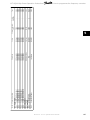
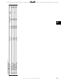
Contents
1 How to Read these Operating Instructions
5
Copyright, Limitation of Liability and Revision Rights 5
Approvals 6
Symbols 6
2 Safety
7
General Warning 8
Before commencing repair work 8
Special conditions 8
Avoid unintended start 9
Safe Stop Installation 9
Safe Stop of the Frequency Converter 11
IT mains 12
3 How to Install
13
How to Get Started 13
Pre-installation 13
Planning the Installation Site 13
Receiving the Frequency Converter 14
Transportation and Unpacking 14
Lifting 15
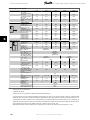
Mechanical Dimensions 17
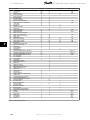
Rated Power 24
Mechanical Installation 25
Terminal locations - frame size D 26
Terminal Locations - frame size E 28
Terminal Locations - frame size F 32
Cooling and Airflow 34
Field Installation of Options 39
Installation of Duct Cooling Kit in Rittal Enclosures 39
Outside installation/ NEMA 3R kit for Rittal enclosures 42
Installation on pedestal 43
Input plate option 45
Installation of Mains Shield for frequency converters 46
Frame size F Panel Options 46
Frame size F Panel Options 46
Electrical Installation 49
Power Connections 49
Mains connection 64
Fuses 65
VLT AQUA High Power Operation Instructions Contents
MG.20.P3.02 - VLT
®
is a registered Danfoss trademark
1

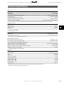
Motor Insulation 68
Motor Bearing Currents 68
Control cable routing 69
Electrical Installation, Control Terminals 70
Connection Examples 72
Start/Stop 72
Pulse Start/Stop 72
Electrical Installation - additional 74
Electrical Installation, Control Cables 74
Switches S201, S202, and S801 76
Final Set-up and Test 77
Additional Connections 79
Mechanical Brake Control 79
Motor Thermal Protection 79
4 How to operate the frequency converter
81
Ways of Operation 81
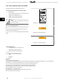
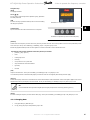
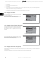
How to operate graphical LCP (GLCP) 81
How to operate numeric LCP (NLCP) 86
Tips and tricks 89
5 How to programme the frequency converter
93
How to programme 93
Q1 My Personal Menu 94
Q2 Quick Setup 94
Q5 Changes Made 96
Q6 Loggings 97
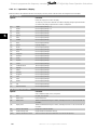
Commonly Used Parameters - Explanations 98
Main Menu 98
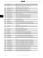
Parameter Options 138
Default settings 138
Operation/Display 0-** 139
Load/Motor 1-** 141
Brakes 2-** 142
Reference / Ramps 3-** 143
Limits / Warnings 4-** 144
Digital In/Out 5-** 145
Analog In/Out 6-** 146
Comm. and Options 8-** 147
Profibus 9-** 148
CAN Fieldbus 10-** 149
Smart Logic 13-** 150
Contents VLT AQUA High Power Operation Instructions
2
MG.20.P3.02 - VLT
®
is a registered Danfoss trademark

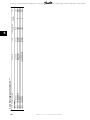
Special Functions 14-** 151
FC Information 15-** 152
Data Readouts 16-** 154
Data Readouts 2 18-** 156
FC Closed Loop 20-** 157
Ext. Closed Loop 21-** 158
Application Functions 22-** 160
Timed Actions 23-** 162
Cascade Controller 25-** 163
Analog I/O Option MCB 109 26-** 165
Cascade CTL Option 27-** 166
Water Application Functions 29-** 168
Bypass Option 31-** 169
6 General Specifications
171
7 Troubleshooting
183
Fault messages 186
Index
192
VLT AQUA High Power Operation Instructions Contents
MG.20.P3.02 - VLT
®
is a registered Danfoss trademark
3

1 How to Read these Operating Instructions VLT AQUA High Power Operation Instructions
4
MG.20.P3.02 - VLT
®
is a registered Danfoss trademark
1

1 How to Read these Operating Instructions
1.1.1 Copyright, Limitation of Liability and Revision Rights
This publication contains information proprietary to Danfoss. By accepting and using this manual the user agrees that the information contained herein
will be used solely for operating equipment from Danfoss or equipment from other vendors provided that such equipment is intended for communication
with Danfoss equipment over a serial communication link. This publication is protected under the Copyright laws of Denmark and most other countries.
Danfoss does not warrant that a software program produced according to the guidelines provided in this manual will function properly in every physical,
hardware or software environment.
Although Danfoss has tested and reviewed the documentation within this manual, Danfoss makes no warranty or representation, neither expressed nor
implied, with respect to this documentation, including its quality, performance, or fitness for a particular purpose.
In no event shall Danfoss be liable for direct, indirect, special, incidental, or consequential damages arising out of the use, or the inability to use information
contained in this manual, even if advised of the possibility of such damages. In particular, Danfoss is not responsible for any costs, including but not
limited to those incurred as a result of lost profits or revenue, loss or damage of equipment, loss of computer programs, loss of data, the costs to substitute
these, or any claims by third parties.
Danfoss reserves the right to revise this publication at any time and to make changes to its contents without prior notice or any obligation to notify former
or present users of such revisions or changes.
VLT AQUA High Power Operation Instructions 1 How to Read these Operating Instructions
MG.20.P3.02 - VLT
®
is a registered Danfoss trademark
5
1

These Operating Instructions will introduce all aspects of your VLT AQUA Drive.
Available literature for VLT AQUA Drive:
- Operating Instructions MG.20.MX.YY provide the neccessary information for getting the drive up and running.
- Design Guide MG.20.NX.YY entails technical information about the drive design and customer applications.
- Programming Guide MG.20.OX.YY provides information on how to programme and includes complete parameter descriptions.
X = Revision number
YY = Language code
Danfoss Drives technical literature is also available online at www.danfoss.com/BusinessAreas/DrivesSolutions/Documentations/Technical+Documenta-
tion.
1.1.2 Approvals
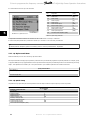
1.1.3 Symbols
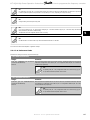
Symbols used in these Operating Instructions.
NB!
Indicates something to be noted by the reader.
Indicates a general warning.
Indicates a high-voltage warning.
* Indicates default setting
1 How to Read these Operating Instructions VLT AQUA High Power Operation Instructions
6
MG.20.P3.02 - VLT
®
is a registered Danfoss trademark
1

2Safety
2.1.1 Safety note
The voltage of the frequency converter is dangerous whenever connected to mains. Incorrect installation of the motor, frequency
converter or fieldbus may cause damage to the equipment, serious personal injury or death. Consequently, the instructions in this
manual, as well as national and local rules and safety regulations, must be complied with.
Safety Regulations
1. The frequency converter must be disconnected from mains if repair work is to be carried out. Check that the mains supply has been disconnected
and that the necessary time has passed before removing motor and mains plugs.
2. The [STOP/RESET] key on the control panel of the frequency converter does not disconnect the equipment from mains and is thus not to be
used as a safety switch.
3. Correct protective earthing of the equipment must be established, the user must be protected against supply voltage, and the motor must be
protected against overload in accordance with applicable national and local regulations.
4. The earth leakage currents are higher than 3.5 mA.
5. Protection against motor overload is set by par. 1-90
Motor Thermal Protection
. If this function is desired, set par. 1-90 to data value [ETR trip]
(default value) or data value [ETR warning]. Note: The function is initialised at 1.16 x rated motor current and rated motor frequency. For the
North American market: The ETR functions provide class 20 motor overload protection in accordance with NEC.
6. Do not remove the plugs for the motor and mains supply while the frequency converter is connected to mains. Check that the mains supply has
been disconnected and that the necessary time has passed before removing motor and mains plugs.
7. Please note that the frequency converter has voltage inputs other than L1, L2 and L3, when load sharing (linking of DC intermediate circuit) and
external 24 V DC have been installed. Check that all voltage inputs have been disconnected and that the necessary time has passed before
commencing repair work.
Installation at High Altitudes
Installation at high altitude:
380 - 480 V: At altitudes above 3 km, please contact Danfoss Drives regarding PELV.
525 - 690 V: At altitudes above 2 km, please contact Danfoss Drives regarding PELV.
Warning against Unintended Start
1. The motor can be brought to a stop by means of digital commands, bus commands, references or a local stop, while the frequency converter is
connected to mains. If personal safety considerations make it necessary to ensure that no unintended start occurs, these stop functions are not sufficient.
2. While parameters are being changed, the motor may start. Consequently, the stop key [STOP/RESET] must always be activated; following which data
can be modified. 3. A motor that has been stopped may start if faults occur in the electronics of the frequency converter, or if a temporary overload or
a fault in the supply mains or the motor connection ceases.
Warning:
Touching the electrical parts may be fatal - even after the equipment has been disconnected from mains.
Also make sure that other voltage inputs have been disconnected, such as external 24 V DC, load sharing (linkage of DC intermediate circuit), as well as
the motor connection for kinetic back up.
VLT AQUA High Power Operation Instructions 2 Safety
MG.20.P3.02 - VLT
®
is a registered Danfoss trademark
7
2

2.1.2 General Warning
Warning:
Touching the electrical parts may be fatal - even after the equipment has been disconnected from mains.
Also make sure that other voltage inputs have been disconnected, (linkage of DC intermediate circuit), as well as the motor connection
for kinetic back-up.
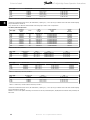
Before touching any potentially live parts of the frequency converter, wait at least as follows:
380 - 480 V, 110 - 250 kW, wait at least 20 minutes.
380 - 480 V, 315- 1000 kW, wait at least 40 minutes.
525 - 690 V, 45 - 400 kW, wait at least 20 minutes.
525 - 690 V, 450 - 1200 kW, wait at least 30 minutes.
Shorter time is allowed only if indicated on the nameplate for the specific unit.
Leakage Current
The earth leakage current from the frequency converter exceeds 3.5 mA. According to IEC 61800-5-1 a reinforced Protective Earth
connection must be ensured by means of: a min. 10mm² Cu or 16mm² Al PE-wire or an addtional PE wire - with the same cable cross
section as the Mains wiring - must be terminated separately.
Residual Current Device
This product can cause a D.C. current in the protective conductor. Where a residual current device (RCD) is used for extra protection,
only an RCD of Type B (time delayed) shall be used on the supply side of this product. See also RCD Application Note MN.90.GX.02.
Protective earthing of the frequency converter and the use of RCD's must always follow national and local regulations.
2.1.3 Before commencing repair work
1. Disconnect the frequency converter from mains
2. Disconnect DC bus terminals 88 and 89
3. Wait at least the time mentioned in section General Warning above
4. Remove motor cable
2.1.4 Special conditions
Electrical ratings:
The rating indicated on the nameplate of the frequency converter is based on a typical 3-phase mains power supply, within the specified voltage, current
and temperature range, which is expected to be used in most applications.
The frequency converters also support other special applications, which affect the electrical ratings of the frequency converter. Special
conditions which affect the electrical ratings might be:
• Single phase applications
• High temperature applications which require derating of the electrical ratings
• Marine applications with more severe environmental conditions.
Consult the relevant clauses in these instructions and in the VLT
®
AQUA Drive Design Guide for information about the electrical ratings.
Installation requirements:
The overall electrical safety of the frequency converter requires special installation considerations regarding:
• Fuses and circuit breakers for over-current and short-circuit protection
• Selection of power cables (mains, motor, brake, loadsharing and relay)
• Grid configuration (IT,TN, grounded leg, etc.)
• Safety of low-voltage ports (PELV conditions).
Consult the relevant clauses in these instructions and in the VLT
®
AQUA Drive Design Guide for information about the installation requirements.
2 Safety VLT AQUA High Power Operation Instructions
8
MG.20.P3.02 - VLT
®
is a registered Danfoss trademark
2

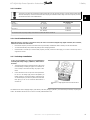
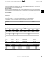
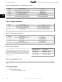
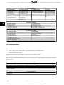
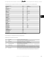
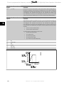
2.1.5 Caution
The frequency converter's DC link capacitors remain charged after power has been disconnected. To avoid an electrical shock hazard,
disconnect the frequency converter from the mains before carrying out maintenance. Before doing service on the frequency converter,
wait at least the amount of time indicated below:
Voltage Power size Min. Waiting Time
380 - 480 V 110 - 250 kW 20 minutes
315 - 1000 kW 40 minutes
525 - 690 V 45 - 400 kW 20 minutes
450- 1200 kW 30 minutes
Be aware that there may be high voltage on the DC link even when the LEDs are turned off.
2.1.6 Avoid unintended start
While the frequency converter is connected to mains, the motor can be started/stopped using digital commands, bus commands,
references or via the Local Control Panel.
• Disconnect the frequency converter from mains whenever personal safety considerations make it necessary to avoid unintended start.
• To avoid unintended start, always activate the [OFF] key before changing parameters.
• Unless terminal 37 is turned off, an electronic fault, temporary overload, a fault in the mains supply, or lost motor connection may cause a
stopped motor to start.
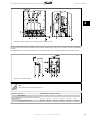
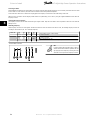
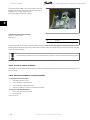
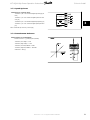
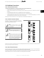
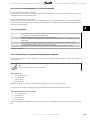
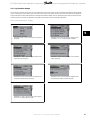
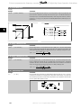
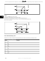
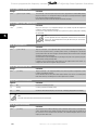
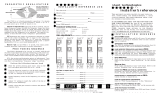
2.1.7 Safe Stop Installation
To carry out an installation of a Category 0 Stop (EN60204) in
conformity with Safety Category 3 (EN954-1), follow these in-
structions:
1. The bridge (jumper) between Terminal 37 and 24 V DC must be
removed. Cutting or breaking the jumper is not sufficient. Re-
move it entirely to avoid short-circuiting. See jumper on illus-
tration.
2. Connect terminal 37 to 24 V DC by a short-circuit protected ca-
ble. The 24 V DC voltage supply must be interruptible by an
EN954-1 Category 3 circuit interrupt device. If the interrupt de-
vice and the frequency converter are placed in the same instal-
lation panel, you can use an unscreened cable instead of a
screened one.
Illustration 2.1: Bridge jumper between terminal 37 and 24
VDC
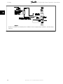
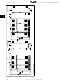
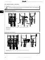
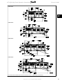
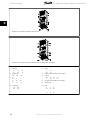
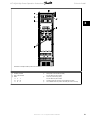
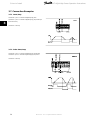
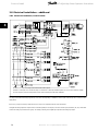
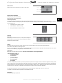
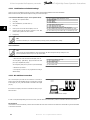
The illustration below shows a Stopping Category 0 (EN 60204-1) with safety Category 3 (EN 954-1). The circuit interrupt is caused by an opening door
contact. The illustration also shows how to connect a non-safety related hardware coast.
VLT AQUA High Power Operation Instructions 2 Safety
MG.20.P3.02 - VLT
®
is a registered Danfoss trademark
9
2

Illustration 2.2: Illustration of the essential aspects of an installation to achieve a Stopping Category 0 (EN 60204-1) with safety Category
3 (EN 954-1).
2 Safety VLT AQUA High Power Operation Instructions
10
MG.20.P3.02 - VLT
®
is a registered Danfoss trademark
2

2.1.8 Safe Stop of the Frequency Converter
For versions fitted with a Safe Stop terminal 37 input, the frequency converter can perform the safety function
Safe Torque Off
(As defined by draft CD
IEC 61800-5-2) or
Stop Category 0
(as defined in EN 60204-1).
It is designed and approved suitable for the requirements of Safety Category 3 in EN 954-1. This functionality is called Safe Stop. Prior to integration and
use of Safe Stop in an installation, a thorough risk analysis on the installation must be carried out in order to determine whether the Safe Stop functionality
and safety category are appropriate and sufficient. In order to install and use the Safe Stop function in accordance with the requirements of Safety
Category 3 in EN 954-1, the related information and instructions of the VLT AQUA Drive Design Guide MG.20.NX.YY must be followed! The information
and instructions of the Operating Instructions are not sufficient for a correct and safe use of the Safe Stop functionality!
VLT AQUA High Power Operation Instructions 2 Safety
MG.20.P3.02 - VLT
®
is a registered Danfoss trademark
11
2

2.1.9 IT mains
IT Mains
Do not connect frequency converters with RFI-filters to mains supplies with a voltage between phase and earth of more than 440 V
for 400 V converters and 760 V for 690 V converters.
For 400 V IT mains and delta earth (grounded leg), mains voltage may exceed 440 V between phase and earth.
For 690 V IT mains and delta earth (grounded leg), mains voltage may exceed 760 V between phase and earth.
par. 14-50
RFI Filter
can be used to disconnect the internal RFI capacitiors from the RFI filter to ground.
2.1.10 Software Version and Approvals
VLT AQUA Drive
Software version: 1.24
This manual can be used with all VLT AQUA Drive frequency converters with software version 1.24.
The software version number can be found in parameter 15-43.
2.1.11 Disposal instruction
Equipment containing electrical components must not be disposed of together with domestic waste.
It must be separately collected with electrical and electronic waste according to local and currently valid leg-
islation.
2 Safety VLT AQUA High Power Operation Instructions
12
MG.20.P3.02 - VLT
®
is a registered Danfoss trademark
2

3How to Install
3.1 How to Get Started
3.1.1 About How to Install
This chapter covers mechanical and electrical installations to and from power terminals and control card terminals.
Electrical installation of
options
is described in the relevant Operating Instructions and Design Guide.
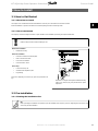
3.1.2 How to Get Started
The frequency converter is designed to achieve a quick and EMC-correct installation by following the steps described below.
Read the safety instructions before installing the unit.
Mechanical Installation
• Mechanical mounting
Electrical Installation
• Connection to Mains and Protecting Earth
• Motor connection and cables
• Fuses and circuit breakers
• Control terminals - cables
Quick setup
•Local Control Panel, LCP
• Automatic Motor Adaptation, AMA
• Programming
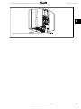
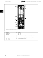
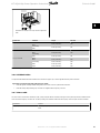
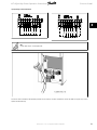
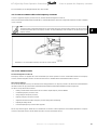
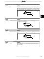
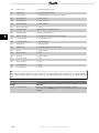
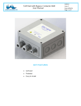
Frame size is depending on enclosure type, power range and mains volt-
age
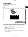
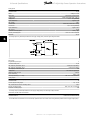
Illustration 3.1: Diagram showing basic installation including
mains, motor, start/stop key, and potentiometer for speed
adjustment.
3.2 Pre-installation
3.2.1 Planning the Installation Site
NB!
Before performing the installation it is important to plan the installation of the frequency converter. Neglecting this may result in extra
work during and after installation.
VLT AQUA High Power Operation Instructions 3 How to Install
MG.20.P3.02 - VLT
®
is a registered Danfoss trademark
13
3

Select the best possible operation site by considering the following (see details on the following pages, and the respective Design
Guides):
• Ambient operating temperature
• Installation method
• How to cool the unit
• Position of the frequency converter
•Cable routing
• Ensure the power source supplies the correct voltage and necessary current
• Ensure that the motor current rating is within the maximum current from the frequency converter
• If the frequency converter is without built-in fuses, ensure that the external fuses are rated correctly.
3.2.2 Receiving the Frequency Converter
When receiving the frequency converter please make sure that the packaging is intact, and be aware of any damage that might have occurred to the
unit during transport. In case damage has occurred, contact immediately the shipping company to claim the damage.
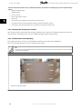
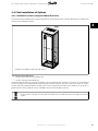
3.2.3 Transportation and Unpacking
Before unpacking the frequency converter it is recommended that it is located as close as possible to the final installation site.
Remove the box and handle the frequency converter on the pallet, as long as possible.
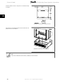
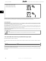
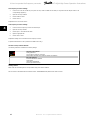
NB!
The card box cover contains a drilling master for the mounting holes in the D frames. For the E size, please refer to section
Mechanical
Dimensions
later in this chapter.
Illustration 3.2: Mounting Template
3 How to Install VLT AQUA High Power Operation Instructions
14
MG.20.P3.02 - VLT
®
is a registered Danfoss trademark
3

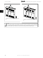
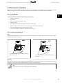
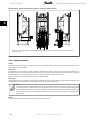
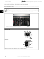
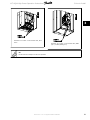
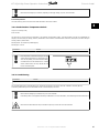
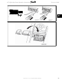
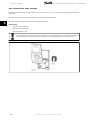
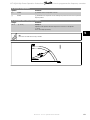
3.2.4 Lifting
Always lift the frequency converter in the dedicated lifting eyes. For all D and E2 (IP00) frames, use a bar to avoid bending the lifting holes of the frequency
converter.
Illustration 3.3: Recommended lifting method, frame sizes D and E .
NB!
The lifting bar must be able to handle the weight of the frequency converter. See
Mechanical Dimensions
for the weight of the different
frame sizes. Maximum diameter for bar is 25 cm (1 inch). The angle from the top of the drive to the lifting cable should be 60 degrees
or greater.
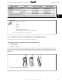
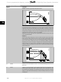
Illustration 3.4: Recommended lifting method, frame size
F1.
Illustration 3.5: Recommended lifting method, frame size
F2.
VLT AQUA High Power Operation Instructions 3 How to Install
MG.20.P3.02 - VLT
®
is a registered Danfoss trademark
15
3

Illustration 3.6: Recommended lifting method, frame size
F3.
Illustration 3.7: Recommended lifting method, frame size
F4.
NB!
Note the plinth is provided in the same packaging as the frequency converter but is not attached to F1-F4 frames during shipment.
The plinth is required to allow airflow to the drive to provide proper cooling. The F frames should be positioned on top of the plinth in
the final installation location. The angle from the top of the drive to the lifting cable should be 60 degrees or greater.
3 How to Install VLT AQUA High Power Operation Instructions
16
MG.20.P3.02 - VLT
®
is a registered Danfoss trademark
3

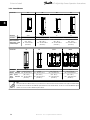
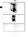
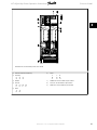
*
Please note airflow directions
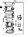
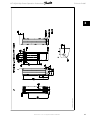
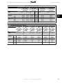
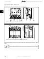
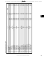
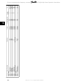
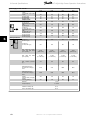
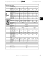
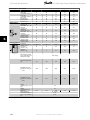
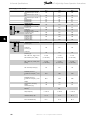
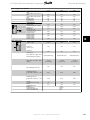
3.2.5 Mechanical Dimensions
VLT AQUA High Power Operation Instructions 3 How to Install
MG.20.P3.02 - VLT
®
is a registered Danfoss trademark
17
3

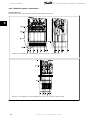
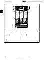
*
Please note airflow directions
3 How to Install VLT AQUA High Power Operation Instructions
18
MG.20.P3.02 - VLT
®
is a registered Danfoss trademark
3

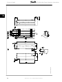
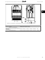
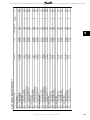
*
Please note airflow directions
VLT AQUA High Power Operation Instructions 3 How to Install
MG.20.P3.02 - VLT
®
is a registered Danfoss trademark
19
3

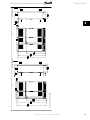
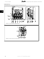
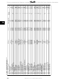
*
Please note airflow directions
3 How to Install VLT AQUA High Power Operation Instructions
20
MG.20.P3.02 - VLT
®
is a registered Danfoss trademark
3
Page is loading ...
Page is loading ...
Page is loading ...
Page is loading ...
Page is loading ...
Page is loading ...
Page is loading ...
Page is loading ...
Page is loading ...
Page is loading ...
Page is loading ...
Page is loading ...
Page is loading ...
Page is loading ...
Page is loading ...
Page is loading ...
Page is loading ...
Page is loading ...
Page is loading ...
Page is loading ...
Page is loading ...
Page is loading ...
Page is loading ...
Page is loading ...
Page is loading ...
Page is loading ...
Page is loading ...
Page is loading ...
Page is loading ...
Page is loading ...
Page is loading ...
Page is loading ...
Page is loading ...
Page is loading ...
Page is loading ...
Page is loading ...
Page is loading ...
Page is loading ...
Page is loading ...
Page is loading ...
Page is loading ...
Page is loading ...
Page is loading ...
Page is loading ...
Page is loading ...
Page is loading ...
Page is loading ...
Page is loading ...
Page is loading ...
Page is loading ...
Page is loading ...
Page is loading ...
Page is loading ...
Page is loading ...
Page is loading ...
Page is loading ...
Page is loading ...
Page is loading ...
Page is loading ...
Page is loading ...
Page is loading ...
Page is loading ...
Page is loading ...
Page is loading ...
Page is loading ...
Page is loading ...
Page is loading ...
Page is loading ...
Page is loading ...
Page is loading ...
Page is loading ...
Page is loading ...
Page is loading ...
Page is loading ...
Page is loading ...
Page is loading ...
Page is loading ...
Page is loading ...
Page is loading ...
Page is loading ...
Page is loading ...
Page is loading ...
Page is loading ...
Page is loading ...
Page is loading ...
Page is loading ...
Page is loading ...
Page is loading ...
Page is loading ...
Page is loading ...
Page is loading ...
Page is loading ...
Page is loading ...
Page is loading ...
Page is loading ...
Page is loading ...
Page is loading ...
Page is loading ...
Page is loading ...
Page is loading ...
Page is loading ...
Page is loading ...
Page is loading ...
Page is loading ...
Page is loading ...
Page is loading ...
Page is loading ...
Page is loading ...
Page is loading ...
Page is loading ...
Page is loading ...
Page is loading ...
Page is loading ...
Page is loading ...
Page is loading ...
Page is loading ...
Page is loading ...
Page is loading ...
Page is loading ...
Page is loading ...
Page is loading ...
Page is loading ...
Page is loading ...
Page is loading ...
Page is loading ...
Page is loading ...
Page is loading ...
Page is loading ...
Page is loading ...
Page is loading ...
Page is loading ...
Page is loading ...
Page is loading ...
Page is loading ...
Page is loading ...
Page is loading ...
Page is loading ...
Page is loading ...
Page is loading ...
Page is loading ...
Page is loading ...
Page is loading ...
Page is loading ...
Page is loading ...
Page is loading ...
Page is loading ...
Page is loading ...
Page is loading ...
Page is loading ...
Page is loading ...
Page is loading ...
Page is loading ...
Page is loading ...
Page is loading ...
Page is loading ...
Page is loading ...
Page is loading ...
Page is loading ...
Page is loading ...
Page is loading ...
Page is loading ...
Page is loading ...
Page is loading ...
Page is loading ...
Page is loading ...
Page is loading ...
Page is loading ...
Page is loading ...
Page is loading ...
Page is loading ...
Page is loading ...
Page is loading ...
Page is loading ...
Page is loading ...
Page is loading ...
Page is loading ...
Page is loading ...
-
 1
1
-
 2
2
-
 3
3
-
 4
4
-
 5
5
-
 6
6
-
 7
7
-
 8
8
-
 9
9
-
 10
10
-
 11
11
-
 12
12
-
 13
13
-
 14
14
-
 15
15
-
 16
16
-
 17
17
-
 18
18
-
 19
19
-
 20
20
-
 21
21
-
 22
22
-
 23
23
-
 24
24
-
 25
25
-
 26
26
-
 27
27
-
 28
28
-
 29
29
-
 30
30
-
 31
31
-
 32
32
-
 33
33
-
 34
34
-
 35
35
-
 36
36
-
 37
37
-
 38
38
-
 39
39
-
 40
40
-
 41
41
-
 42
42
-
 43
43
-
 44
44
-
 45
45
-
 46
46
-
 47
47
-
 48
48
-
 49
49
-
 50
50
-
 51
51
-
 52
52
-
 53
53
-
 54
54
-
 55
55
-
 56
56
-
 57
57
-
 58
58
-
 59
59
-
 60
60
-
 61
61
-
 62
62
-
 63
63
-
 64
64
-
 65
65
-
 66
66
-
 67
67
-
 68
68
-
 69
69
-
 70
70
-
 71
71
-
 72
72
-
 73
73
-
 74
74
-
 75
75
-
 76
76
-
 77
77
-
 78
78
-
 79
79
-
 80
80
-
 81
81
-
 82
82
-
 83
83
-
 84
84
-
 85
85
-
 86
86
-
 87
87
-
 88
88
-
 89
89
-
 90
90
-
 91
91
-
 92
92
-
 93
93
-
 94
94
-
 95
95
-
 96
96
-
 97
97
-
 98
98
-
 99
99
-
 100
100
-
 101
101
-
 102
102
-
 103
103
-
 104
104
-
 105
105
-
 106
106
-
 107
107
-
 108
108
-
 109
109
-
 110
110
-
 111
111
-
 112
112
-
 113
113
-
 114
114
-
 115
115
-
 116
116
-
 117
117
-
 118
118
-
 119
119
-
 120
120
-
 121
121
-
 122
122
-
 123
123
-
 124
124
-
 125
125
-
 126
126
-
 127
127
-
 128
128
-
 129
129
-
 130
130
-
 131
131
-
 132
132
-
 133
133
-
 134
134
-
 135
135
-
 136
136
-
 137
137
-
 138
138
-
 139
139
-
 140
140
-
 141
141
-
 142
142
-
 143
143
-
 144
144
-
 145
145
-
 146
146
-
 147
147
-
 148
148
-
 149
149
-
 150
150
-
 151
151
-
 152
152
-
 153
153
-
 154
154
-
 155
155
-
 156
156
-
 157
157
-
 158
158
-
 159
159
-
 160
160
-
 161
161
-
 162
162
-
 163
163
-
 164
164
-
 165
165
-
 166
166
-
 167
167
-
 168
168
-
 169
169
-
 170
170
-
 171
171
-
 172
172
-
 173
173
-
 174
174
-
 175
175
-
 176
176
-
 177
177
-
 178
178
-
 179
179
-
 180
180
-
 181
181
-
 182
182
-
 183
183
-
 184
184
-
 185
185
-
 186
186
-
 187
187
-
 188
188
-
 189
189
-
 190
190
-
 191
191
-
 192
192
-
 193
193
-
 194
194
-
 195
195
-
 196
196
-
 197
197


Danfoss VLT AQUA Drive FC 202 Operating instructions
- Type
- Operating instructions
- This manual is also suitable for
Ask a question and I''ll find the answer in the document
Finding information in a document is now easier with AI
Related papers
-
Danfoss VLT AQUA Drive FC 202 Programming Guide
-
-
-
Danfoss VLT® HVAC Drive Programming Guide
-
-
-
Danfoss VLT AutomationDrive FC 302 Installation guide
-
-
-
Danfoss VLT® AQUA Drive User guide
Other documents
-
Siemens WXTS1231 User manual
-
-
 Xtant P500 Installer's Reference Manual
-
 Xtant P500 User manual
-
Rittal TopTherm LCP Hybrid 3311.700 Assembly And Operating Instructions Manual
-
 Cooper Bussmann Power Module PS User manual
-
Eaton PXR-PCAM Instruction Leaflet
-
 Goldline Aqua Pod Operating instructions
-
 United Automation SSC-6kW User manual
-
ABB SEMIS Simulation Tool Isolated DC-DC Converter User manual


