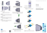
Automation Direct CFW100-CRS485 RS485 Module User guide

Type
User guide

This manual is also suitable for

Motors | Automation | Energy | Transmission & Distribution | Coatings
RS485 Module
Módulo RS485
CFW100
Installation, Configuration and
Operation Guide
Guía de Instalación, Configuración
y Operación
Guia de Instalação, Configuração
e Operação
English / Español / Português
Summary / Índice
English
EspañolPortuguês
Summary
1 SAFETY INFORMATION ................................5
1.1 SAFETY WARNINGS ....................................... 5
1.2 PRELIMINARY RECOMMENDATIONS .......... 5
2 GENERAL INFORMATION ............................5
3 PACKAGE CONTENT ...................................5
4 INSTALLATION OF THE ACCESSORY ........6
5 CONFIGURATIONS .......................................6
APPENDIX A – FIGURES ................................16
Índice
1 INFORMACIONES DE SEGURIDAD ............9
1.1 AVISOS DE SEGURIDAD ................................9
1.2 PRELIMINARY RECOMMENDATIONS .......... 9
2 INFORMACIONES GENERALES ..................9
3 CONTENIDO DEL EMBALAJE ....................9
4 INSTALACIÓN DEL ACCESORIO...............10
5 CONFIGURACIONES ..................................10
ANEXO A – FIGURAS ......................................16
Índice
1 INFORMAÇÕES DE SEGURANÇA .............13
1.1 AVISOS DE SEGURANÇA .............................13
1.2 RECOMENDAÇÕES PRELIMINARES .........13
2 INFORMAÇÕES GERAIS ............................13
3 CONTDO DA EMBALAGEM ..................13
4 INSTALAÇÃO DO ACESRIO ..................14
5 CONFIGURAÇÕES ......................................14
ANEXO A – FIGURAS ......................................16
RS485 Module
CFW100 | 5
English
1 SAFETY INFORMATION
1.1 SAFETY WARNINGS
NOTE!
Only use the RS485 module (CFW100-
CRS485) on WEG CFW100 series inverters.
It is recommended reading the CFW100
User’s Manual before installing or operating
this accessory.
The content of this guide provides important
information for the full understanding and
proper operation of this module.
1.2 PRELIMINARY RECOMMENDATIONS
ATTENTION!
Always disconnect the general power supply
before connecting or disconnecting the
accessories of the CFW100 frequency
inverter.
Wait for at least ten minutes for the full
discharge of the inverter.
2 GENERAL INFORMATION
This guide provides directions for the installation,
configuration and operation of the RS485 module
(CFW100-CRS485).
3 PACKAGE CONTENT
Upon receiving the product, check if the package contains:
Accessory in anti-static package.
Installation, configuration and operation guide.
RS485 Module
6 | CFW100
English
4 INSTALLATION OF THE ACCESSORY
The CFW100-CRS485 is easily connected to the CFW100
frequency inverter by means of the plug-and-play
concept. The procedures below must be observed for
the proper installation and start-up:
1. With the inverter de-energized, remove the front cover
of the inverter shown in figure A.1 (a).
2. Fit the accessory to be installed as shown in figure A.1 (b).
3. Power up the inverter.
5 CONFIGURATIONS
The RS485 interface connections must be done on the
connector as per table 1.
Tabl e 1: Connector signals of the RS485 interface
Connector Description
6 RS485 - B RS485 (Terminal B)
7 RS485 - A RS485 (Terminal A)
8 0 V Reference 0 V
9 PE Grounding connection
10 - ---------------------
The location of the DIP switch to select the RS485
network termination can be better viewed in figure A.2
and it must be configure as per table 2.
RS485 Module
CFW100 | 7
English
Tabl e 2: Configuration of the switches to configure the RS485
Comunication Switch Switch Setting Option
SR
S1
(*)
S1.1 = OFF and
S1.2 = OFF
RS485
Termination off
S1.1 = ON and
S1.2 = ON
RS485
Termination
on
(**)
(*) Any other combination of the switches is not allowed.
(**) It is recommended to use this termination with cables longer than 3 m.
NOTE!
The mini USB connector (see figure
A.2) is used for communication with the
CFW100-KHMIR kit only.
The use of the mini USB connector for
other connections is not permitted.
NOTE!
The use of 38400-bps serial baud rate
(P310=2) with the vector control mode V V W
(P202=5) is not allowed. This condition
activates the Config state (Conf) so as to
indicate parameterization incompatibility.
For further details, refer to chapter 5 of the
CFW100 programming manual.
RS485 Module
8 | CFW100
English
Appendix A - Anexo A
CFW100 | 17
DIP-switch
1
ON
2
Conector interface
RS485
Mini USB
32.3 [1.27 ]
53 [2.09]
21.8 [0.86]
Figure A.2: CFW100-CRS485 dimensions in mm [in] and
connectors location
Figura A.2: Dimensiones del CFW100-CRS485 en mm [in]
y localización de los conectadores
Figura A.2: Dimensões do CFW100-CRS485 em mm [in] e
localização dos conectores
Document: 10001433110 / 01
WEG Drives & Controls - Automação LTDA.
Jaraguá do Sul - SC - Brazil
Phone 55 (47) 3276-4000 - Fax 55 (47) 3276-4020
São Paulo - SP - Brazil
Phone 55 (11) 5053-2300 - Fax 55 (11) 5052-4212
automacao@weg.net
www.weg.net
11880376
  • Page 1 1
  • Page 2 2
  • Page 3 3
  • Page 4 4
  • Page 5 5
  • Page 6 6
  • Page 7 7
  • Page 8 8
  • Page 9 9
  • Page 10 10
  • Page 11 11
  • Page 12 12
  • Page 13 13
  • Page 14 14
  • Page 15 15
  • Page 16 16
  • Page 17 17
  • Page 18 18
  • Page 19 19
  • Page 20 20

Automation Direct CFW100-CRS485 RS485 Module User guide

Type
User guide
This manual is also suitable for

Ask a question and I''ll find the answer in the document

Finding information in a document is now easier with AI