Page is loading ...

High Effi ciency Gas-Fired Hot Water
Direct Vent Condensing Boilers
SUPPLEMENTAL INSTALLATION INSTRUCTIONS FOR ALL
APPROVED VENT SYSTEMS (CPVC/PVC AND PPS)
107198-01 - 7/16
Velocity Boiler Works, LLC
P.O. Box 14818
3633 I Street
Philadelphia, PA 19134
9700609
WARNING
Improper installation, adjustment, alteration, service or maintenance can cause property damage,
injury, or loss of life. For assistance or additional information, consult a qualifi ed installer, service
agency or the gas supplier. This boiler requires a special venting system. Read these instructions
carefully before installing.
VELOCITY LOGO CMYK COLORS
NOTICE
This manual covers vent system installation only. It includes some vent options that are approved
for use with this boiler but not shown in the boiler’s installation manual. This supplement effectively
replaces Section VII (venting) in Installation manual part number 106916-01. See Installation manual
part number 106916-01 for all other aspects of installation, such as piping and wiring, as well for
service and maintenance instructions.

2
Table of Contents
VII. Venting
A. General Vent System Design 3
B. Design Requirements Unique to Horizontal Twin Pipe
Venting Systems 9
C. Design Requirements Unique to Vertical Venting Systems 15
D. Design Requirements Unique to Split Vent Systems 23
E. Assembly of CPVC/PVC Vent Systems 31
F. Assembly of DuraVent PolyPro Vent Systems 37
G.AssemblyofSelkirkPolyueVentSystems 42
H.AssemblyofCentrothermInnoueVentSystems 46
I. Condensate Trap and Drain 50
J. Removing An Existing Boiler From Common Chimney 51
Appendix A: Special Requirements For Side-Wall 52
Vented Appliances In The Commonwealth
of Massachusetts

3
VII Venting
A. General Vent System Design
There are three basic ways to vent this boiler:
• Horizontal (“Side Wall”) Twin Pipe Venting (Figure 7.0a) - Vent system exits the building through an outside wall.
Combustionairanduegasareroutedbetweentheboilerandtheterminal(s)usingseparatepipesforatleastpartofthe
way. A summary of Horizontal Twin Pipe venting options is shown in Table 7.5.
• Vertical Twin Pipe Venting (Figure 7.0b)-Ventsystemexitsthebuildingthrougharoof.Combustionairanduegas
areroutedbetweentheboilerandtheterminal(s)usingseparatepipesforatleastpartoftheway.AsummaryofVertical
Twin Pipe venting options is shown in Table 7.13
• Split Venting (Figure 7.0c) - Exhaust system exits the building through a roof, and combustion air is drawn from a
terminal mounted on the side wall. A summary of split venting options is shown in Table 7.21
All of these systems are considered “direct vent” because the air for combustion is drawn directly from the outdoors into the
boiler. One of the vent option columns in Tables 7.5, 7.13 or 7.21 must match the planned vent and air intake system exactly.
Design details applying to all vent systems are shown in this section. Observe all design requirements in this section, as well as
those unique to the type of system being installed:
• B - Design Requirements Unique to Horizontal Twin Pipe Vent Systems
• C - Design Requirements Unique to Vertical Twin Pipe Vent systems
• D - Design Requirements Unique to Split Vent Systems
WARNING
• Asphyxiation Hazard. Failure to vent this boiler in accordance with these instructions could cause
products of combustion to enter the building resulting in severe property damage, personal injury
or death.
• Do not interchange vent systems or materials unless otherwise specied.
• The use of thermal insulation covering vent pipe and ttings is prohibited.
• Do not use a barometric damper, draft hood or vent damper with this boiler.
• When using the CPVC/PVC vent option, the use of CPVC is required when venting in vertical or
horizontal chase ways.
• Any CPVC vent materials supplied with this boiler do not comply with B149.1.S1-07 and are not
approved for use in Canadian jurisdictions that require vent systems be listed to ULC S636-2008. In
these jurisdictions, vent this boiler using a listed ULC S636 Class IIB venting system.
• Do not locate vent termination where exposed to prevailing winds. Moisture and ice may form on
surface around vent termination. To prevent deterioration, surface must be in good repair (sealed,
painted, etc.).
• Do not locate air intake vent termination where chlorines, chlorouorocarbons (CFC’s), petroleum
distillates, detergents, volatile vapors or other chemicals are present. Severe boiler corrosion and
failure will result.
• The use of cellular core PVC (ASTM F891), cellular core CPVC or Radel (polyphenolsulfone) is
prohibited.
• Do not locate vent termination under a deck.
• Do not reduce specied diameters of vent and combustion air piping.
• When installing vent pipe through chimney, as a chase, no other appliance can be vented into the
chimney.
• Do not allow low spots in the vent where condensate may pool.

4
FIGURE 7.0 BASIC VENT OPTIONS
FIGURE 7.0a: HORIZONTAL TWIN PIPE
FIGURE 7.0b: VERTICAL TWIN PIPE
FIGURE 7.0c: SPLIT VENTING

5
1. Approved Vent Systems and Materials – The following materials and vent systems may be used to vent this boiler:
• CPVC–UseonlyCPVClistedtoASTMF441.InCanada,thispipemustalsobelistedtoULCS636.
• PVC–PVCmaybeusedonlyaspermittedinthismanual.AllPVCmustbelistedtoASTMD2665.Atleast30”of
CPVC pipe, and at least one CPVC elbow, must be installed between the boiler’s vent connection and the PVC pipe. Use
of foam core PVC is not permitted for venting. PVC vent pipe may not be used to vent this boiler in Canada.
• DuraVentPolyPro-ULCS636listedpolypropylenespecialgasventsystem.
• SelkirkPolyue-ULCS636listedpolypropylenespecialgasventsystem.
• CentrothermInnoFlueSW-ULCS636listedpolypropylenespecialgasventsystem.
Use PVC and/or CPVC for the air intake system. PVC may be used for all air intake piping between the intake terminal and
the boiler.
When CPVC and/or PVC pipe is used, it must be joined using primer and cement that is listed for use with the pipe material
beingjoined(PVC,CPVC,orCPVCtoPVC).
2. Vent Kits Available for Use with this Boiler – The following vent kits are available for CPVC/PVC vent systems installed
with this boiler in the USA:
• 107039-01 - 2” CPVC/PVC Vent Kit
• 107039-02 – 3” CPVC/PVC Vent Kit
These kits include the following:
(1) 30”CPVCStraightPipe
(1) 90degreeshortbendCPVCElbow
(1) StraightPVCCoupling(forexhaustterminal)
(1) 90degreePVCElbow(forintaketermination)
(2) Rodentscreens
TheCPVCPipeandelbowsuppliedwiththesekitsarenotlistedtoULCS636andmaynotbeusedinCanada.
3. Maximum Vent and Air Intake Lengths - The maximum length of the vent air intake piping depends upon the vent option
selected and the boiler size. See Tables 7.5, 7.13 or 7.21 for the maximum vent lengths. These maximum lengths apply
toboththeventandintakepiping(e.g.Option1mayhaveupto60ftofintakeand60ftofventpiping).Forallvent
systems,thelengthsshowninTables7.5,7.13and7.21areinadditiontotherst90°elbow.Ifmoreelbowsaredesired,
the maximum allowable vent length must be reduced by the amount shown in Table 7.1 for each additional elbow used.
Terminationttingsarenevercounted.
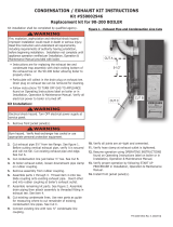
ItisrecommendedthatalleldsuppliedPVCorCPVCelbowsbe“1/4Bend”(Sanitary90°El)or“LongSweep1/4Bend”
typeelbows(Figure7.2).Inthismanual“sanitary”and“longsweep”elbowsaretreatedashavingthesameequivalent
length.
Example:
A 3” twin pipe horizontal CPVC/PVC vent system is planned for a horizontally vented 120MBH model which has the
following components in the vent system:
• 1 ft CPVC Straight Pipe
• 90 CPVC Elbow (short bend)
• 1-1/2 ft CPVC Straight Pipe
• Coupling
• 10 ft PVC Straight Pipe
• 90 PVC Elbow (Sanitary Elbow Design)
• 15 ft PVC Straight Pipe
• PVC Coupling Terminal
The Vent Option #2 column in Table 7.5 describes a horizontal direct vent system using 3” CPVC and PVC pipe. From this
column, we see that the boiler may have a vent length of up to 135ft. The rst CPVC 90 degree elbow is not considered. From
Table 7.1, we see that the equivalent length of the 90 PVC elbow is 4ft and that the equivalent length of the coupling is 0ft.
NOTICE
When 3” venting is used with the 80 or 100 models, a 2” x 3” CPVC Increaser and a short length of 2”
CPVC pipe will be required to adapt from the 2” vent collar to the 3” components in the 107039-02 kit.
These items are not included in the kit itself.

6
The total equivalent length of the planned venting system is therefore:
1ft (Straight CPVC) + 0ft (rst short bend CPVC 90 Elbow) + 1.5ft (Straight CPVC) + 0ft (Coupling) + 10ft (Straight PVC)
+ 4ft (PVC 90 Sanitary Elbow) + 15ft (Straight PVC) + 0ft (Coupling Terminal) = 31.5ft.
Since Table 7.5 shows a maximum allowable vent length of 135ft, the planned vent system length is acceptable
TheexventingusedonsomeoftheVerticalTwinPipeandSplitVentOptionsalsoreducesthemaximumallowablevent
length. See Sections VII-C or VII-D for details.
4. Minimum Vent and Air Intake Lengths - Observe the minimum vent lengths shown in Tables 7.1, 7.13 and 7.21.
5. Clearances to Combustibles - Maintain the following clearances from the vent system to combustible construction:
• Vent-1/4”(alsoobserveclearancesthroughbothcombustibleandnon-combustiblewalls-see9below)
• Air Intake - 0”
• Concentric Portion of Concentric Terminals - 0”
6. Pitch of Horizontal Vent Piping - Pitch all horizontal vent piping so that any condensate which forms in the piping will run
towards the boiler.
• PitchCPVC/PVCventpiping1/4”perfoot.
• Pitch polypropylene vent piping 5/8” per foot.
Les chaudières de catégories I, II et IV doivent présenter des tronçons horizontaux dont la pente montante est d’au moins
5/8poparpied(52mm/m)entrelachaudièreetl’évent.
TABLE 7.1: VENT/ AIR INTAKE FITTING EQUIVALENT LENGTH
CPVC/PVC FITTING EQUIVALENTLENGTH(ft) POLYPRO, POLYFLUE OR INNOFLUE
VENT FITTING
EQUIVALENTLENGTH(ft)
2”90ELBOW(“SANITARYBEND”) 2.6 2” 90 ELBOW 4.5
3”90ELBOW(“SANITARYBEND”) 4.0 3” 90 ELBOW 8.7
2”90ELBOW(“SHORTBEND”) 6.0 2”45ELBOW 2.5
3”90ELBOW(“SHORTBEND”) 10.0 3”45ELBOW 4.6
2”45ELBOW 1.5
3”45ELBOW 2.0
2” COUPLING 0.0
3” COUPLING 0.0
NOTICE
Do not exceed maximum vent/combustion air system length. Refer to Tables 7.1, 7.13 and 7.21 in this
section for maximum vent/combustion air system length.
Use only vent and combustion air terminals and terminal locations shown in Tables 7.1, 7.13 and 7.21
and related Figures.

7
FIGURE 7.2: CPVC AND PVC ELBOWS
7. Supporting Pipe - Vertical and horizontal sections of pipe must be properly supported. Maximum support spacing is as
follows:
• SupportCPVC/PVChorizontallyandverticallyevery4feet.
• Support DuraVent Polypro horizontally near the female end of each straight section of pipe and vertically every 10 feet.
• SupportCentrothermInnouehorizontallyevery39incheswithadditionalsupportsatelbowsandverticallyevery78”.
• Support2”SelkirkPolyuehorizontallyevery30”.Support3”Polyuehorizontallyevery39”.Supportverticalrunsof
both2”and3”Polyueevery16ft.
Les instructions d´installation du système d´évacuation doivent préciser que les sections horizontales doivent être
supportéespourprévenirleéchissement.Lesméthodesetlesintervallesdesupportdoiventêtrespéciés.Les
instructions divent aussi indiquer les renseignements suivants:
• les chaudières de catégories II et IV doivent être installées de façon à empêcher l´accumulation de condensat: et
• si nécessaire, les chaudières de catégories II et IV doivent être pourvues de dispositifs d´évacuation du condensat.
8. Allowing for Thermal Expansion -
• Design the vent system to allow 3/8” of thermal expansion for every 10ft of CPVC/PVC pipe. The boiler will always
act as an anchor to one end of the vent system. If at all possible, select and install hangers and wall thimbles so that
the vent system can expand towards the terminal. When a straight run of pipe exceeds 20ft and must be restrained at
bothends,anoffsetorexpansionloopmustbeprovided(Figures 7.3a, 7.3b).When a straight horizontal run of pipe
exceeds 20ft and is restrained at one end with an elbow at the other, avoid putting a hanger or guide less than “Y”
inchesfromtheelbowintheadjoiningstraightsection(Figure7.3c).Thermalexpansionttingsarenotpermitted.
• Whenproperlyassembled,expansionofPolypro,PolyueandInnoueventsystemsisaccommodatedatthejoints.See
Part VII-F, G & H of this manual for details.
9. Running PVC Vent Pipe Inside Enclosures and Through Walls - PVC vent pipe must be installed in a manner that permits
adequate air circulation around the outside of the pipe:
• Do not enclose PVC venting - Use CPVC in enclosed spaces, even if PVC is installed upstream.
• PVC venting may not be used to penetrate combustible or non-combustible walls unless all of the following conditions
are met:
a. Thewallpenetrationisatleast66inchesfromtheboilerasmeasuredalongthevent.
b. The wall is 12” thick or less
c. AnairspaceofatleastthatshowninFigure7.4ismaintainedaroundtheODofthevent.
If any of these conditions cannot be met, use CPVC for the wall penetration.
10. Vent Manufacturer’s Instructions – The vent system manufacturer may have additional vent system design requirements.
Readandfollowtheventmanufacturer’sinstructionsinadditiontothoseshownhere.Whereaconictarisesbetweenthe
two sets of instructions, the more restrictive requirements shall govern.

8
FIGURE 7.3: EXPANSION LOOPS FOR CPVC/PVC PIPE
FIGURE 7.3bFIGURE 7.3a
FIGURE 7.3c
FIGURE7.4:WALLPENETRATIONCLEARANCESFORPVCVENTPIPE

9
B. Design Requirements Unique to Horizontal Twin Pipe Venting Systems
Table 7.5 summarizes all horizontal twin pipe vent options. Illustrations of horizontal twin pipe vent systems are shown in
Figures7.6–7.10.InadditiontotherequirementsinPartVII-A,observethefollowingdesignrequirements:
1. Permitted Terminals for Horizontal Venting:
TerminalOptionA:Fittings(AcceptableforVentOptions1-8)–Ventterminatesinaplainend(couplingforPVC,bell
endforPolypro,PolyueandplainendpipeforInnoFlue).IntaketerminatesinaPVC90sweepelbowpointingdown.
Outeredgeofbothterminalsmustbewithin10”ofthewallsurface(Figures7.6,7.9).ThesectionofDuraVentPolypro,
CentrothermInnoFlueorSelkirkPolyueexposedtotheoutdoorsmustbeUVresistant.
Useofrodentscreensisgenerallyrecommendedforbothterminations.Thesecanbefabricatedfrom2”x2”(1/2”mesh)
stainlesssteelscreenandareinstalledasshowninFigure7.28.Rodentscreens(“birdguards”)forPolyPro,InnoFlueand
Polyueareasfollows:
Size/VentSystem RodentScreen(“BirdGuard”)
2” Polypro DuraVent # 2PPS-BG
3” Polypro DuraVent # 3PPS-BG
2”Polyue Selkirk#2PF-HVST
3”Polyue Selkirk#3PV-HVST
2” InnoFlue Centrotherm # IASPP02
3” InnoFlue Centrotherm # IASPP03
Ifnecessarytoachieverequiredclearanceabovegrade,CPVCorCPVC/PVCventsystemsmaybeterminatedusingttings
on snorkels as shown in Figure 7.12. When this is done, the equivalent length of all pipe on the exterior of the building,
exceptfortheterminalttingsthemselves,mustbecountedwhencalculatingtheequivalentlength.Themaximumvertical
runofthesnorkelis7feet.Braceboththeventandinletpipingifrequired.Polypro,InnoFlueandPolyuemaynotbe
snorkeled.
TerminalOptionB:IpexLowProleTerminal(AcceptableforVentOptions1,2) – This terminal is shown in Figure 7.7. If
theterminalisorientedvertically(alternateorientationshowninFig7.7)theexhaustopeningmustbeonthetopasshown.
See Part VII-E of this manual and the Ipex instructions provided with the terminal, for installation details.
TerminalOptionC:Diversitech“LowProle”Terminal(AcceptableforVentOptions1,2) – This terminal is shown in Figure
7.7.Iftheterminalisorientedvertically(alternateorientationshowninFig7.7)theexhaustopeningmustbeonthetopas
shown. See Part VII-E of this manual and the Diversitech instructions provided with the terminal, for installation details.
TerminalOptionD:IpexFGVConcentricTerminal(AcceptableforVentOptions1,2) - This terminal is shown in Figure 7.8
and may be used with CPVC/PVC vent systems. This terminal is available in various lengths and in both PVC and CPVC.
Terminals acceptable for use with these vent options are as follows:
Ipex PN FGV Concentric Terminal Description
196005 2x16”PVC
196105 2x28”PVC
196125 2x40”PVC
196006 3x20”PVC
196106 3x32”PVC
196116 3x44”PVC
197107 3 x 32” CPVC
197117 3x44”CPVC
See Part VII-E of this manual and the Ipex instructions provided with the terminal, for installation details.
TerminalOptionE:DiversitechConcentricTerminal(AcceptableforVentOptions1,2) - This terminal is shown in Figure 7.8
and may be used with CPVC/PVC vent systems. See Part VII-E of this manual and the Diversitech instructions provided with
the terminal, for installation details.
TerminalOptionF:DuraVentPolyProConcentricTerminal(AcceptableforVentOptions3,4) - This terminal is shown in
Figure 7.10 and may be used with DuraVent 2” or 3” PolyPro vent systems. See Part VII-F of this manual and the DuraVent
instructions provided with the terminal, for installation details.

10
Table 7.5: Summary of Horizontal Twin Pipe Venting Options
Vent Option 1 2 3 4 5 6 7 8
Illustrated in Figure
7.6,7.7,
7.8
7.6,7.7,
7.8
7.9, 7.10 7.9, 7.10 7.9 7.9 7.9 7.9
Pipe
Penetration
through
Structure
Vent Wall Wall Wall Wall Wall Wall Wall Wall
Intake Wall Wall Wall Wall Wall Wall Wall Wall
Material
Vent
CPVC/
PVC
(Note2)
CPVC/
PVC
(Note2)
DuraVent
PolyPro
(Rigid)
DuraVent
PolyPro
(Rigid)
Selkirk
Polyue
Selkirk
Polyue
Centro-
therm
InnoFlue
SW
Centro-
therm
InnoFlue
SW
Intake PVC PVC PVC PVC PVC PVC PVC PVC
Nominal
Diameter
Vent 2” 3” 2” 3” 2” 3” 2” 3”
Intake 2” 3” 2” 3” 2” 3” 2” 3”
Min Equivalent Vent Length:
Models
080 12” 12” 12” 12” 12” 12” 12” 12”
100 12” 12” 12” 12” 12” 12” 12” 12”
120
Not
Permitted
12”
Not
Permitted
12”
Not
Permitted
12”
Not
Permitted
12”
150 52” 52” 52” 52”
180 52” 52” 52” 52”
MaxEquivalentVentLength(Note1):
Models
080 60ft 135ft 60ft 135ft 60ft 135ft 60ft 135ft
100 60ft 135ft 60ft 135ft 60ft 135ft 60ft 135ft
120
Not
Permitted
135ft
Not
Permitted
135ft
Not
Permitted
135ft
Not
Permitted
135ft
150 135ft 135ft 135ft 135ft
180 135ft 135ft 135ft 135ft
Terminal
Option A
(Fittings)
Vent
Coupling
w Screen
(Note3)
Coupling
w Screen
(Note3)
2PPS-12B
or
2PPS-36B
w Screen
3PPS-12B
or
3PPS-36B
w Screen
2PF-10UV
or
2PF-39UV
w Screen
3PF-10UV
or
3PF-39UV
w Screen
ISEP02 or
ISEP0239
w Screen
ISEP03 or
ISEP0339
w Screen
Intake
Elbow w
Screen
(Note3)
Elbow w
Screen
(Note3)
Elbow w
Screen
Elbow w
Screen
Elbow w
Screen
Elbow w
Screen
Elbow w
Screen
Elbow w
Screen
Terminal Option B
(IpexLowProle)
Ipex #
196984
Ipex
#196985
Not
Permitted
Not
Permitted
Not
Permitted
Not
Permitted
Not
Permitted
Not
Permitted
Terminal Option C
(DiversitechHVENT)
HVENT-2 HVENT-3
Not
Permitted
Not
Permitted
Not
Permitted
Not
Permitted
Not
Permitted
Not
Permitted
Terminal Option D
(IpexFGVConcentric)
Ipex
196105
Ipex
196006
Not
Permitted
Not
Permitted
Not
Permitted
Not
Permitted
Not
Permitted
Not
Permitted
Terminal Option E
(DiversitechCVENT)
CVENT-2 CVENT-3
Not
Permitted
Not
Permitted
Not
Permitted
Not
Permitted
Not
Permitted
Not
Permitted
Terminal Option F
(DuraVentHorizontal
Concentric)
Not
Permitted
Not
Permitted
2PPS-HK 3PPS-HK
Not
Permitted
Not
Permitted
Not
Permitted
Not
Permitted
Notes:
1)Maxventlengthsshownalsoapplytotheintake.Forexample,VentOption#1mayhaveupto60ftofventpipeandalsoupto60ftofintakepipe.
2)First30”ofventandventElbowconnectedtoboilermustbeCPVC.DownstreamventpipecanbePVCexceptasnotedintext.
3)PVCTerminalcouplingandinletelbowmaybeoffsetonsnorkelsasshowninFigure7.12.

11
FIGURE7.6:HORIZONTALCPVC/PVCVENTING,(VENTOPTIONS#1&2,TERMINALOPTIONA)
2. Horizontal Vent and Air Intake Terminal Location-Observethefollowinglimitationsontheventterminallocation(alsosee
Figure7.11).Whenlocatingaconcentricterminal,observethelimitationsoutlinedbelowfor“ventterminals”.
• Vent terminal must be at least 1 foot from any door, window, or gravity inlet into the building.
• WhenTerminalOptionA(ttings)areused,maintainthecorrectclearanceandorientationbetweentheintakeand
exhaustterminals.Therecommendedhorizontalspacingbetweeninletandexhaustterminalsis36”,howeverthis
spacingmaybereducedto12”(center-to-center)ifnecessary.Theelevationoftheexhaustterminalmustbeat,
or above, that of the intake terminal. The 12” minimum horizontal spacing must be maintained regardless of the
vertical separation between the intake and exhaust terminals. Both terminals must be located on the same wall.
• The bottom of all terminals must be at least 12” above the normal snow line. In no case should they be less than 12”
above grade level.
• The bottom of the vent terminal must be at least 7 feet above a public walkway.
• Do not install the vent terminal directly over windows or doors.
• The bottom of the vent terminal must be at least 3 feet above any forced air inlet located within 10 feet.
• USAOnly:Aclearanceofatleast4feethorizontallymustbemaintainedbetweentheventterminalandgasmeters,
electric meters, regulators, and relief equipment. Do not install vent terminal over this equipment. In Canada, refer
toB149.1InstallationCodeforclearancetometers,regulatorsandreliefequipment.
• Do not locate the vent terminal under decks or similar structures.
• Topofterminalmustbeatleast60”belowventilatedeves,softsandotheroverhangs.Innocasemaytheoverhang
depthexceed36”.Wherepermittedbytheauthorityhavingjurisdictionandlocalexperience,theterminalmaybe
located closer to unventilatedsofts.Theminimumverticalseparationdependsuponthedepthofthesoft.See
Figure 7.11 for details.
• Ventterminalmustbeatleast6feetfromaninsidecorner.
• Undercertainconditions,waterintheuegasmaycondense,andpossiblyfreeze,onobjectsaroundthevent
terminalincludingonthestructureitself.Iftheseobjectsaresubjecttodamagebyuegascondensate,theyshould
be moved or protected.
• Install the vent and air intake terminals on a wall away from the prevailing wind. Reliable operation of this boiler
cannotbeguaranteediftheseterminalsaresubjectedtowindsinexcessof40mph.
• Air intake terminal must not terminate in areas that might contain combustion air contaminates, such as near
swimming pools.

12
FIGURE 7.7: HORIZONTAL CPVC/PVC VENTING WITH LOW PROFILE TERMINAL,
(VENTOPTIONS#1&2,TERMINALOPTIONSB&C)
FIGURE 7.8: HORIZONTAL CPVC/PVC WITH CONCENTRIC VENT TERMINAL,
(VENTOPTIONS #1&2,TERMINALOPTIONSD&E)

13
FIGURE 7.9: DURAVENT POLYPRO, SELKIRK POLYFLUE OR CENTROTHERM INNOFLUE HORIZONTAL
VENTING,(VENTOPTIONS#3-8,TERMINALOPTIONA)
FIGURE 7.10: DURAVENT POLYPRO HORIZONTAL VENTING WITH CONCENTRIC TERMINAL,
(VENTOPTIONS#3&4,TERMINALOPTIONF)

14
FIGURE 7.11: LOCATION OF VENT TERMINAL RELATIVE TO WINDOWS, DOORS, GRADES, OVERHANGS, METERS AND FORCED AIR INLETS -
TWOPIPESYSTEMVENTTERMINAL(SHOWN)TWO-PIPESYSTEMAIRINTAKETERMINAL(NOTSHOWN)
Note: Air intake termination not shown.

15
C. Design Requirements Unique to Vertical Venting Systems
Table 7.13a summarizes all vertical twin pipe vent options. Table 7.13.b summarizes vent options in which an abandoned
B-vent chimney is used both as a chase for the vent pipe and as a conduit for combustion air.
In addition to the requirements in Part VII-A, observe the following design requirements:
1. Permitted Terminals for Vertical Venting
TerminalOptionH:Fittings(AcceptableforVentOptions10-17)–Ventterminatesinaplainend(couplingforPVC,bellend
forPolypro,PolyueandplainendpipeforInnoFlue).IntaketerminatesinaPVC180elbowpointingdown(twosweep90’s
maybesubstituted).Observetheclearancesfromtheroof,andnormalsnowlineontheroof,showninFigures7.15and7.17.
ThesectionofPolypro,PolyueorInnoFlueexposedtotheoutdoorsmustbeUVresistant.
Useofrodentscreensisgenerallyrecommendedforbothterminations.Thesecanbefabricatedfrom2”x2”(1/2”mesh)
stainlesssteelscreenandareinstalledasshowninFigure7.29.Rodentscreens(“birdguards”)forPolyPro,Polyueand
InnoFlue are as follows:
Size/VentSystem RodentScreen(“BirdGuard”)
2” Polypro DuraVent # 2PPS-BG
3” Polypro DuraVent # 3PPS-BG
2”Polyue Selkirk#2PF-HVST
3”Polyue Selkirk#3PV-HVST
2” InnoFlue Centrotherm # IASPP02
3” InnoFlue Centrotherm # IASPP03
TerminalOptionI:IpexFGVConcentricTerminal(AcceptableforVentOptions10&11) - This terminal is shown in Figure
7.16andmaybeusedwithCPVC/PVCventsystems.Useacompatibleroofashingandstormcollarinaccordancewith
the Ipex instructions for this terminal. This terminal is available in various lengths and in both PVC and CPVC. Terminals
acceptable for use with these vent options are as follows:
Ipex PN FGV Concentric Terminal Description
196005 2x16”PVC
196105 2x28”PVC
196125 2x40”PVC
196006 3x20”PVC
196106 3x32”PVC
196116 3x44”PVC
197107 3 x 32” CPVC
197117 3x44”CPVC
See Part VII-E of this manual and the Ipex instructions provided with the terminal, for installation details.
FIGURE7.12:SNORKELTERMINALCONFIGURATION(CPVC/PVCVENTSYSTEMSONLY)

16
Table 7.13a: Summary of Vertical Twin Pipe Venting Options
Option 10 11 12 13 14 15 16 17
Illustrated in Figure 7.15, 717 7.15, 7.17 7.17, 7.18 7.17, 7.18 7.17 7.17 7.17 7.17
Pipe
Penetration
through
Structure
Vent Roof Roof Roof Roof Roof Roof Roof Roof
Intake Roof Roof Roof Roof Roof Roof Roof Roof
Material
Vent
CPVC/
PVC
(Note2)
CPVC/
PVC
(Note2)
DuraVent
PolyPro
(Rigid)
DuraVent
PolyPro
(Rigid)
Selkirk
Polyue
Selkirk
Polyue
Centro-
therm
InnoFlue
SW
Centro-
therm
InnoFlue
SW
Intake PVC PVC PVC PVC PVC PVC PVC PVC
Nominal
Diameter
Vent 2” 3” 2” 3” 2” 3” 2” 3”
Intake 2” 3” 2” 3” 2” 3” 2” 3”
Min Equivalent Vent Length:
Models
080 12” 12” 12” 12” 12” 12” 12” 12”
100 12” 12” 12” 12” 12” 12” 12” 12”
120
Not
Permitted
12”
Not
Permitted
12”
Not
Permitted
12”
Not
Permitted
12”
150 52” 52” 52” 52”
180 52” 52” 52” 52”
MaxEquivalentVentLength(Note1):
Models
080 60ft 135ft 60ft 135ft 60ft 135ft 60ft 135ft
100 60ft 135ft 60ft 135ft 60ft 135ft 60ft 135ft
120
Not
Permitted
135ft
Not
Permitted
135ft
Not
Permitted
135ft
Not
Permitted
135ft
150 135ft 135ft 135ft 135ft
180 135ft 135ft 135ft 135ft
Terminal
Option H
(Fittings)
Vent
Coupling
w Screen
Coupling
w Screen
2PPS-12B
or
2PPS-36B
w Screen
3PPS-12B
or
3PPS-36B
w Screen
2PF-10UV
or
2PF-39UV
w Screen
3PF-10UV
or
3PF-39UV
w Screen
ISEP02 or
ISEP0239
w Screen
ISEP03 or
ISEP0339
w Screen
Intake
180
Elbow w
Screen
180
Elbow w
Screen
180
Elbow w
Screen
180
Elbow w
Screen
180
Elbow w
Screen
180
Elbow w
Screen
180
Elbow w
Screen
180
Elbow w
Screen
Terminal Option I
(IpexFGVConcentric)
Ipex
196105
(Note3)
Ipex
196006
(Note3)
Not
Permitted
Not
Permitted
Not
Permitted
Not
Permitted
Not
Permitted
Not
Permitted
Terminal Option J
(DiversitechCVENT
Concentric)
CVENT-2 CVENT-3
Not
Permitted
Not
Permitted
Not
Permitted
Not
Permitted
Not
Permitted
Not
Permitted
Terminal Option K
(DuraVentVertical
Concentric)
Not
Permitted
Not
Permitted
2PPS-VK 3PPS-VK
Not
Permitted
Not
Permitted
Not
Permitted
Not
Permitted
Notes:
1)Maxventlengthsshownalsoapplytotheintake.Forexample,VentOption#1mayhaveupto60ftofventpipeandalsoupto60ftofintakepipe.
2)First30”ofventandventElbowconnectedtoboilermustbeCPVC.DownstreamventpipecanbePVCexceptasnotedintext.
3)IpexFGVConcentricTerminalavailableinvariouslengthsandalsoCPVC(seetext).
All vertical terminals require compatible roof ashing and storm collars.

17
NOTICE
Vertical venting and combustion air roof penetrations (where applicable) require the use of roof
ashing and storm collar, which are not supplied with the boiler, to prevent moisture from entering the
structure.
Table 7.13b: Summary of Vertical “B-Vent Air Chase” Vent Options
(B-VentChaseMUSTBeSealed)
Option 18 19 20 21
Illustrated in Figure 7.19 7.19 7.20 7.20
Pipe Penetration
Through Structure
Vent Roof Roof Roof Roof
Intake Roof Roof Roof Roof
Material
Vent
DuraVent
PolyPro
(Rigid/Flex)
DuraVent
PolyPro
(Rigid/Flex)
Centrotherm
InnoFlue
SW/Flex
Centrotherm
InnoFlue
SW/Flex
Intake B Vent/PVC B Vent/PVC B Vent/PVC B Vent/PVC
Nominal Diameter
Vent 2” 3” 2” 3”
Intake 2” or 3” 3” 2” or 3” 3”
Min B Vent ID 5” 6” 5” 6”
Min Equivalent Vent Length:
Models
080 36” 36” 36” 36”
100 36” 36” 36” 36”
120
Not Permitted
36”
Not Permitted
36”
150 52” 52”
180 52” 52”
MaxEquivalentVentLength(Note1):
Models
080 60ft 135ft 60ft 135ft
100 60ft 135ft 60ft 135ft
120
Not Permitted
135ft
Not Permitted
135ft
150 135ft 135ft
180 135ft 135ft
Vent Manufacturer’s PN for Flex
Termination/Components Required
2PPS-VFT
2PPS-BV*
2PPS-FLEX**
3PPS-VFT
3PPS-BV*
3PPS-FLEX**
IFBK02****
IAWP02B
IFBK03****
IAWP03B
*SpecifysizeofBvent(e.g.2PPS-BV
6isforusewith6”Bvent)
** Specify length in feet.
****SpecifyFlexlengthandB-ventdiameter(e.g.IFBK022505includes25ftofexandusedwith5”Bvent)
Note 1: Max vent lengths shown also apply to the intake. Flex vent reduces the maximum allowable vent length. See equivalent
lengthsforexventshowninTable7.14andsizingexampleonpage27.

18
TerminalOptionJ:DiversitechConcentricTerminal(AcceptableforVentOptions10&11) - This terminal is shown in
Figure7.16andmaybeusedwithCPVC/PVCventsystems.SeePartVII-EofthismanualandtheDiversitechinstructions
provided with the terminal, for installation details.
TerminalOptionK:DuraVentPolyProConcentricTerminal(AcceptableforVentOptions12,13)- This terminal is shown
inFigure7.18andmaybeusedwithDuraVent2”or3”PolyProventsystems.UseacompatibleDuraVentroofashingand
storm collar in accordance with the DuraVent instructions for this terminal See Part VII-F of this manual and the DuraVent
instructions provided with the terminal, for installation details.
2. Vertical Vent and Air Intake Location – Observe the following clearances from roof mounted terminals:
• Bottom of air intake opening must be at least 12” above the normal snow line anticipated on the roof.
• Exhaust opening must be at least 2ft above any portion of the roof or structure located within horizontally within 10ft.
• For terminal option H, maintain at least 12” of vertical separation between the exhaust and intake opening as shown in
Figure 7.15 and 7.17.
3. Requirements for B-Vent Air Chase Options – Observe the following additional requirements when using an abandoned
B-vent chimney as an air chase as described in Options #18-21. Also refer to Figures 7.19 & 7.20.
• B vent must be clean and in good condition.
• UseofexpolypropyleneoutsideofB-ventchimneyisnotpermitted.
• All joints and seams in the B-vent must be sealed with RTV. If these seams are not accessible, vent options 18-21 cannot
beusedwhilecomplyingwiththeNationalFuelGasCode(asanalternative,theB-ventchimneycanbeusedasachase
fortheventpipewhilecombustionairispipedfromanoutsidewall-seePartVII-Dforadditionaldetails).
• All venting is polypropylene supplied by the vent manufacturer shown in Table 7.13b. The portion of this venting within
theB–ventisexible.
• Allexpipemustbeinstalledvertically.Uptotwooffsets(fourbends)maybemadeintheverticalrunofexpipe.
Bendsusedtomaketheseoffsetsmaynotexceed45degrees.
• Becausetheexpipeiscorrugated,ithasahigherpressuredropthantherigidpipeusedelsewhereintheventsystem.
EquivalentlengthsforexventingareshowninTable7.14.ReducethemaximumallowableventlengthshowninTable
7.13bbythisequivalentlengthforeachfootofexpipeused,aswellasforeachelbowinadditiontotherst.The
terminationisnotcounted.Ifoffsets(describedabove)arepresent,theequivalentlengthofthebendsintheseoffsets
can also be ignored.
Example: A 100MBH model is to be installed as using Vent Option 18 as shown in Figure 7.19. The following components
are used:
Vent:
2” DuraVent Poly-Pro (Rigid) – 4ft
2” DuraVent Poly-Pro Flex – 20ft
Poly-Pro elbows – 2
DuraVent 2PPS-VFT Terminal (exhaust side)
Intake:
2” PVC – 6ft
2” PVC Sweep 90 – 3
Turn in B vent Tee
Straight B-vent (5” or larger) containing ex vent – 20ft
DuraVent 2PPS-VFT Terminal (intake side)
Vent Equivalent length – First elbow is ignored. The terminal is also ignored. From Table 7.14, the equivalent length of 2”
DuraVent Poly-Pro Flex is 2.0ft. From Table 7.1 the equivalent length of the second 90 elbow is 4.5ft. The equivalent length
of the vent system is therefore:
4 + 4.5 + (20 x 2.0) = 48.5ft.
Since Vent Option 18 shows a max vent length of 60ft, the planned vent length of OK.
Intake Equivalent length - First elbow and the turn in the B vent tee are ignored, leaving two sweep 90 elbows that must be
counted. From Table 7.1, the equivalent length of each of these elbows is 2.6ft. From Table 7.14 the equivalent length of the
B vent containing ex is 1.0ft. Equivalent length of the intake system is therefore:
(2 x 2.6) +6 +(20 x 1.0) = 31.2ft.
Since this is less than 60ft, the planned intake length is OK.

19
Table7.14:EquivalentLengthofFlexPipe
EquivalentLength(ft)
FlexVent(1ft):
2” DuraVent PolyPro Flex 2.0 ft
2”CentrothermInnoueFlex 2.0 ft
2”SelkirkPolyue 2.0 ft
3” DuraVent PolyPro Flex 2.0 ft
3”CentrothermInnoueFlex 2.3 ft
3”SelkirkPolyue 2.3 ft
B-VentAirChase(1ft):
2”FlexVentin5”(orlarger)B-Vent 1.0 ft
3”FlexVentin6”(orlarger)B-Vent 1.0 ft
Note:Uptofour45degreebendsmaybemadeinexpipeorairchase.
Thesebendsarenotcountedwhenguringequivalentlength.

20
FIGURE7.15:VERTICALCPVC/PVCVENTING,(VENTOPTIONS10&11,TERMINALOPTIONH)
FIGURE7.16:VERTICALCPVC/PVCVENTINGWITHIPEXCONCENTRICVENTTERMINAL,
(VENTOPTIONS#10&11,TERMINALOPTIONSI,J)
/