Crown Boiler PHNTM100HNT1SU Installation guide

Type
Installation guide

This manual is also suitable for

Series






PHNTM080
PHNTM100
PHNTM120
PHNTM150
PHNTM180
: Improper installation, adjustment, alteration,
service or maintenance can cause property damage, injury,
or loss of life. For assistance or additional information, con-



Manufacturer of Hydronic Heating Products
P.O. Box 14818 3633 I. Street
Philadelphia, PA 19134
www.crownboiler.com

1

The following terms are used throughout this manual to bring attention to the presence of hazards of various risk levels,
or to important information concerning product life.
















FOLLOW ALL INSTRUCTIONS and warnings
printed in this manual, the owner’s manual and
posted on the boiler.
MAINTAIN THE BOILER. To keep your boiler safe
and efficient, have a service technician maintain
this boiler as specified in Part XIII of the manual.
IF YOU ARE NOT QUALIFIED to install or service
boilers, do not install or service this one.
THE BOILER MAY LEAK WATER at the end of
its useful life. Be sure to protect walls, carpets,
and valuables from water that could leak from the
boiler.
PROTECT YOUR HOME IN FREEZING
WEATHER. A power outage, safety lockout, or
component failure will prevent your boiler from
lighting. In winter, your pipes may freeze and
cause extensive property damage. Do not leave
the heating system unattended during cold weather
unless alarms or other safeguards are in place to
prevent such damage
DO NOT BLOCK AIR FLOW into or around the
boiler. Insufficient air may cause the boiler to
produce carbon monoxide or start a fire.
KEEP FLAMMABLE LIQUIDS AWAY from the
boiler, including paint, solvents, and gasoline.
The boiler may ignite the vapors from the liquids
causing explosion or fire.
KEEP CHILDREN AND PETS away from hot
surfaces of the boiler, boiler piping, vent piping and
vent terminals.
CARBON MONOXIDE (CO) is an odorless, deadly
gas that may be introduced into your home by
any malfunctioning fuel-burning product or vent
system failure. Consider installing CO alarms near
bedrooms in all levels of the building to warn you
and your family of potential CO exposure.
WARNINGS FOR THE HOMEOWNER
2







 

 



 
 

 




 


 



 






 




 


 
3
Table of Contents
I. Product Description 4
  
III. Before Installing 5
IV. Locating The Boiler 6
V. Mounting The Boiler 8
VI. Air For Ventilation 11
VII. Venting 12
A. Vent System Design 12
B. Assembly of CPVC/PVC Vent Systems 26
C. Assembly of DuraVent PolyPro Vent Systems 32
  
E. Condensate Trap and Drain 40
F. Removing An Existing Boiler From Common Chimney 41
VIII. Gas Piping 42
IX. System Piping 44
A. General System Piping Precaution 44
B. Near Boiler Piping Design 45
C. Standard Piping Installation Requirements 53
D. Piping For Special Situations 55
X. Wiring 56
XI. Start-up and Checkout 64
  
XIII. Service and Maintenance 86
XIV. Troubleshooting 93
XV. Parts 101
Appendix A: LP Gas Conversion Instructions 116
Appendix B: Special Requirements For Side-Wall 119
Vented Appliances In The Commonwealth
of Massachusetts
4

FIGURE 2.1: GENERAL CONFIGURATION
I Product Description

supply water temperatures of 180°F or less. It is designed for installation on a wall. This boiler may be vented vertically or
horizontally with combustion air supplied from outdoors. It is not designed for use in gravity hot water systems or systems

"A"
SEE TABLE 2.3
16-5/8
CONNECTION
SUPPLY WATER
RETURN WATER
PRESSURE GAUGE
OUTSIDE
INSIDE
OF WALL
CONNECTION
OF WALL
ACCESS
TEMPERATURE/
PANEL
SERVICE
DRAIN
VALVE
29-1/16
RELIEF
VALVE
CONDENSATE
CONNECTION
CONNECTION
VENT
PANEL
CONNECTION
AIR INTAKE
CONNECTION
GAS
CONTROL
ACCESS
CONDENSATE
TRAP CLEANOUT
5

MODEL*
MAXIMUM
INPUT
(MBH)
MINIMUM
INPUT
(MBH)
D.O.E.
HEATING
CAPACITY
(MBH)
AHRI NET
RATING*
(MBH)
WATER
VOLUME
(Gal.)
DIM “A”
SUPPLY &
RETURN
CONNECTION
SIZE (NPT)
GAS
CONNECTION
SIZE (NPT)
APPROX.
NET
WEIGHT
(lb)
PHNTM080 80 16  64 0.36  1” 1/2” 100
PHNTM100 100 20 92 80 0.44  1” 1/2” 102
PHNTM120 120 24 111  0.53  1” 1/2” 105
PHNTM150 150 30 141 123  21” 1” 1/2” 119
PHNTM180 180 36  145  21” 1” 1/2” 119
* The Net AHRI Water Ratings shown are based on a piping and pickup allowance of 1.15. The manufacturer should be consulted before
selecting a boiler for installations having unusual piping and pickup requirements, such as intermittent system operation, extensive piping
systems, etc.
Ta
bl
e 2.3: Vent Lengt
hs
M
O
DEL
N
O
MIN
A
L
V
ENT
/
INTAKE
SIZE
(i
n
)
MIN
V
ENT
LENGTH
(i
n
)
MAX
V
ENT
LEN
G
T
H
PPR
X.
DER
A
TE
A
T
MAX
V
ENT
(
%
)
080
2
12
60
ft
9
080
3
1
2
1
35
ft
2
100
2
12
60
ft
15
1
00
3
1
2
1
35
ft
3
12
0
3
12
1
35
ft
1
50
3
52
1
35
ft
180
3
52
135ft
9
See Part VII
(
Vent
i
ng
)
for a
ddi
t
i
ona
l
requ
i
rements an
d
d
eta
il
s
.
III Before Installing
1) Safe, reliable operation of this boiler depends upon installation by a professional heating contractor in strict accordance
with this manual and the requirements of the authority having jurisdiction.
 
and the National Fuel Gas Code, ANSI Z223.1. In Canada, installation must be in accordance with the B149.1
Installation Code.
 Standard for Controls
and Safety Devices for Automatically Fired Boilers (ANSI/ASME CSD-1).
2) Read Section VII to verify that the maximum combustion air and exhaust pipe lengths will not be exceeded in the
planned installation. Also verify that the vent terminal can be located in accordance with Section VII.
3) Make sure that the boiler is correctly sized:
 
method such as the I=B=R Guide RHH published by the Air-Conditioning, Heating and Refrigeration Institute
(AHRI).
 
 

6
 
(“propane”) using a combustion analyzer in accordance with the instructions in Appendix A.
5) Not all models are suitable for installation at altitudes above 2000ft. See Appendix A for additional information.
IV Locating the Boiler
1) Observe the minimum clearances shown in Figure 4.1. These clearances apply to combustible construction as well as non-

2) Note the recommended service clearances in Figure 4.1. These service clearances are recommended, but may be reduced to
the combustible clearances provided:
a. Access to the front of the boiler is provided through a door.
b. Access is provided to the condensate trap located beneath the boiler.

3) Observe the following clearances from piping to combustible construction:
Non-concentric vent (exhaust): ¼”
Air intake piping: 0”
Hot water piping: ¼”
4) The relief valve and gauge must be installed in the location shown in Figure 2.1 and must be in the same space as the boiler.
5) The boiler should be located so as to minimize the length of the vent system.
6) The combustion air piping must terminate where outdoor air is available for combustion and away from areas that will con-

paint removers, cleaning solvents and detergents.






 

 
 


Figure 4.1: Minimum Clearances To Combustible Construction
8
V Mounting The Boiler
A. Wall Mounting
1) If the boiler is installed on a framed wall, minimum acceptable framing is 2 x 4 studs on 16” centers. The boiler
mounting holes are on 16” centers for installation between two studs at the standard spacing. In cases where the
boiler cannot be centered between the studs, or where the studs are spaced closer than 16” apart, the boiler may be
anchored to ¾” plywood or horizontal 2 x 4s anchored to the studs.
2) 5/16” x 2” lag screws and washers are provided for mounting this boiler. These lag screws are intended for mount-
ing the boiler directly onto studs covered with ½” sheathing. When the boiler is attached to other types of construc-
tion, such as masonry, use fasteners capable of supporting the weight of the boiler and attached piping in accor-
dance with good construction practice and applicable local codes.
3) Make sure that the surface to which the boiler is mounted is plumb.
4) Before mounting the boiler, make sure that wall selected does not have any framing or other construction that will
interfere with the vent pipe penetration.
 
use Figure 5.1 to locate holes “A” and “B”. Make sure that the horizontal centerline of these holes is level. Holes
“C” and “D” may also be drilled at this time or after the boiler is hung on the wall. If the 5/16” x 2” lag screws are
used, drill 3/16” pilot holes.
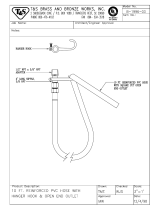
6) The wall mounting hook is used to secure the boiler to the shipping pallet. Remove this hook from the pallet and
secure to the wall using the 5/16” x 2” lag screws and washers, or other suitable anchors as appropriate (Figure
5.2). Make sure the hook is level.
 
8) If not already done in Step (5) locate and drill holes “C” and “D” using the obround slots in the bottom mounting

ure 5.2).
9) Verify that the front of the boiler is plumb. If it is not, install washers at holes “C” and “D” between the bottom




























9
Fi
gure 5.1 Wa
ll
Layout
/
Mount
i
ng Ho
l
e Locat
i
o
n
10
F
i
gure 5.2 Bo
il
er Mount
i
ng Brac
k
et Insta
ll
at
i
on
/
Bo
il
er Wa
ll
Mount
i
n
g
11
VI Air for Ventilation
Air for combustion must always be obtained directly from outdoors. See Section VII for intake piping. Adequate air for

-
tion manual or applicable code.





12
VII Venting
A. Vent System Design
There are two basic ways to vent this boiler:
 - Vent system exits the building through an outside wall. Combustion air


between the boiler and the terminal using separate pipes.
All of these systems are considered “direct vent” because the air for combustion is drawn directly from the outdoors into the


addition, observe the following guidelines:
1. Approved Vent Systems and Materials – The following materials and vent systems may be used to vent this boiler:
 
 

of foam core PVC is not permitted for venting. PVC vent pipe may not be used to vent this boiler in Canada.
 
 

 


 
 
 
 

 


 


 


 

 
 
 

 
13
Use PVC and/or CPVC for the air intake system. PVC may be used for all air intake piping between the intake terminal and
the boiler.
When CPVC and/or PVC pipe is used, it must be joined using primer and cement that is listed for use with the pipe material
being joined (PVC, CPVC, or CPVC to PVC).
2. Vent Components Supplied with this Boiler – This boiler is supplied with some of the components needed for 3” CPVC/PVC

locally. The CPVC Pipe and elbow supplied with this boiler are not listed to ULC S636 and may not be used in Canada.
3. Maximum Vent and Air Intake Lengths - The maximum length of the vent air intake piping depends upon the vent option
selected and the boiler size.
 for the maximum vent lengths. These maximum lengths apply to both the
vent and intake piping (e.g. Option 1 may have up to 60ft of intake and 60ft of vent piping). For all vent systems, the lengths

must be reduced by the amount shown in Table 


“long sweep” elbows are treated as having the same equivalent length.
Example:
A 3” twin pipe horizontal CPVC/PVC vent system is planned for a horizontally vented 120MBH model which has the
following components in the vent system:
 1 ft CPVC Straight Pipe
 90 CPVC Elbow (short bend)
 1-1/2 ft CPVC Straight Pipe
 Coupling
 10 ft PVC Straight Pipe
 90 PVC Elbow (Sanitary Elbow Design)
 15 ft PVC Straight Pipe
 PVC Coupling Terminal
The Vent Option #2 column in Table 7.1 describes a horizontal direct vent system using 3” CPVC and PVC pipe. From this

From Table 7.7, we see that the equivalent length of the 90 PVC elbow is 4ft and that the equivalent length of the coupling is
0ft. The total equivalent length of the planned venting system is therefore:

+ 4ft (PVC 90 Sanitary Elbow) + 15ft (Straight PVC) + 0ft (Coupling Terminal) = 31.5ft.
Since Table 7.1 shows a maximum allowable vent length of 135ft, the planned vent system length is acceptable.
4. Minimum Vent and Air Intake Lengths 
5. Permitted Terminals for Horizontal Venting:
Terminal Option A: Fittings (Acceptable for Vent Options 1-6) – Vent terminates in a plain end (coupling for PVC, bell end
for Polypro and plain end pipe for InnoFlue). Intake terminates in a PVC 90 sweep elbow pointing down. Outer edge of both

exposed to the outdoors must be UV resistant.





14

Vent Option 123456
Illustrated in Figure      
Pipe Penetration
through Structure
Vent Wall Wall Wall Wall Wall Wall
Intake Wall Wall Wall Wall Wall Wall
Material
Vent
CPVC/PVC
(Note 2)
CPVC/PVC
(Note 2)
Duravent
PolyPro
(Rigid)
Duravent
PolyPro
(Rigid)
Centrotherm
InnoFlue
SW
Centrotherm
InnoFlue
SW
Intake PVC PVC PVC PVC PVC PVC
Nominal Diameter
Vent 2” 3” 2” 3” 2” 3”
Intake 2” 3” 2” 3” 2” 3”
Min Equivalent Vent Length:
Models
080 12” 12” 12” 12” 12” 12”
100 12” 12” 12” 12” 12” 12”
120
Not
Permitted
12”
Not
Permitted
12”
Not
Permitted
12”
150 52” 52” 52”
180 52” 52” 52”
Max Equivalent Vent Length (Note 1):
Models
080 60ft 135ft 60ft 135ft 60ft 135ft
100 60ft 135ft 60ft 135ft 60ft 135ft
120
Not
Permitted
135ft
Not
Permitted
135ft
Not
Permitted
135ft
150 135ft 135ft 135ft
180 135ft 135ft 135ft
Terminal Option A
(Fittings)
Vent
Coupling w
Screen
(Note 3)
Coupling w
Screen
(Note 3)
Bell End w
Screen
Bell End w
Screen
ISEP02 or
ISEP0239
w Screen
ISEP03 or
ISEP0339
w Screen
Intake
Elbow w
Screen
(Note 3)
Elbow w
Screen
(Note 3)
Elbow w
Screen
Elbow w
Screen
Elbow w
Screen
Elbow w
Screen
Terminal Option B

Ipex #
196984
Ipex
#196985
Not
Permitted
Not
Permitted
Not
Permitted
Not
Permitted
Terminal Option C
(Ipex FGV Concentric)
Ipex 196105
(Note 4)
Ipex 196006
(Note 4)
Not
Permitted
Not
Permitted
Not
Permitted
Not
Permitted
Terminal Option D
(DuraVent Horizontal Concentric)
Not
Permitted
Not
Permitted
2PPS-HK 3PPS-HK
Not
Permitted
Not
Permitted
Notes:
1) Max vent lengths shown also apply to the intake. For example, Vent Option #1 may have up to 60ft of vent pipe and also up to
60 ft of intake pipe.
2) First 30” of vent and vent Elbow connected to boiler must be CPVC. Downstream vent pipe can be PVC except as noted in
text.

4) Ipex FGV Concentric Terminal available in various lengths and also CPVC. See text.
15
Use of rodent screens is generally recommended for both terminations. Two rodent screens suitable for 3” PVC terminals


Size/Vent System Rodent Screen (“Bird Guard”)
2” Polypro DuraVent # 2PPS-BG
3” Polypro DuraVent # 3PPS-BG
2” InnoFlue Centrotherm # IASPP02
3” InnoFlue Centrotherm # IASPP03






See Part VIIB of this manual and the Ipex instructions provided with the terminal, for installation details.
Terminal Option C: Ipex FGV Concentric Terminal (Acceptable for Vent Options 1,2)
and may be used with CPVC/PVC vent systems. This terminal is available in various lengths and in both PVC and CPVC.
Terminals acceptable for use with these vent options are as follows:
Ipex PN FGV Concentric Terminal Description
196005 2 x 16” PVC
196105 2 x 28” PVC
196125 2 x 40” PVC
196006 3 x 20” PVC
196106 3 x 32” PVC
196116 3 x 44” PVC
 
 
See Part VIIB of this manual and the Ipex instructions provided with the terminal, for installation details.
Terminal Option D: Duravent PolyPro Concentric Terminal (Acceptable for Vent Options 3,4) - This terminal is shown in

instructions provided with the terminal, for installation details.
6. Horizontal Vent and Air Intake Terminal Location - Observe the following limitations on the vent terminal location (also see

 Vent terminal must be at least 1 foot from any door, window, or gravity inlet into the building.
 When separate vent and intake terminals are used, maintain the correct clearance and orientation between the
terminals. The vent and air intake terminals must be at the same height and their center lines must be between 12 and
36 inches apart. Both terminals must be located on the same wall.
 The bottom of all terminals must be at least 12” above the normal snow line. In no case should they be less than 12”
above grade level.
 
 Do not install the vent terminal directly over windows or doors.
 The bottom of the vent terminal must be at least 3 feet above any forced air inlet located within 10 feet.
 USA Only: A clearance of at least 4 feet horizontally must be maintained between the vent terminal and gas meters,
electric meters, regulators, and relief equipment. Do not install vent terminal over this equipment. In Canada, refer
to B149.1 Installation Code for clearance to meters, regulators and relief equipment.
 Do not locate the vent terminal under decks or similar structures.
 
depth exceed 36”.
Where permitted by the authority having jurisdiction and local experience, the terminal may be located closer to
unventilated
details.
 Vent terminal must be at least 6 feet from an inside corner.
 

be moved or protected.
 Install the vent and air intake terminals on a wall away from the prevailing wind. Reliable operation of this boiler
cannot be guaranteed if these terminals are subjected to winds in excess of 40 mph.
 Air intake terminal must not terminate in areas that might contain combustion air contaminates, such as near
swimming pools. See WARNING on page 12.
16


(VENT OPTIONS #1 & 2, TERMINAL OPTION B)


(VENT OPTIONS #1 & 2, TERMINAL OPTION C)

(VENT OPTIONS #3, 4, 5 & 6, TERMINAL OPTION A)
18

(VENT OPTIONS #3 & 4, TERMINAL OPTION D)

CPVC/PVC FITTING  POLYPRO OR INNOFLUE
VENT FITTING

2” 90 ELBOW (“SANITARY BEND”) 2.6 2” 90 ELBOW 4.5
3” 90 ELBOW (“SANITARY BEND”) 4.0 3” 90 ELBOW 
2” 90 ELBOW (“SHORT BEND” ) 6.0 2” 45 ELBOW 2.5
3” 90 ELBOW (“SHORT BEND”) 10.0 3” 45 ELBOW 4.6
2” 45 ELBOW 1.5
3” 45 ELBOW 2.0
2” COUPLING 0.0
3” COUPLING 0.0

  • Page 1 1
  • Page 2 2
  • Page 3 3
  • Page 4 4
  • Page 5 5
  • Page 6 6
  • Page 7 7
  • Page 8 8
  • Page 9 9
  • Page 10 10
  • Page 11 11
  • Page 12 12
  • Page 13 13
  • Page 14 14
  • Page 15 15
  • Page 16 16
  • Page 17 17
  • Page 18 18
  • Page 19 19
  • Page 20 20
  • Page 21 21
  • Page 22 22
  • Page 23 23
  • Page 24 24
  • Page 25 25
  • Page 26 26
  • Page 27 27
  • Page 28 28
  • Page 29 29
  • Page 30 30
  • Page 31 31
  • Page 32 32
  • Page 33 33
  • Page 34 34
  • Page 35 35
  • Page 36 36
  • Page 37 37
  • Page 38 38
  • Page 39 39
  • Page 40 40
  • Page 41 41
  • Page 42 42
  • Page 43 43
  • Page 44 44
  • Page 45 45
  • Page 46 46
  • Page 47 47
  • Page 48 48
  • Page 49 49
  • Page 50 50
  • Page 51 51
  • Page 52 52
  • Page 53 53
  • Page 54 54
  • Page 55 55
  • Page 56 56
  • Page 57 57
  • Page 58 58
  • Page 59 59
  • Page 60 60
  • Page 61 61
  • Page 62 62
  • Page 63 63
  • Page 64 64
  • Page 65 65
  • Page 66 66
  • Page 67 67
  • Page 68 68
  • Page 69 69
  • Page 70 70
  • Page 71 71
  • Page 72 72
  • Page 73 73
  • Page 74 74
  • Page 75 75
  • Page 76 76
  • Page 77 77
  • Page 78 78
  • Page 79 79
  • Page 80 80
  • Page 81 81
  • Page 82 82
  • Page 83 83
  • Page 84 84
  • Page 85 85
  • Page 86 86
  • Page 87 87
  • Page 88 88
  • Page 89 89
  • Page 90 90
  • Page 91 91
  • Page 92 92
  • Page 93 93
  • Page 94 94
  • Page 95 95
  • Page 96 96
  • Page 97 97
  • Page 98 98
  • Page 99 99
  • Page 100 100
  • Page 101 101
  • Page 102 102
  • Page 103 103
  • Page 104 104
  • Page 105 105
  • Page 106 106
  • Page 107 107
  • Page 108 108
  • Page 109 109
  • Page 110 110
  • Page 111 111
  • Page 112 112
  • Page 113 113
  • Page 114 114
  • Page 115 115
  • Page 116 116
  • Page 117 117
  • Page 118 118
  • Page 119 119
  • Page 120 120
  • Page 121 121
  • Page 122 122
  • Page 123 123
  • Page 124 124
  • Page 125 125
  • Page 126 126
  • Page 127 127
  • Page 128 128

Crown Boiler PHNTM100HNT1SU Installation guide

Type
Installation guide
This manual is also suitable for

Ask a question and I''ll find the answer in the document

Finding information in a document is now easier with AI