Extron electronic MAV User manual
- Category
- Video switches
- Type
- User manual
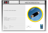
This manual is also suitable for

MAV Series
Matrix Switchers
68-353-04 Rev. C
Printed in the USA
01 04

This symbol is intended to alert the user of important operating and maintenance
(servicing) instructions in the literature provided with the equipment.
This symbol is intended to alert the user of the presence of uninsulated dangerous
voltage within the product's enclosure that may present a risk of electric shock.
Caution
Read Instructions • Read and understand all safety and operating instructions before using the
equipment.
Retain Instructions • The safety instructions should be kept for future reference.
Follow Warnings • Follow all warnings and instructions marked on the equipment or in the user
information.
Avoid Attachments • Do not use tools or attachments that are not recommended by the equipment
manufacturer because they may be hazardous.
Warning
Power sources • This equipment should be operated only from the power source indicated on the
product. This equipment is intended to be used with a main power system with a grounded
(neutral) conductor. The third (grounding) pin is a safety feature, do not attempt to bypass or
disable it.
Power disconnection • To remove power from the equipment safely, remove all power cords from
the rear of the equipment, or the desktop power module (if detachable), or from the power
source receptacle (wall plug).
Power cord protection • Power cords should be routed so that they are not likely to be stepped on or
pinched by items placed upon or against them.
Servicing • Refer all servicing to qualified service personnel. There are no user-serviceable parts
inside. To prevent the risk of shock, do not attempt to service this equipment yourself because
opening or removing covers may expose you to dangerous voltage or other hazards.
Slots and openings • If the equipment has slots or holes in the enclosure, these are provided to
prevent overheating of sensitive components inside. These openings must never be blocked by
other objects.
Lithium battery • There is a danger of explosion if battery is incorrectly replaced. Replace it only
with the same or equivalent type recommended by the manufacturer. Dispose of used batteries
according to the manufacturer's instructions.
Ce symbole sert à avertir l’utilisateur que la documentation fournie avec le matériel
contient des instructions importantes concernant l’exploitation et la maintenance
(réparation).
Ce symbole sert à avertir l’utilisateur de la présence dans le boîtier de l’appareil de
tensions dangereuses non isolées posant des risques d’électrocution.
Attention
Lire les instructions• Prendre connaissance de toutes les consignes de sécurité et d’exploitation avant
d’utiliser le matériel.
Conserver les instructions• Ranger les consignes de sécurité afin de pouvoir les consulter à l’avenir.
Respecter les avertissements • Observer tous les avertissements et consignes marqués sur le matériel ou
présentés dans la documentation utilisateur.
Eviter les pièces de fixation • Ne pas utiliser de pièces de fixation ni d’outils non recommandés par le
fabricant du matériel car cela risquerait de poser certains dangers.
Avertissement
Alimentations• Ne faire fonctionner ce matériel qu’avec la source d’alimentation indiquée sur
l’appareil. Ce matériel doit être utilisé avec une alimentation principale comportant un fil de
terre (neutre). Le troisième contact (de mise à la terre) constitue un dispositif de sécurité :
n’essayez pas de la contourner ni de la désactiver.
Déconnexion de l’alimentation• Pour mettre le matériel hors tension sans danger, déconnectez tous
les cordons d’alimentation de l’arrière de l’appareil ou du module d’alimentation de bureau (s’il
est amovible) ou encore de la prise secteur.
Protection du cordon d’alimentation • Acheminer les cordons d’alimentation de manière à ce que
personne ne risque de marcher dessus et à ce qu’ils ne soient pas écrasés ou pincés par des
objets.
Réparation-maintenance • Faire exécuter toutes les interventions de réparation-maintenance par un
technicien qualifié. Aucun des éléments internes ne peut être réparé par l’utilisateur. Afin
d’éviter tout danger d’électrocution, l’utilisateur ne doit pas essayer de procéder lui-même à ces
opérations car l’ouverture ou le retrait des couvercles risquent de l’exposer à de hautes tensions
et autres dangers.
Fentes et orifices • Si le boîtier de l’appareil comporte des fentes ou des orifices, ceux-ci servent à
empêcher les composants internes sensibles de surchauffer. Ces ouvertures ne doivent jamais
être bloquées par des objets.
Lithium Batterie • Il a danger d'explosion s'll y a remplacment incorrect de la batterie. Remplacer
uniquement avec une batterie du meme type ou d'un ype equivalent recommande par le
constructeur. Mettre au reut les batteries usagees conformement aux instructions du fabricant.
Safety Instructions • English
Consignes de Sécurité • Français
Sicherheitsanleitungen • Deutsch
Dieses Symbol soll dem Benutzer in der im Lieferumfang enthaltenen
Dokumentation besonders wichtige Hinweise zur Bedienung und Wartung
(Instandhaltung) geben.
Dieses Symbol soll den Benutzer darauf aufmerksam machen, daß im Inneren des
Gehäuses dieses Produktes gefährliche Spannungen, die nicht isoliert sind und
die einen elektrischen Schock verursachen können, herrschen.
Achtung
Lesen der Anleitungen • Bevor Sie das Gerät zum ersten Mal verwenden, sollten Sie alle Sicherheits-und
Bedienungsanleitungen genau durchlesen und verstehen.
Aufbewahren der Anleitungen • Die Hinweise zur elektrischen Sicherheit des Produktes sollten Sie
aufbewahren, damit Sie im Bedarfsfall darauf zurückgreifen können.
Befolgen der Warnhinweise • Befolgen Sie alle Warnhinweise und Anleitungen auf dem Gerät oder in
der Benutzerdokumentation.
Keine Zusatzgeräte • Verwenden Sie keine Werkzeuge oder Zusatzgeräte, die nicht ausdrücklich vom
Hersteller empfohlen wurden, da diese eine Gefahrenquelle darstellen können.
Vorsicht
Stromquellen • Dieses Gerät sollte nur über die auf dem Produkt angegebene Stromquelle betrieben
werden. Dieses Gerät wurde für eine Verwendung mit einer Hauptstromleitung mit einem
geerdeten (neutralen) Leiter konzipiert. Der dritte Kontakt ist für einen Erdanschluß, und stellt
eine Sicherheitsfunktion dar. Diese sollte nicht umgangen oder außer Betrieb gesetzt werden.
Stromunterbrechung • Um das Gerät auf sichere Weise vom Netz zu trennen, sollten Sie alle
Netzkabel aus der Rückseite des Gerätes, aus der externen Stomversorgung (falls dies möglich
ist) oder aus der Wandsteckdose ziehen.
Schutz des Netzkabels • Netzkabel sollten stets so verlegt werden, daß sie nicht im Weg liegen und
niemand darauf treten kann oder Objekte darauf- oder unmittelbar dagegengestellt werden
können.
Wartung • Alle Wartungsmaßnahmen sollten nur von qualifiziertem Servicepersonal durchgeführt
werden. Die internen Komponenten des Gerätes sind wartungsfrei. Zur Vermeidung eines
elektrischen Schocks versuchen Sie in keinem Fall, dieses Gerät selbst öffnen, da beim Entfernen
der Abdeckungen die Gefahr eines elektrischen Schlags und/oder andere Gefahren bestehen.
Schlitze und Öffnungen • Wenn das Gerät Schlitze oder Löcher im Gehäuse aufweist, dienen diese
zur Vermeidung einer Überhitzung der empfindlichen Teile im Inneren. Diese Öffnungen dürfen
niemals von anderen Objekten blockiert werden.
Litium-Batterie • Explosionsgefahr, falls die Batterie nicht richtig ersetzt wird. Ersetzen Sie
verbrauchte Batterien nur durch den gleichen oder einen vergleichbaren Batterietyp, der auch
vom Hersteller empfohlen wird. Entsorgen Sie verbrauchte Batterien bitte gemäß den
Herstelleranweisungen.
Este símbolo se utiliza para advertir al usuario sobre instrucciones importantes de
operación y mantenimiento (o cambio de partes) que se desean destacar en el
contenido de la documentación suministrada con los equipos.
Este símbolo se utiliza para advertir al usuario sobre la presencia de elementos con
voltaje peligroso sin protección aislante, que puedan encontrarse dentro de la caja
o alojamiento del producto, y que puedan representar riesgo de electrocución.
Precaucion
Leer las instrucciones • Leer y analizar todas las instrucciones de operación y seguridad, antes de usar
el equipo.
Conservar las instrucciones • Conservar las instrucciones de seguridad para futura consulta.
Obedecer las advertencias • Todas las advertencias e instrucciones marcadas en el equipo o en la
documentación del usuario, deben ser obedecidas.
Evitar el uso de accesorios • No usar herramientas o accesorios que no sean especificamente
recomendados por el fabricante, ya que podrian implicar riesgos.
Advertencia
Alimentación eléctrica • Este equipo debe conectarse únicamente a la fuente/tipo de alimentación
eléctrica indicada en el mismo. La alimentación eléctrica de este equipo debe provenir de un
sistema de distribución general con conductor neutro a tierra. La tercera pata (puesta a tierra) es
una medida de seguridad, no puentearia ni eliminaria.
Desconexión de alimentación eléctrica • Para desconectar con seguridad la acometida de
alimentación eléctrica al equipo, desenchufar todos los cables de alimentación en el panel trasero
del equipo, o desenchufar el módulo de alimentación (si fuera independiente), o desenchufar el
cable del receptáculo de la pared.
Protección del cables de alimentación • Los cables de alimentación eléctrica se deben instalar en
lugares donde no sean pisados ni apretados por objetos que se puedan apoyar sobre ellos.
Reparaciones/mantenimiento • Solicitar siempre los servicios técnicos de personal calificado. En el
interior no hay partes a las que el usuario deba acceder. Para evitar riesgo de electrocución, no
intentar personalmente la reparación/mantenimiento de este equipo, ya que al abrir o extraer las
tapas puede quedar expuesto a voltajes peligrosos u otros riesgos.
Ranuras y aberturas • Si el equipo posee ranuras o orificios en su caja/alojamiento, es para evitar el
sobrecalientamiento de componentes internos sensibles. Estas aberturas nunca se deben obstruir
con otros objetos.
Batería de litio • Existe riesgo de explosión si esta batería se coloca en la posición incorrecta. Cambiar
esta batería únicamente con el mismo tipo (o su equivalente) recomendado por el fabricante.
Desachar las baterías usadas siguiendo las instrucciones del fabricante.
Instrucciones de seguridad • Español
Precautions

QS-1
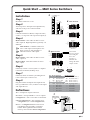
Quick Start — MAV Series Switchers
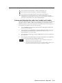
Installation
Step 1
Mount the switcher in a rack.
Step 2
Turn off power to the input and output devices,
and remove the power cords from them.
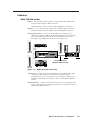
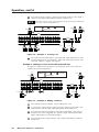
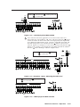
Step 3
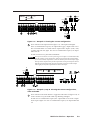
Cable the switcher for HDTV/component video ,
S-video, or composite video input and output (3).
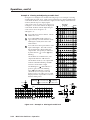
Step 4
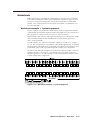
MAV 168/1616: Cable audio models for stereo
audio input (4). High impedance is generally over
800 ohms.
MAV 128 RCA: Cable the switcher for
stereo audio input. Each input has two
RCA connectors (left and right) for
unbalanced stereo audio input.
Step 5
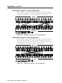
MAV 168/1616: Cable audio models for stereo
audio output (5).
MAV 128 RCA: Cable the switcher for stereo
audio output.
Step 6
If desired, connect a control system or computer
to the Remote RS-232/RS-422 port (6).
Step 7
If desired, attach an external sync timing device
to the external sync connectors (7).
Step 8
Plug the switcher and input and output devices
into a grounded AC source, and turn on the input
and output devices.
Definitions
Tie — An input-to-output connection.
Set of ties — An input tied to 2 or more outputs.
Configuration — One or more ties or sets of ties.
Current configuration — The currently active
configuration (also called configuration 0).
Preset — A configuration that has been stored.
One preset can be assigned to each input
button. When a preset is retrieved from
memory, it becomes the current configuration.
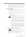
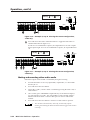
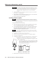
Unbalanced Input
Tip
Sleeve
Tip
Sleeve
Balanced Input
Tip
Ring
Sleeve (s)
Tip
Ring
Tip
Ring
Sleeve (s)
Tip
Ring
Balanced Input
(high impedance)
(high impedance)
(600 ohms)
600 ohms
600 ohms
4 MAV 168/1616
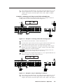
Unbalanced Output
Tip
See warning
Sleeve
Tip
See warning
Balanced Output
Tip
Ring
Sleeve (s)
Tip
Ring
5 MAV 168/1616
Input 1
Output 1
Input 1
Output 1
Y
R-Y
B-Y
Y
C
Component HDTV video
S-video
Input 1
Output 1
MAV 168/1616
1
2
1
2
1
2
1
2
1
2
1
2
3
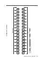
6
Female
51
96
Male
15
69
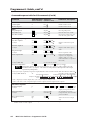
niP 232-SR noitcnuF 224-SR noitcnuF
1 — desutoN+XT)+(atadtimsnarT
2XTatadtimsnarT-XT)-(atadtimsnarT
3XRatadevieceR-XR)-(atadevieceR
4 — desutoN+XR)+(atadevieceR
5 dnG dnuorglangiS dnG dnuorglangiS
6 — desutoN — desutoN
7 — desutoN — desutoN
8 — desutoN — desutoN
9 — desutoN — desutoN
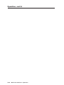
7
Timing source MAV switcher
OUT
To next device
CAUTION
Connect the
sleeve to ground.
Connecting the
sleeve to a
negative (-)
terminal will
damage the audio
output circuits.

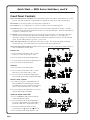
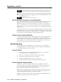
Quick Start — MAV Series Switchers, cont’d
QS-2
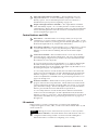
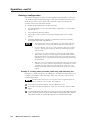
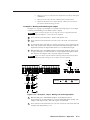
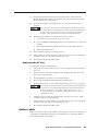
Front Panel Controls
Input and output buttons and LEDs select and identify inputs and outputs. Input buttons also select
presets. On audio models, the output LEDs also display the audio level of the selected input.
Enter button saves changes when you change the configuration.
Preset button saves a configuration as a preset or recalls a previously-defined preset.
View button selects a view-only mode that prevents inadvertent configuration changes. On audio
models, the View button decrements the audio level of the selected input. The View LED indicates
a negative (-) attenuation value.
Esc button cancels selections in progress and resets the front panel LEDs. The Esc button does not
reset the current configuration, the Video and Audio LEDs, any presets, or any audio gain/
attenuation settings. On audio models, the Esc button increments the audio level of the selected
input. The Esc LED indicates a positive (+) gain value.
Video and Audio buttons select/deselect video and/or audio. The Audio LED blinks to indicate
audio breakaway. The Audio button also selects the audio level/adjust mode.
Input and output label windows hold labels that can be created easily with Extron’s label software or
with any Brother P-Touch labeler.
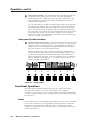
Create a tie
A. Press and release the Video and/or Audio
button(s) to select audio and/or video.
B. Press and release the desired input button.
C. Press and release the desired output button(s).
D. Press and release the Enter button.
View ties
A. Press and release the View button.
B. Press and release the Video and/or Audio
button(s) to select audio and/or video.
C. Press and release the desired input button.
The selected input and tied output LEDs light.
Save or recall a preset
A. To save a preset, press and hold the Preset
button until the Preset LED begins to blink.
To recall a preset, press and release the Preset
button. The Preset LED turns on steadily.
B. Press and release the input button associated
with the desired preset number.
View and adjust audio level
A. Press and hold the Audio button until the
Audio LED begins to blink.
B. Press and release the desired input button.
The level is displayed by the output LEDs, (+)
by the Esc LED, and (-) by the View LED.
C. Increment and decrement the level by
pressing the Esc (
) and View ( ) buttons.
D. Press and release the Audio button to exit.
3
3
4
4
5
6
ENTER
6
7
7
8
PRESET VIEW ESC VIDEO AUDIO
VIDEO AUDIO
8
CONTROL I/O
A
C
D
B
B BB
C
3
3
4
4
5
6
ENTER
6
7
7
8
PRESET VIEW ESC VIDEO AUDIO
VIDEO AUDIO
8
CONTROL I/O
B
A
C
3 4 6
ENTER
7 8
PRESET VIEW ESC
CONTROL
A
Save
Recall
B
B
B
B
1
1
2
2
3
4
ENTER
4
5
5
6
PRESET VIEW ESC VIDEO AUDIO
AUDIO
6
CONTROL I/O
A
D
B
45
VIEW ESC
C
B
BB
B
LED key: = off, = on, = blinking,

i
MAV Series Switchers • Table of Contents
Table of Contents
Chapter 1 • Introduction ....................................................................................................... 1-1
Features ................................................................................................................................... 1-5
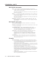
MAV 128 RCA model ......................................................................................................... 1-5
MAV 168/1616 video models ............................................................................................. 1-6
MAV 168/1616 audio models ............................................................................................ 1-6
All models ........................................................................................................................... 1-6
Chapter 2 • Installation .......................................................................................................... 2-1
Installation Overview ....................................................................................................... 2-2
Mounting the Switcher .................................................................................................... 2-2
Cabling and Rear Panel Views ...................................................................................... 2-2
Power connection .............................................................................................................. 2-4
Video input and output connections (video models only) .............................................. 2-4
Audio input and output connections (audio models only) ............................................. 2-5
RS-232/422 connection ...................................................................................................... 2-6
External sync connection ................................................................................................... 2-6
Additional rear panel view ............................................................................................... 2-7
Chapter 3 • Operation ............................................................................................................. 3-1
Front Panel Controls and Indicators ......................................................................... 3-2
Definitions .......................................................................................................................... 3-2
Input buttons, output buttons, and LEDs ......................................................................... 3-2
Control buttons and LEDs ................................................................................................. 3-3
I/O controls ......................................................................................................................... 3-3
Front panel I/O Label windows ......................................................................................... 3-4
Front Panel Operations .................................................................................................... 3-4
Power ................................................................................................................................. 3-4
Creating a configuration ................................................................................................... 3-5
Example 1: Creating a set of video and audio ties ....................................................... 3-5
Example 2: Adding a tie to a set of video and audio ties ............................................ 3-6
Example 3: Removing a tie from a set of video and audio ties .................................... 3-7
Viewing a configuration ................................................................................................... 3-8
Example 4: Viewing video and audio, audio only, and video only ties ........................ 3-8
Muting and unmuting video and/or audio .................................................................... 3-10
Example 5: Muting and unmuting an output ............................................................ 3-11
Using presets .................................................................................................................... 3-12
Example 6: Saving a preset ........................................................................................ 3-12
Example 7: Recalling a preset .................................................................................... 3-12
Viewing and adjusting the audio level (models with audio) ........................................ 3-13
Example 8: Viewing and adjusting an audio level ..................................................... 3-14
Executive mode (front panel security lockout) .............................................................. 3-16
System reset to factory defaults ..................................................................................... 3-16
Troubleshooting ................................................................................................................ 3-16
General checks ................................................................................................................. 3-16
Plasma display S-video problem ...................................................................................... 3-16

ii MAV Series Switchers • Table of Contents
Table of Contents, cont’d
Worksheets .......................................................................................................................... 3-17
Worksheet example 1: System equipment .................................................................... 3-17
Worksheet example 2: Daily configuration ................................................................... 3-18
Worksheet example 3: Test configuration ..................................................................... 3-18
Configuration worksheet ................................................................................................ 3-19
Chapter 4 • Programmer’s Guide ..................................................................................... 4-1
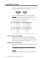
Host-to-Switcher Instructions....................................................................................... 4-2
Switcher-Initiated Messages ......................................................................................... 4-2
Switcher Error Responses ............................................................................................... 4-3
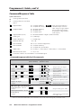
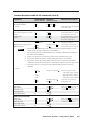
Using the Command/Response Table ........................................................................ 4-3
Command/Response Table .............................................................................................. 4-4
Chapter 5 • Matrix Software .............................................................................................. 5-1
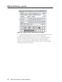
Matrix Switchers Control Program ............................................................................ 5-2
Installing the software ...................................................................................................... 5-2
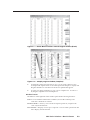
Using the software ............................................................................................................ 5-2
Overview ...................................................................................................................... 5-2
Using emulation mode ................................................................................................. 5-5
Using the help system ................................................................................................... 5-5
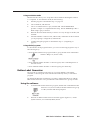
Button-Label Generator ................................................................................................... 5-5
Using the software ............................................................................................................ 5-5
Appendix A • Specifications .............................................................................................. A-1
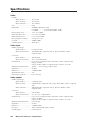
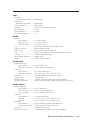
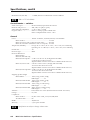
Specifications....................................................................................................................... A-2
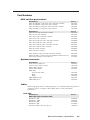
Part Numbers ....................................................................................................................... A-5
MAV switcher part numbers ............................................................................................ A-5
Optional accessories ......................................................................................................... A-5
Cables ................................................................................................................................ A-5
Bulk cable .................................................................................................................... A-5
Assorted connectors .................................................................................................... A-6
Pre-cut cables .............................................................................................................. A-6

iiiMAV Series Switchers • Table of Contents
Appendix B • Reference Information ...........................................................................B-1
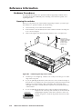
Hardware Procedures ........................................................................................................ B-2
Opening the switcher ........................................................................................................ B-2
Closing the switcher .......................................................................................................... B-3
Swapping the serial ports .................................................................................................. B-3
Installing a firmware update ............................................................................................ B-4
Replacing the AC fuse ....................................................................................................... B-5
Button Labels ........................................................................................................................ B-5

iv MAV Series Switchers • Table of Contents
Table of Contents, cont’d
68-353-04 Rev. C
Printed in the USA
01 04
All trademarks mentioned in this manual are the properties of their respective owners.

MAV Series Switchers
1
Chapter One
Introduction
Features

Introduction, cont’d
MAV Series Switchers • Introduction1-2
Introduction
The Extron MAV Series switchers are broadcast quality matrix switchers that
distribute any video and/or audio input to any combination of outputs. The MAV
switchers can route multiple input/output configurations simultaneously. There
are four matrix sizes available, each with unique features or optional capabilities:
• MAV 84 RCA (eight inputs by four outputs)
• MAV 128 RCA (twelve inputs by eight outputs)
• MAV 168 (sixteen inputs by eight outputs)
• MAV 1616 (sixteen inputs by sixteen outputs)
The MAV 84 and MAV 128 input and output audio on RCA connectors.
Audio models in the MAV 168 and MAV 1616 series input and output audio on
3.5 mm, 5-pole captive screw terminals. The MAV 168 and MAV 1616 are available
in models that can switch three video planes (component video), two video planes
(S-video), or one video plane (composite) video, each with or without an audio
plane. An audio-only matrix switcher is also available in the MAV 168 and
MAV 1616 series.
MAV component video switchers can also route RGsB and RsGsBs video signals.
Switchers configured for component video can also route multiple composite video
planes or S-video and composite video. If used in this way, the various planes
cannot be broken away; all inputs must be routed to the same outputs.
MAV S-video switchers can also be used to switch two planes of composite video.
If used in this way, the two planes cannot be broken away; both inputs must be
routed to the same outputs.
For the models with audio, audio switching can either be linked with the video
(audio follow) or be independent of the video (audio breakaway). Adjustable
audio gain and attenuation compensates for level differences between audio
inputs.
The MAV Series switchers are single-box solutions to simple 150 MHz (-3dB)
routing applications (figure 1-1, figure 1-2, figure 1-3, and figure 1-4). Each input
and output is individually isolated and buffered, and any inputs can be switched to
any one or all outputs with virtually no crosstalk or signal noise between channels.

1-3MAV Series Switchers • Introduction
DVD Player
16 Inputs - 16 Outputs
Monitor
MAV 1616 Component
Figure 1-1 — Typical MAV 1616 component matrix switcher application
DVD Player
Monitor
16 Inputs - 16 Outputs
MAV 1616 S-video
Figure 1-2 — Typical MAV 1616 S-video matrix switcher application

Introduction, cont’d
MAV Series Switchers • Introduction1-4
DVD Players
Stereo
Audio
VCR VCR Laserdisc Player
Security
Cameras
Video Camera
CRT
Projector
CRT
Projector
Monitor
Monitor
LCD
Projector
VCR
MAV 1616
Series Switcher
RS-232 Control
Figure 1-3 — Typical MAV 1616 composite matrix switcher application
DVD players
Stereo audio
VCR
Laserdisc player
Video cameras
CRT
projectors
Monitor
LCD
projector
VCR
MAV 128 RCA
RS-232 control
Figure 1-4 — Typical MAV 128 RCA application
The MAV component video switchers are housed in a 4U high enclosure. MAV
S-video switchers are in a 3U enclosure. MAV composite and audio-only switchers
are in a 2U enclosure. The appropriate rack mount kit is included with each
switcher. Each model has an internal 100VAC to 240VAC, 50/60 Hz, 15 watts
(MAV 128 RCA) or 20 watts (MAV 168/1616 series), auto-switchable power supply
that provides worldwide power compatibility.

1-5MAV Series Switchers • Introduction
Features
MAV 128 RCA model
Inputs — These switchers offer 12 NTSC 3.58, NTSC 4.43, PAL, and SECAM
composite video inputs on BNC connectors.
Unbalanced stereo audio is input on left and right RCA connectors.
Outputs — 4 or 8 composite video outputs are available on BNC connectors.
Unbalanced stereo audio is output on left and right RCA connectors.
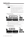
Audio gain/attenuation — Users can set the input level of audio gain or
attenuation (-15dB to +9dB) via the RS-232/RS-422 link or from the front
panel. Individual input audio levels can be adjusted so there are no
noticeable volume differences between sources (figure 1-5).
Audio
inputs
Audio
inputs
VCR
No noticeable volume
differences between sources
Audio system
CD jukebox
MAV Series switcher
I/OCONTROL
MAV SERIES SWITCHER
VIDEO
0
-3
-6
-9
-12
-15
Low audio
output level
3
6
9
12
15
+4
+1
-2
-5
-8
-12
+7
+10
+13
+16
+19
VUdBu
0
-3
-6
-9
-12
-15
Output
level
3
6
9
12
15
+4
+1
-2
-5
-8
-12
+7
+10
+13
+16
+19
VUdBu
0
-3
-6
-9
-12
-15
High audio
output level
3
6
9
12
15
+4
+1
-2
-5
-8
-12
+7
+10
+13
+16
+19
VUdBu
Figure 1-5 — Audio gain and attenuation
Audio follow — Audio can be switched with the corresponding video input,
allowing any audio signal to be selected with any video signal
simultaneously to one or all outputs in any combination. Audio follow
switching can be done via front panel control or under RS-232/RS-422
remote.
Audio breakaway — Audio can be broken away from its corresponding video
signal. Audio breakaway switching can be done via front panel control or
under RS-232/RS-422 control.

Introduction, cont’d
MAV Series Switchers • Introduction1-6
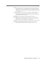
MAV 168/1616 video models
Inputs — These switchers offer 16 RGsB, RsGsBs, HDTV, component video,
S-video, or NTSC 3.58, NTSC 4.43, PAL, and SECAM composite video inputs
on BNC connectors (video models).
Stereo audio can be balanced or unbalanced, on 3.5 mm, 5-pole captive screw
terminals (audio models).
Outputs — 8 or 16 RGsB, RsGsBs, HDTV, component video, S-video, or NTSC 3.58,
NTSC 4.43, PAL, and SECAM composite video outputs are available on BNC
connectors (video models).
Stereo audio can be balanced or unbalanced, on 3.5 mm, 5-pole captive screw
terminals (audio models).
Bandwidth — Bandwidth is a maximum of 150 MHz (-3dB), fully loaded. This
high bandwidth allows the MAV switchers to switch everything from NTSC
video to HDTV.
MAV 168/1616 audio models
Inputs — 16 stereo audio inputs, balanced or unbalanced, on 3.5 mm, 5-pole
captive screw terminals.
Outputs — 8 or 16 stereo audio outputs, balanced or unbalanced, on 3.5 mm, 5-pole
captive screw terminals.
Audio gain/attenuation — Users can set the input level of audio gain or
attenuation (-15dB to +9dB) via the RS-232/RS-422 link or from the front
panel. Individual input audio levels can be adjusted so there are no
noticeable volume differences between sources (figure 1-5).
Audio follow — Audio can be switched with the corresponding video input,
allowing any audio signal to be selected with any video signal
simultaneously to one or all outputs in any combination. Audio follow
switching can be done via front panel control or under RS-232/RS-422
remote.
Audio breakaway — Audio can be broken away from its corresponding video
signal. Audio breakaway switching can be done via front panel control or
under RS-232/RS-422 control.
All models
Operational flexibility — Operations such as input/output selection, setting of
presets, and adjustment of audio levels can be performed on the front panel
or over the RS-232/RS-422 link. The RS-232/RS-422 link allows remote
control via a PC or control system.
• QuickSwitch Front Panel Controller (QS-FPC™) — The MAV series QS-FPC
feature supports touch-of-a-button input and output selection, preset creation
and selection, and audio gain and attenuation control.
• Windows-based control program — Extron’s Windows-based control
program provides a versatile range of operational options with its graphical
interface and drag-and-drop/point-and-click operation. The Windows-based
control program also has an emulation mode that lets you create a switcher
configuration file at the home office and then download it for use by the
switcher on site.
• Simple Instruction Set (SIS™) — The remote control protocol uses Extron’s
SIS for easy programming and operation.

1-7MAV Series Switchers • Introduction
Labeling — Extron’s label software ships with every Extron matrix switcher. You
can create labels to place alongside the front panel I/O buttons, with names,
alphanumeric characters, or color bitmaps for easy and intuitive input and
output selection. Alternatively, labels can be made with any Brother P-Touch
or comparable labeler.
Global memory presets — 12 (MAV 128) or 16 (MAV 168 and MAV 1616) global
memory presets are a time-saving feature that lets you set up and store
input/output configurations in advance and then recall those configurations
when needed with a few simple steps.
Rack mount — Rack mountable in any conventional 19” wide rack.
Power supply — Includes an internal 100VAC to 240VAC, 50/60 Hz, 15 watts
(MAV 128 RCA) or 20 watts (MAV 168/1616 Series), auto-switchable power
supply, which provides worldwide power compatibility.
Switching — Provides individually buffered, independent matrix switched outputs.
External sync input and output connectors — Allow the switcher to use an
external signal to synchronize switching during the vertical interval.

Introduction, cont’d
MAV Series Switchers • Introduction1-8

MAV Series Switchers
2
Chapter Two
Installation
Installation Overview
Mounting the Switcher
Cabling and Rear Panel Views

Installation, cont’d
MAV Series Switchers • Installation2-2
Installation
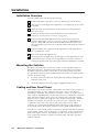
Installation Overview
To install a MAV Series switcher, do the following:
1
If desired, mount the switcher in a rack (see Mounting the switcher below).
2
Turn off power to the input and output devices, and unplug the power cables
from them.
3
Attach the input and output devices to the switcher (see Cabling and Rear
Panel Views below).
4
If desired, attach an external sync timing device to the external sync
connectors (see External sync connection on page 2-6).
5
If desired, attach an MCP 1000 remote control panel master unit to the
switcher’s RS-232/422 connector. You can also attach an MKP 1000 remote
keypad or MCP 1000 slave unit to the MCP 1000 master unit. Refer to the
MCP 1000 Remote Control Panel User’s Manual and the MKP 1000 User’s Manual
for details.
6
Plug the switcher and, if appropriate, the input devices and output devices
into a grounded AC source.
7
Turn on the input and output devices.
8
The image from each input device should appear on the output devices, and
you should be able to switch from one input device to another. If this does
not happen, double check steps 3 through 5 and make adjustments as needed.
Mounting the Switcher
The MAV component video models are housed in rack-mountable, 4U high, 17”
wide metal enclosures. The MAV S-video models are housed in 3U enclosures.
The MAV composite and audio-only models are housed in 2U high, enclosures.
The appropriate rack mount kit is included with each switcher. To rack mount the
switcher, do the following:
1. Insert the switcher into the rack, aligning the holes in the mounting bracket
with those in the rack.
2. Secure the switcher to the rack using the supplied machine screws.
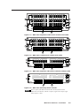
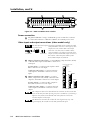
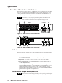
Cabling and Rear Panel Views
All connectors are on the rear panel. The switcher can connect to up to as many as
16 component video, S-video, composite video and/or stereo audio devices,
depending on the model. The switcher can output to as many as 16 video and/or
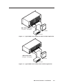
audio outputs, depending on the model. Figure 2-1 shows a MAV 1616 component
video and audio switcher. Figure 2-2 shows a MAV S-video and audio switcher.
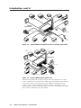
Figure 2-3 shows a MAV 1616 composite video switcher without audio. MAV 168
switchers are housed in the same 2U, 3U, or 4U enclosures as their MAV 1616
counterparts of the same video and/or audio type, but have fewer output
connectors to accommodate the different matrix sizes they provide. Figure 2-4
shows a MAV 1616 audio switcher. Figure 2-5 shows a MAV 128 RCA switcher.
Some devices, such as VCRs, can be connected to both input and output connectors
of the switcher. Others, such as tape players or CD players, can be connected only
to the audio input connectors. An audio device and a separate video device can
share an input; the switcher is capable of switching video and audio separately
(audio breakaway).

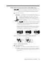
2-3MAV Series Switchers • Installation
R-Y INPUTS
Y INPUTS
B-Y INPUTS
R-Y OUTPUTS
Y OUTPUTS
B-Y OUTPUTS
7 9 11 13 15
81012
135
246 1416
7 9 11 13 15
81012
135
246 1416
7 9 11 13 15
81012
135
246 1416
7 9 11 13 15
81012
135
246 1416
7 9 11 13 15
81012
135
246 1416
7 9 11 13 15
81012
135
246 1416
1
6
7
2
3
54
Figure 2-1 — MAV 1616 component video matrix switcher with audio
7
Y INPUTS
C INPUTS
Y OUTPUTS
C OUTPUTS
9 111315
81012
135
246 1416
7 9 11 13 15
81012
135
246 1416
7 9 11 13 15
81012
135
246 1416
7 9 11 13 15
81012
135
246 1416
54
1
6
7
2
3
Figure 2-2 — MAV 1616 S-video matrix switcher with audio
1.2A MAX
100-240 VAC 50/60 Hz
ANAHEIM, CA
INPUTS
INPUTS
OUTPUTS
INPUTS
OUTPUTS
OUT
IN
EXT
SYNC
REMOTE
RS232/
RS422
13579111315
2 4 6 8 10 12 14 16
13579111315
2 4 6 8 10 12 14 16
12 34 5678 9101112
13 14 15 16
OUTPUTS
1
6
7
2
3
54
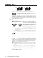
Figure 2-3 — MAV 1616 composite video matrix switcher without audio
1.2A MAX
100-240 VAC 50/60 Hz
ANAHEIM, CA
INPUTS
INPUTS
OUTPUTS
INPUTS
OUTPUTS
OUT
IN
EXT
SYNC
REMOTE
RS232/
RS422
13579111315
2 4 6 8 10 12 14 16
13579111315
2 4 6 8 10 12 14 16
12 34 5678 9101112
13 14 15 16
OUTPUTS
1
6
7
54
Figure 2-4 — MAV 1616 audio-only matrix switcher
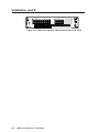
The rear panel of the MAV 168 models have the same features as the
MAV 1616 series models, with the exception of eight video outputs, eight
audio outputs, or both.

Installation, cont’d
MAV Series Switchers • Installation2-4
1
6
54
2 3
7
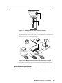
Figure 2-5 — MAV 128 RCA matrix switcher
Power connection
1
AC power connector — Plug a standard IEC power cord into this connector
to connect the switcher to a 100VAC to 240VAC, 50 or 60 Hz power source.
Video input and output connections (video models only)
All video input and output connections to the MAV Series switchers are made
with female BNC connectors. Some types of video
output devices do not have BNC video output
connectors. For these cases, a suitable cable or
connector adapter is necessary between the device
output connector and the BNC input connector of
the switcher. The Extron part number for the
RCA-to-BNC adapter is 10-264-01.
2
HDTV/component video inputs — Connect HDTV, component video, RGsB,
or RsGsBs video inputs to these BNC connectors for
each input.
S-video inputs — Connect S-video inputs to these
BNC connectors for each input.
Composite video inputs — Connect composite
video inputs to these BNC connectors for each
input.
3
HDTV/component video outputs — Connect
HDTV, component video, RGsB, or RsGsBs video
outputs to these BNC connectors for each output.
S-video outputs — Connect S-video outputs to
these BNC connectors for each output.
Composite video outputs — Connect composite
video outputs to these BNC connectors for each
output.
The component video and S-video MAV Series switchers can also switch video
lower on the video food chain by using only two or one BNC(s). If switching a
different video format, ensure that the same video planes are used on the
switcher output as on the input.
The MAV Series Switchers do not alter the video signal in any way. The
signal output by the switcher is in the same format as the input.
BNC ConnectorRCA Connector
RCA-to-BNC Connector
Input 1
Output 1
Input 1
Output 1
Y
R-Y
B-Y
Y
C
Component HDTV video
S-video
Input 1
Output 1
MAV 168/1616
1
2
1
2
1
2
1
2
1
2
1
2
Page is loading ...
Page is loading ...
Page is loading ...
Page is loading ...
Page is loading ...
Page is loading ...
Page is loading ...
Page is loading ...
Page is loading ...
Page is loading ...
Page is loading ...
Page is loading ...
Page is loading ...
Page is loading ...
Page is loading ...
Page is loading ...
Page is loading ...
Page is loading ...
Page is loading ...
Page is loading ...
Page is loading ...
Page is loading ...
Page is loading ...
Page is loading ...
Page is loading ...
Page is loading ...
Page is loading ...
Page is loading ...
Page is loading ...
Page is loading ...
Page is loading ...
Page is loading ...
Page is loading ...
Page is loading ...
Page is loading ...
Page is loading ...
Page is loading ...
Page is loading ...
Page is loading ...
Page is loading ...
Page is loading ...
Page is loading ...
Page is loading ...
Page is loading ...
Page is loading ...
Page is loading ...
Page is loading ...
Page is loading ...
Page is loading ...
Page is loading ...
Page is loading ...
Page is loading ...
-
 1
1
-
 2
2
-
 3
3
-
 4
4
-
 5
5
-
 6
6
-
 7
7
-
 8
8
-
 9
9
-
 10
10
-
 11
11
-
 12
12
-
 13
13
-
 14
14
-
 15
15
-
 16
16
-
 17
17
-
 18
18
-
 19
19
-
 20
20
-
 21
21
-
 22
22
-
 23
23
-
 24
24
-
 25
25
-
 26
26
-
 27
27
-
 28
28
-
 29
29
-
 30
30
-
 31
31
-
 32
32
-
 33
33
-
 34
34
-
 35
35
-
 36
36
-
 37
37
-
 38
38
-
 39
39
-
 40
40
-
 41
41
-
 42
42
-
 43
43
-
 44
44
-
 45
45
-
 46
46
-
 47
47
-
 48
48
-
 49
49
-
 50
50
-
 51
51
-
 52
52
-
 53
53
-
 54
54
-
 55
55
-
 56
56
-
 57
57
-
 58
58
-
 59
59
-
 60
60
-
 61
61
-
 62
62
-
 63
63
-
 64
64
-
 65
65
-
 66
66
-
 67
67
-
 68
68
-
 69
69
-
 70
70
-
 71
71
-
 72
72


Extron electronic MAV User manual
- Category
- Video switches
- Type
- User manual
- This manual is also suitable for
Ask a question and I''ll find the answer in the document
Finding information in a document is now easier with AI
Related papers
-
Extron MAV AV Series User manual
-
 Extron electronics MAV Plus User manual
-
Extron electronic MAV 44 Series User manual
-
Extron electronics CrossPoint 450 Plus 4864 User manual
-
-
Extron CrossPoint 1616 Matrix Switcher User manual
-
-
Extron electronics 84 User manual
-
Extron electronics SW 12AV User manual
-
 Extron electronics RSB129 User manual


Other documents
-
Extron CrossPoint 450 Plus 64 Series User manual
-
 T'nB ADA22 Datasheet
-
Extron CrossPoint 450 Plus 64 Series User manual
-
-
 StarTech.com COMPAAHQ6 Datasheet
-
-
Altinex MX2436RM User manual
-
-
-
 Extron electronics MVX Plus 128 VGA A User manual


