Sophos APX 320X Operating Instructions Manual

Category
WLAN access points
Type
Operating Instructions Manual

This manual is also suitable for

Sophos APX 320X is a high-performance wireless access point featuring the latest 802.11ac Wave 2 technology for an exceptional user experience. Easily managed via Sophos Central, it offers seamless integration, allowing you to set up and manage your network from anywhere. With its dual-radio design, the APX 320X delivers up to 1.734 Gbps throughput, ensuring reliable and blazing-fast connectivity for your devices.

Sophos APX 320X is a high-performance wireless access point featuring the latest 802.11ac Wave 2 technology for an exceptional user experience. Easily managed via Sophos Central, it offers seamless integration, allowing you to set up and manage your network from anywhere. With its dual-radio design, the APX 320X delivers up to 1.734 Gbps throughput, ensuring reliable and blazing-fast connectivity for your devices.

Operating Instructions
APX 320X
1APX 320X
Operating Instructions
Foreword
We are pleased to welcome you as a new Sophos APX Series customer.
Sophos APX Series access points are high performance wireless products using
the latest 802.11ac Wave 2 technology for a best-in-class user experience. The
APX Series models can be easily managed in Sophos Central, our cloud-based
security management platform. All you need to do is set up a Sophos Central
account and plug in the device anywhere in your network. The access point
will find the cloud-based controller automatically and become operable within
seconds.
These operating instructions will help you set up your Sophos Central account,
install and configure your Sophos APX Series access point and also provide
detailed technical specifications. In addition, please also see the following
documents that contain useful information on safety, regulatory compliance, and
configuration options:
Ì Sophos APX Series Safety Instructions and Regulatory Information
Ì Sophos APX 320X Quick Start Guide
The instructions must be read carefully prior to using the device and should
be kept in a safe place. You can download all user manuals and additional
documentation from the Sophos Knowledgebase under
www.sophos.com/en-us/support/knowledgebase.aspx or from
www.sophos.com/get-started-ap.
Security Symbols
The following symbol and its meaning appears in the Quick Start Guide, Safety
Instructions and in these Operating Instructions.
Caution and Important Note. If these notes are not correctly observed:
Ì This is dangerous to life and the environment
Ì The access point may be damaged
Ì The functions of the access point will be no longer guaranteed
Ì Sophos shall not be liable for damages arising from a
failure to comply with the Safety Instructions
Designed Use
The access point must be installed pursuant to the current installation notes.
Otherwise failure-free and safe operation cannot be guaranteed. The EU
declaration of conformity is available upon request from the following address:
Sophos Technology GmbH
Amalienbadstr. 41/Bau 52
76227 Karlsruhe
Germany
2APX 320X
Operating Instructions
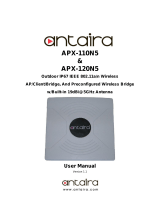
Operating Elements and Connections
N type connector for
2.4/5 GHz antenna
(Radio 1)
N type connector for
2.4/5 GHz antenna
(Radio 0)
N type connector for
2.4/5 GHz antenna
(Radio 1)
N type connector for
2.4/5 GHz antenna
(Radio 0)
Forge posts for
mounting plate
connection
Gore
vent
BLE
antenna
(Internal)
LEDRJ45
connector/
Reset button
Grounding wire
connector
Component Descriptions
Component Description
Status LED Indicates the operational state of your access point such as boot status,
firmware updates and error states. For details, see table “LED Status” below.
Radio LED Indicates the radio mode your access point is currently
operating in. For details, see table “LED Status” below.
Mesh LED Indicates whether the access point has Mesh activated.
RJ45 connector Primary Ethernet port to connect your access point to your network. This port
needs to be connected to a PoE capable source (PoE Injector or PoE switch)
to power your access point. There is no dedicated DC power source available.
Sophos offers suitable PoE injectors for purchase as an optional accessory.
Reset button Allows you to reboot the device and reset its configuration to the
factory default. For details, please see section “Reboot & Reset”
Gore Vent Prevents excessive heat build-up inside the product
while still preventing moisture entry
Grounding Wire
Connector
Used for permanently connecting the APX to earth ground to adequately
ground the chassis and protect the operator from electrical hazards.
N Type connector Used for connecting the standard Omni- or
optional Sector/Directional antennas
Forge posts Used for connecting the mounting bracket.
LEDs
Status
Off Off AP is off or reboot started
Green Solid Normal operation
Flashing AP is booting and connecting to wireless
controller or applying configuration
*
Amber Solid AP has no connection to the wireless controller
Flashing AP is not claimed by wireless controller
Red Solid Error, no wireless controller found. AP will
reboot (if not yet claimed by a controller). Check
network connection if error persists.
If reset button pressed: AP preparing configuration reset
Flashing slowly Configuration reset in progress
*
Flashing fast Firmware update in progress
*
Note: Do not disconnect from power
Radio
Green Solid AP is operating in 2.4 and 5 GHz mode
Amber Solid AP is operating in dual 5 GHz mode
Red Solid AP is operating 1 Radio mode 2.4 OR 5 GHz
Mesh
Off Off No Mesh activated
Green Solid Mesh activated
* Your AP should recover from this state after a maximum of 5 minutes.
3APX 320X
Operating Instructions
Connection and Configuration
Your access point can be managed by a wireless controller located in Sophos
Central. The initial connection of your access point to your network and the
wireless controller is described in the APX Quick Start Guide which was shipped
with your device or is available under www.sophos.com/get-started-ap.
For the access point to communicate with Sophos Central servers the following
ports will need to be open on your firewall:
Ì 443 (HTTPS)
Ì 80 (HTTP)
Ì 123 (NTP)
After successful connection you can start your initial configuration.
Setting up your access point in Sophos Central
You will need a Sophos Central account to manage your access points from
Sophos Central. Please go to https://central.sophos.com to sign in under your
account or create a new account.
After signing in select Wireless from the popup screen or click on Wireless in the
left navigation to get started.
Follow the Onboarding Wizard to register your access point.
For more information, please see the Sophos Central Admin Help.
Setting up your access point in XG Firewall
Please note: Support for the APX 320X will be added in maintenance releases for
SFOS v18.x and UTM 9.x at a later date. Please check https://community.sophos.
com/kb/en-us/124444 for the most current information.
4APX 320X
Operating Instructions
Reboot & Reset
Your access point can be rebooted with the installed configuration or reset to the
factory default configuration depending on how long you press and hold the reset
button.
Reboot with current image and configuration
1. Press reset button
2. Release reset button
3. AP reboots (LED will go off, then will turn to solid green)
Reboot with current image and clear configuration
1. Press and hold reset button
2. AP reboots (LED will go off and then switch to green briefly)
3. LED will turn solid red for 5 sec. You can still cancel
the configuration clearance process by releasing the
reset button before the LED starts blinking
4. LED will blink red (configuration will be cleared)
5. Release reset button
6. AP reboots with factory default settings
Reset
Button
Status LED
Released
Pressed
Solid Solid Blinking
Reboot Reboot clear config
5 Sec
Off
5APX 320X
Operating Instructions
Technical specifications
APX 320X
Environment
Power consumption 18.9 W (max.)
Power over Ethernet
(PoE) requirements
802.3at
Operating temperature -40° to 55° C
Storage temperature -40° to 80° C
Humidity 10-95% non-condensing
Hazardous substances RoHS-2 and REACH compliant
Physical specification
I/O ports 1x RJ45 10/100/1000 Ethernet w/PoE (802.3at)
1x Reset button
Memory 512 MByte DDR3L
512 Mbyte NAND Flash
16 Mbyte SPI NOR Flash
Mounting Wall-mount hang
Pole mount
Dimensions
(Width x Depth x Height)
260.5 x 180 x 87 mm (10.26 x 7.09 x 3.43 inches)
Weight 1.42 kg (3.13 lbs)
Wireless specification
Radios 1x 2.4 GHz/5 GHz dual-band
1x 5 GHz single band
1x Bluetooth low energy (BLE for future use)
Antennas 4x omni-directional external dual-band
antennas for Radio-0 and Radio-1
1x internal 2.4 GHz antenna for BLE
Antenna Peak Gain 3.2 dBi at 2.4 GHz, 6.0 dBi at 5 GHz
MIMO capabilities 2x2:2
Supported WLAN standards IEEE 802.11 a/b/g/n/ac Wave 2 (Wi-Fi 5)
SSIDs 8 per radio, 16 in total (with dual radios active)
Max. Throughput Dual 5 GHz Mode
*
: up to 867 Mbps (5 GHz) + 867 Mbps (5 GHz)
Dual-band Mode
*
: up to 300 Mbps (2.4 GHz) + 867 Mbps (5 GHz)
Single 5 GHz Mode
**
: up to 867 Mbps
* Not available in the countries listed here: https://support.sophos.com/support/s/article/KB-000039850
** For the countries listed here: https://support.sophos.com/support/s/article/KB-000039850
Performance
Band/Mode Data Rate TX Power
Maximum
EIRP (dBm)
RX Sensitivity
(dBm)
2.412-2.472 GHz
(11b)
1 Mbps 24 -93
2 Mbps 24 -90
5.5 Mbps 24 -86
11 Mbps 24 -82
2.412-2.472 GHz
(11g)
6 Mbps 24 -89
9 Mbps 24 -88
12 Mbps 23 -86
18 Mbps 23 -84
24 Mbps 22 -81
36 Mbps 22 -77
48 Mbps 21 -73
54 Mbps 21 -72
6APX 320X
Operating Instructions
Performance
2.412-2.472 GHz
(11n HT20)
MCS 0 24 -88
MCS 1 24 -85
MCS 2 23 -83
MCS 3 23 -80
MCS 4 22 -76
MCS 5 22 -72
MCS 6 21 -71
MCS 7 21 -70
MCS 8 20 -69
5.180-5.825 GHz
(11a)
6 Mbps 26 -83
9 Mbps 26 -82
12 Mbps 25 -81
18 Mbps 25 -77
24 Mbps 24 -73
36 Mbps 24 -69
48 Mbps 23 -68
54 Mbps 23 -66
5.180-5.825 GHz
(11ac VHT20)
MCS0 26 -82
MCS1 26 -78
MCS2 25 -75
MCS3 25 -74
MCS4 24 -71
MCS5 24 -67
MCS6 23 -66
MCS7 23 -65
MCS8 17 -62
5.180-5.825 GHz
(11ac VHT40)
MCS0 26 -80
MCS1 26 -76
MCS2 25 -73
MCS3 25 -72
MCS4 24 -69
MCS5 24 -65
MCS6 23 -64
MCS7 23 -63
MCS8 22 -59
MCS9 22 -57
5.180-5.825 GHz
(11ac VHT80)
MCS0 26 -76
MCS1 26 -74
MCS2 25 -71
MCS3 25 -70
MCS4 24 -67
MCS5 24 -63
MCS6 23 -62
MCS7 23 -61
MCS8 22 -56
MCS9 22 -54
7APX 320X
Operating Instructions
Radiation patterns
2.4 GHz Band
H-plane V-plane
—2400 (MHz) —2450 (MHz) 2500 (MHz)
5 GHz Band
H-plane V-plane
—4900 (MHz) —5150 (MHz) —5350 (MHz) —5475 (MHz) —5725 (MHz) —5875 (MHz)
8APX 320X
Operating Instructions
Optional Sector / Directional Antennas
Technical specifications
Optional Sector / Directional Antennas
120° Sector Antenna
Frequency range 2400~2500 MHz 5150~5850 MHz
Port V-pol. / H-pol. V-pol. / H-pol.
Antenna Gain 10.6~10.8 dBi) / 10.0~11.4 dBi 12.5~13.1 dBi / 11.6~12.9 dBi
HPBW / Horizontal 76~77 deg / 63~66 deg 40~61 deg / 52~76 deg
HPBW / Vertical 24~25 deg / 26~28 deg 11~13 deg / 11~13 deg
Isolation 20 dB
Impedance 50 Ohms
Connector N Jack
Dimensions
(Height x Width x Depth)
320 x 200 x 20.5 mm (12.6 x 7.87 x 0.81 inches)
30° Directional Antenna
Frequency range 2400~2500 MHz 5150~5850 MHz
Port V-pol. / H-pol. V-pol. / H-pol.
Antenna Gain 11.6~11.8 dBi) / 11.6~12.0 dBi 10.6~11.0 dBi / 10.4~11.5 dBi
HPBW / Horizontal 36~37 deg / 35~36 deg 33~35 deg / 26~36 deg
HPBW / Vertical 34~35 deg / 36~38 deg 32~39 deg / 30~41 deg
Isolation 20 dB
Impedance 50 Ohms
Connector N Jack
Dimensions
(Height x Width x Depth)
320 x 200 x 20.5 mm (12.6 x 7.87 x 0.81 inches)
9APX 320X
Operating Instructions
Radiation patterns Sector Antenna – Horizontal Polarization
2.4 GHz Band
H-plane V-plane
—2400 (MHz) —2450 (MHz) 2500 (MHz)
5 GHz Band
H-plane V-plane
—4900 (MHz) —5150 (MHz) —5350 (MHz) —5475 (MHz) —5725 (MHz) —5875 (MHz)
10APX 320X
Operating Instructions
Radiation patterns Sector Antenna – Vertical Polarization
2.4 GHz Band
H-plane V-plane
—2400 (MHz) —2450 (MHz) 2500 (MHz)
5 GHz Band
H-plane V-plane
—4900 (MHz) —5150 (MHz) —5350 (MHz) —5475 (MHz) —5725 (MHz) —5875 (MHz)
11APX 320X
Operating Instructions
Radiation patterns Directional Antenna – Horizontal Polarization
2.4 GHz Band
H-plane V-plane
—2400 (MHz) —2450 (MHz) 2500 (MHz)
5 GHz Band
H-plane V-plane
—4900 (MHz) —5150 (MHz) —5350 (MHz) —5475 (MHz) —5725 (MHz) —5875 (MHz)
12APX 320X
Operating Instructions
Radiation patterns Directional Antenna – Vertical Polarization
2.4 GHz Band
H-plane V-plane
—2400 (MHz) —2450 (MHz) 2500 (MHz)
5 GHz Band
H-plane V-plane
—4900 (MHz) —5150 (MHz) —5350 (MHz) —5475 (MHz) —5725 (MHz) —5875 (MHz)
13APX 320X
Operating Instructions
Mounting instructions
There are various mounting options available allowing you to hang your access
point on the wall or mount it on a pole. Both options require the use of the
mounting bracket which is shipped with your access point. The following
sections provide detailed instructions on each of these options.
Mounting bracket
Mounting holes
Vertical orientation
mounting clamp slots
Horizontal orientation
mounting clamp slots
Mounting
attachment slots
Mount plate
attachment screw
Wall mount
1. Use the mounting bracket to mark the screw mounting positions on the wall
2. Attach the access point to the bracket by hanging the 4 forge posts
into the attachment slots of the bracket and pressing it down.
3. Tighten the attachment screw to fix the access point to the bracket.
1.
2. 3.
Tighten the
attachment
screw
14APX 320X
Operating Instructions
Pole mount
1. Attach the two metal clamps to the back of the mounting bracket using the
vertical or horizontal mounting slots (according to the desired orientation).
2. Hold the bracket against the pole and tighten the metal clamps.
3. Attach the access point to the bracket by hanging the 4 forge posts
into the attachment slots of the bracket and pressing it down.
4. Tighten the attachment screw to fix the access point to the bracket
1. 2.
3.
Tighten the
attachment
screw
4.
15APX 320X
Operating Instructions
Sector / Directional Antenna Mounting Instructions
1. Attach the articulating mount to the back of the Sector /
Directional antenna using four of the supplied M6 nuts.
2. Fix the T-form bracket to the pole by using the two supplied stainless steel
hose clamps.
Please note: The clamps can be used for poles
of 35-80 mm (1.5-3 inches) diameter
3. Fix the articulating mount to the T-form bracket by using the
supplied M8x40 bolts, nut, spring washer and washer.
4. Direct the antenna upward or downward (max.
angle is 27°) and fix it into place.
1.
27
0
27
0
Use a No. 12
hexagonal
wrench to lock
the M8 nut.
4.
M8x40
Screw Bolts
T-form
Bracket
Washer
Spring Washer
M8 Nut
3.
2.
16APX 320X
Operating Instructions
Connect the Sector / Directional Antenna to the Access Point
Connect the antenna to your APX 320X access point by using the supplied
cables. You can use your sector/directional antenna either in combination with
the standard omni-directional antennas or with another sector/ directional
antenna.
Choose the appropriate connection for the scenario which best fits your use case
- as shown in the table below.
Scenario Radio 0 (2.4/5 GHz High Band) Radio 1 (5 GHz Low Band)
a Sector/Directional (Top/Bottom) Sector/Directional (Top/Bottom)
b Sector/Directional (Top/Bottom) Omni (Top/Bottom)
c Omni (Top/Bottom) Sector/Directional (Top/Bottom)
NOTE: If you use the sector/directional antenna with the APX 320X in some
countries, the use of Radio-1 may not be possible. Regulatory restrictions in
some countries prohibit the use of low band 5 GHz channels which do not
support DFS in outdoor environments. Therefore, Radio-1 cannot be configured
when used in the countries listed here: https://support.sophos.com/support/s/
article/KB-000039850. In those countries, this model will function as a single
radio device (2.4 OR 5 GHz), your antennas should be connected to Radio-0 only,
and concurrent use of the sector/directional and omni-directional antennas is
not possible.
a. b. c.
Configure Sector / Directional Antenna Software Settings
Once the external antenna is connected, please select the corresponding
antenna settings in your Sophos Central Wireless admin account. Once selected
and the configuration synched, the AP reboots and the correct power values will
be set.
WARNING: Failure to configure the correct antenna settings may place the AP
outside of regulatory limits. The administrator is responsible for ensuring this
configuration is correct.
Operating Instructions
United Kingdom and Worldwide Sales
Tel: +44 (0)8447 671131
North American Sales
Toll Free: 1-866-866-2802
Australia and New Zealand Sales
Tel: +61 2 9409 9100
Asia Sales
Tel: +65 62244168
© Copyright 2020. Sophos Ltd. All rights reserved.
Registered in England and Wales No. 2096520, The Pentagon, Abingdon Science Park, Abingdon, OX14 3YP, UK
Sophos is the registered trademark of Sophos Ltd. All other product and company names mentioned are
trademarks or registered trademarks of their respective owners.
2020-09-07 OINA (PC)
  • Page 1 1
  • Page 2 2
  • Page 3 3
  • Page 4 4
  • Page 5 5
  • Page 6 6
  • Page 7 7
  • Page 8 8
  • Page 9 9
  • Page 10 10
  • Page 11 11
  • Page 12 12
  • Page 13 13
  • Page 14 14
  • Page 15 15
  • Page 16 16
  • Page 17 17
  • Page 18 18

Sophos APX 320X Operating Instructions Manual

Category
WLAN access points
Type
Operating Instructions Manual
This manual is also suitable for

Sophos APX 320X is a high-performance wireless access point featuring the latest 802.11ac Wave 2 technology for an exceptional user experience. Easily managed via Sophos Central, it offers seamless integration, allowing you to set up and manage your network from anywhere. With its dual-radio design, the APX 320X delivers up to 1.734 Gbps throughput, ensuring reliable and blazing-fast connectivity for your devices.

Ask a question and I''ll find the answer in the document

Finding information in a document is now easier with AI