Sophos AP6840 User guide

Type
User guide

Sophos AP6840 is a high-performance 802.11ax access point designed to deliver fast and reliable wireless connectivity for businesses of all sizes. With its advanced features like OFDMA, MU-MIMO, and beamforming, the AP6840 can handle even the most demanding traffic loads, ensuring a seamless wireless experience for users. It also comes equipped with Sophos Central management, making it easy to set up, configure, and manage your wireless network from a single pane of glass.

Sophos AP6840 is a high-performance 802.11ax access point designed to deliver fast and reliable wireless connectivity for businesses of all sizes. With its advanced features like OFDMA, MU-MIMO, and beamforming, the AP6840 can handle even the most demanding traffic loads, ensuring a seamless wireless experience for users. It also comes equipped with Sophos Central management, making it easy to set up, configure, and manage your wireless network from a single pane of glass.

Quick Start Guide
Sophos AP6 Series
For more information about your appliance, scan the QR code or visit
www.sophos.com/get-started-firewall
United Kingdom Sales
Tel.: +44 (0)8447 671131
North American Sales
Toll Free: 1-866-866-2802
Australia and New Zealand Sales
Tel.: +61 2 9409 9100
Sales DACH
(Deutschland, Österreich, Schweiz)
Tel.: +49 (0) 611 585 8-0
Tel.: +49 (0) 721 255 16-0
Japan Sales
Tel.: +81 3 3568 7550
China Sales
Tel.: +86-10-6567 5820
Shanghai Sales
Tel.: +86-21-32517160
2022-11-17 QSG-EN (DD)
© Copyright 2022. Sophos Ltd. All rights reserved.
Registered in England and Wales No. 2096520, The Pentagon, Abingdon Science Park,
Abingdon, OX14 3YP, UK. Sophos is the registered trademark of Sophos Ltd.
All other product and company names mentioned are trademarks or registered
trademarks of their respective owners.
LEDs
AP6 420(E)/840(E)
Off Off AP is off or reboot started
Green Solid Normal Operation
Flashing AP is booting and connecting to wireless controller
Amber Solid AP has no connection to the wireless controller
Flashing AP is not claimed by wireless controller
Red Solid Error, no wireless controller found. AP will reboot (if not yet claimed
by a controller). Check network connection if error persists
If reset button pressed: AP preparing configuration reset
Flashing Slowly Configuration reset in progress*
Flashing Fast Firmware update in progress**
AP6 420X
Status Radio Mesh
Off Off Off AP is off or reboot started
Flashing Green Off Off AP is booting and connecting to wireless
controller or applying configuration*
Flashing Green Flashing Green Off Configuration reset in progress*
Flashing Green Flashing Green Flashing Green Error, no wireless controller found.
AP will reboot (if not yet claimed by a
controller). Check network connection
if error persists. If reset button pressed:
AP preparing configuration reset
Flashing Fast Green Off Off Firmware update in progress**
Solid Green Flashing Green Flashing Green AP has no connection to the wireless controller
Solid Green Flashing Green Flashing Fast Green AP is not claimed by wireless controller
Solid Green Off Off or Solid Green AP is operation in Single-Band
Solid Green Green Off or Solid Green AP is operation in Dual-Band
* Your AP should recover from this state after a maximum of 5 minutes.
** Note: Do not disconnect from power, nor reboot or reset the device. When the device connects to Sophos Central or
Sophos Firewall for the first time, it might take up to 15 minutes to update firmware
Box contents
Indoor Access point
Outdoor Access point
4 screws
M6*1.0P*25mm
4 wall anchors
5/16*1-1/4" for
wall-mount
1 M25 cable gland
2 adjustable
metal clamps
Grounding wire with
washer and screw
4 x omni-directional
2.4/5 GHz antenna
Outdoor Access Point Grounding
WARNING: Model AP6 420X has a separate protective earthing terminal on the chassis
which must be permanently connected to earth ground to adequately ground the chassis
and protect the operator from electrical hazards. The installation of the earth grounding
must be done by a skilled service personnel.
CAUTION: Before you begin the installation, ensure that service personnel has attached an appropriate
grounding lug to the grounding cable that you supply.
Power installation must be performed by a qualified electrician in accordance with National Electrical
Code, ANSI/NFPA 70 and Canadian Electrical Code, Part I, CSA C22.1.
To connect earth ground to unit:
ÌConnect one end of the grounding cable to a proper earth ground.
ÌPlace the grounding lug attached to the grounding wire over the protective earthing terminal.
ÌSecure the grounding lug to the protective earthing terminal with the supplied washers and screws.
ÌDress the grounding cable and ensure that it does not touch or block access to other components.
Protective Earthing Terminal
WARNING: Prior to powering on the unit, connect the frame of the unit to earth. For the
earthing wire, green and yellow insulation is required, and the cross-sectional area of the
conductor must be more than 0.75mm2 or 18 AWG.
Mounting bracket for
wall and pole mount
AP6 420(E)/840(E)
AP6 420X
2 screws
2 wall anchors for
wall-mount
4 screws to attach
bracket to back of AP
AP6 840/840E AP6 420/420E
AP6 420X
Console port
Power connector
(AP6 420 only) LAN port (PoE)
Reset button
Console port LAN port (PoE)
Reset button LAN 2 port (AP 840E only)
N type connector
for 2.4GHz antenna
N type connector
for 2.4GHz antenna
N type connector
for 5GHz antenna
N type connector
for 5GHz antenna
Gore vent
LEDs
RJ45
connector/
Reset button
Forge posts for
mounting plate
connection
Mounting bracket for wall
and ceiling (T-bar)
Quick Start Guide and
Safety Instructions
Quick Start Guide and
Safety Instructions
Reboot with current image and clear configuration (Outdoor Access Points)
1. Press and hold reset button for 5 sec.
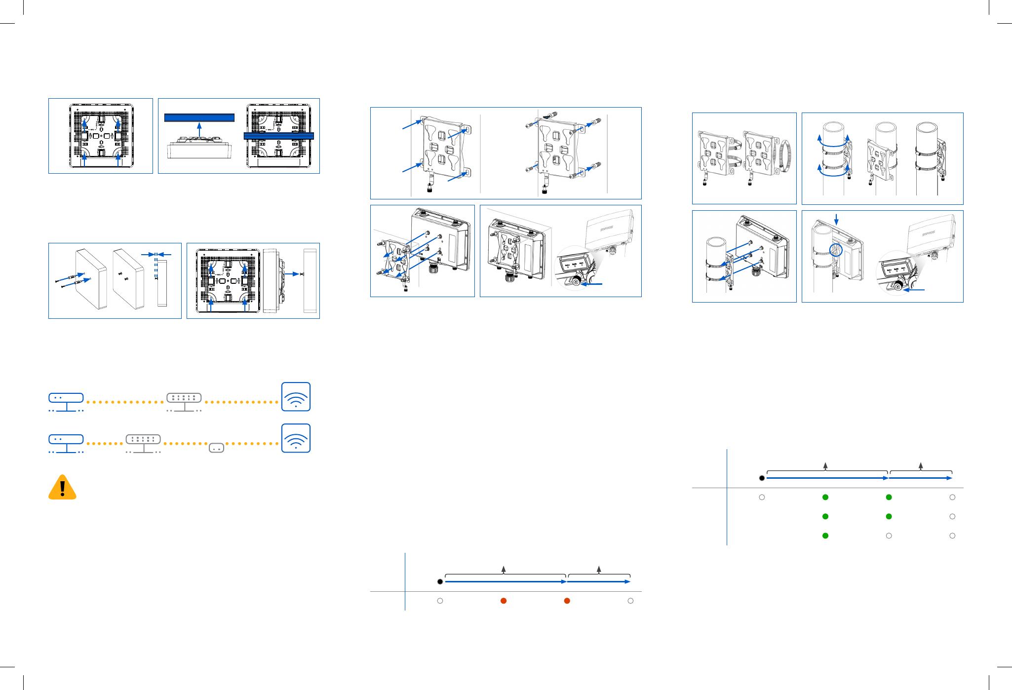
2. Status, Radio, and Mesh LEDs will start flashing for 5 sec. You can still cancel the configuration
clearance process by releasing the reset button before the Mesh LED turns Off. In that case the AP
will reboot as described above.
3. After 5 sec. Mesh LED turns off. Status and Radio LEDs continue flashing.
4. Release reset button (configuration will be cleared).
5. AP reboots with factory default settings.
Radio LED
Mesh LED
Reset Button
Status LED
If button released
AP will reboot
Pressed
Flashing Flashing
5 Sec
If button released AP will reboot
and config will be cleared
Off Off
5 Sec
Flashing Flashing Off
Flashing Off Off
Connecting the Access Point
Sophos Firewall
or Router
Switch Access PointPoE Injector
Sophos Firewall
or Router
PoE Switch Access Point
WARNING: To ensure safe operation, model AP6 420X is intended to be used only with
Listed, IEEE 802.3at-compliant, Power over Ethernet Power Sourcing Equipment that is
designed for connection to outdoor devices. The power supply cord(s) of the PoE injector
or PoE Switch must be plugged into socket-outlet(s) with earthing connection. If you
need assistance with selecting or purchasing an appropriate power source, please contact your local
Sophos sales representative.
Connect the LAN (PoE) port of the access point to a PoE+ switch or PoE+ injector using an RJ45
Ethernet cable.
Note: Model AP6 840E requires a PoE++ (802.3bt) switch/injector
Model AP6 420 can also be connected to an Ethernet switch and powered by a separate Power Supply
(available as an accessory from your Sophos partner). The access point will now boot and try to receive
an IP address via DHCP (either from the Sophos firewall or another DHCP server in your network).
After successfully receiving an IP address, the access point attempts to communicate with Sophos
Central. In order to do so, the firewall needs to either be the default gateway of the access point or be
on the default route (most likely your route to the internet).
Whilst waiting for DHCP and searching for the wireless controller, the access point status LED will
show its current state (please see LED table).
Configuration
After successful connection to the wireless controller the status LED turns to solid green. The access
point is now ready to be managed.
Please refer to the Sophos Central online help to start the configuration of your access point.
Reboot & Reset
Reboot with current image and configuration
1. Press reset button.
2. Release reset button.
3. AP reboots (Status LED will go off, then will start blinking after some seconds and turn to solid green
after reboot is complete).
Reboot with current image and clear configuration (Indoor Access Points)
1. Press and hold reset button for 5 sec.
2. Status LED will turn solid red for 5 sec. You can still cancel the configuration clearance process by
releasing the reset button before the Status LED starts flashing. In that case the AP will reboot as
described above.
3. After 5 sec. Status LED will start flashing red.
4. Release reset button (configuration will be cleared).
5. AP reboots with factory default settings.
Reset Button
Status LED
If button released
AP will reboot
Pressed
Solid Flashing
5 Sec
If button released AP will reboot
and config will be cleared
Off Off
5 Sec
Mounting (Outdoor Access Points)
Wall mount
1. Use the mounting bracket to mark the screw mounting positions on the wall.
2. Attach the access point to the bracket by hanging the 4 forge posts into the attachment slots of the
bracket and pressing it down.
3. Tighten the attachment screw to fix the access point to the bracket.
1.
2. 3.
Tighten the
attachment
screw
Pole Mount
1. Attach the two metal clamps to the back of the mounting bracket using the vertical or horizontal
mounting slots (according to the desired orientation).
2. Hold the bracket against the pole and tighten the metal clamps.
3. Attach the access point to the bracket by hanging the 4 forge posts into the attachment slots of the
bracket and pressing it down.
4. Tighten the attachment screw to fix the access point to the bracket.
1.
3.
2.
4.
Tighten the
attachment
screw
Mounting (Indoor Access Points)
Ceiling Mount
1. Fix the bracket to the rear of the Access Point by using 4 of the supplied screws.
2. To install, put the access point underneath the ceiling rail (t-bar) and push it into place. To dismount,
push the spring locks to the side and pull the access down.
1. 2.
Wall Mount
1. Mark the wall where you want to insert the provided anchors which must be 6.2cm (2.44 in.) apart
2. Drill the 2 supplied wall anchors into the wall at the marked positions and screw 2 supplied screws
into them. Make sure they stand out ~6.7mm
3. Fix the bracket to the rear of the Access Point by using 4 of the supplied screws.
4. Hang the access point (with the mounted bracket) on the wall by aligning the key holes with the
mounted screws
1. Wall
6.7mm ±2.0
2.
  • Page 1 1
  • Page 2 2

Sophos AP6840 User guide

Type
User guide

Sophos AP6840 is a high-performance 802.11ax access point designed to deliver fast and reliable wireless connectivity for businesses of all sizes. With its advanced features like OFDMA, MU-MIMO, and beamforming, the AP6840 can handle even the most demanding traffic loads, ensuring a seamless wireless experience for users. It also comes equipped with Sophos Central management, making it easy to set up, configure, and manage your wireless network from a single pane of glass.

Ask a question and I''ll find the answer in the document

Finding information in a document is now easier with AI