Page is loading ...

____________________________________________________________________________________________________
5800 W. Donges Bay Road. Mequon WI, 53092 Phone: (888) 686-3472 Fax: (262) 512-4219
www.hayesdiscbrake.com
hayestech@hayesbicycle.com
A. Pad Replacement - Full Hydraulic Systems and MX-1 Mechanical
1. Remove the wheel.
Note: It is not necessary to remove the caliper from the frame or fork, but it may make the installation of the new
pads easier if the caliper is removed.
2. Using the tab in the center of the pad backing plate, pull the pad toward the center of the caliper and out. There is a
spring that holds them in place. That spring snaps on to the post at the center of the piston.
3. Repeat the steps for the other side pad.
To replace the pads...
Note: For the MX-1 Mechanical brake, skip to step #5
4. Using the boxed end of a 10mm wrench, push the caliper pistons back until they bottom. This will give you more
room to fit in the new pads. Take care not to push on the aluminum post in the center of the piston.
Caution: Don’t push on the post in the center of the piston because that will bend the post. Walk the piston back and
forth until the piston is all the way back in the bore. Do the same thing on the other side.
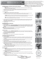
Note: There are two different brake pads, an inner and outer (or a right and a left). On the outer pad the tab is offset.
On the inner pad the tab is in the center. See Photo
5. Put the outer pad in first. Use the tab in the center of the pad backing plate to push the new pads into place. Angle
the pad slightly so the post is towards the center of the caliper and push the pad until it snaps into place. Check that
the pad is locked into position.
6. Now repeat the procedure for the outer pad.
7. Install the wheel.
C. Mounting the Caliper to the Frame or Fork
Warning: When following any of the procedures below, be sure to keep your hands and fingers from getting
caught in the disc. Failure to do so could result in injury.
1. Remove the wheel(s).
2. For some installations it will be necessary to mount a mount bracket to accept the Hayes Disc Brake caliper.
Mount the mount bracket to the frame or fork using (2) M6 x 1.0 18.4mm long mount bolts. Torque the bolts to
110 in-lbs (12.43 Nm).
3. Mount the caliper to the frame or mount bracket using (2) M6 x 1.0 18.4mm long mount bolts and (2) mount
washers. Snug the bolts, but leave them loose enough so that caliper will move on its slots.
Caution: For post mount forks you will need to use (2) M6 x 1.0 22mm long mount bolts. These bolts are supplied
in your aftermarket kit or supplied from the bike manufacturer. Failure to use the longer bolt may result in fork
damage that will not allow you to tighten down your caliper properly.
4. Re-install the wheel(s).
5. Squeeze and hold the brake lever. While holding the brake lever, shake the caliper to position it in its natural
centered position over the disc. While squeezing the lever, tighten the mounting bolts.
Warning: Do not adjust the caliper while the caliper is hot.
Warning: Do not adjust the caliper while the wheel is spinning.
6. Release the lever, spin the wheel. Check that it spins freely and that the gaps, between the pad and the disc, are
equal. If the gaps are unequal, or if there is drag, readjust the caliper position by loosening the mounting bolts
and adjusting the caliper as needed. Hint: A white piece of paper can be used as a background to help sight
down the disc looking for equal clearance between the pads and disc.
7. When the gaps are equal and the wheel spins freely (without drag), torque the mounting bolts to 110 in-lbs
(12.43 Nm).
Caution: For post mount forks, torque the mounting bolts to 80 in-lbs.
8. Repeat above procedure for other wheel.
D. Mounting the Disc to the Hub
Note: Mounting the brake disc to the wheel is a simple matter, but one that requires care. If the wheel has to be
rebuilt, have it done by a qualified technician using a 3 cross spoke pattern. We recommend the use of steel,
quick release skewers only.
1. Clean the disc and the hub mounting surface with isopropyl alcohol.
Warning: Do NOT use automotive disc brake cleaners.
2. Place the disc on the hub mounting surface. Be sure that the arrow on the disc is pointing in the same direction
of the forward wheel rotation.
3. Using a Torx T25 driver, install, tighten, and torque the disc screws to 50in-lbs (5.65Nm), in a star pattern
sequence. See Diagram
4. Check and retorque the disc screws after 12 hours.
Warning: The disc should be periodically inspected for wear and damage.
The minimum disc thickness is 1.52mm
Step C3
Step A2
Step A4
Full Hydraulic and
MX-1 Brake Pads
MX-2 Brake Pads
Step B3
Torqueing Sequence
Step C6
45-14575E
Service Kit Instructions
Pad Replacement, Mount Brackets, Disc Installation
B. Pad Replacement - MX-2, MX-3 MX-4, MX-5, CX-5 Mechanical
1. Remove the wheel.
2. Using a 2mm Allen wrench, loosen the grub screw on top of the caliper. It is located above the inner pad adjuster.
3. Using a needle nose pliers, remove the outer pad first. Note: The outer pad is away from the wheel. To do this,
Note: If you do not remove the outer pad first, you will not be able to remove the pads.
4. Repeat the above steps for the inner pad.
Note: The inner and outer brake pads are identical. See Photo
To replace the pad.
5. Using a needle nose pliers, install the inner pad in first. Note: The inner pad is the pad closest to the wheel.
Use the tab in the center of the pad backing plate to push the new pads into place. Angle the pad slightly until
the force of the magnet pulls the pad into place.
6. Now repeat the procedure for the outer pad.
7. Install the wheel.
8. Using a 5mm Allen wrench, adjust the inner pad adjuster to the proper pad gap. Once set to proper gap use the 2mm Allen
to tighten grub screw down onto pad adjuster.
Then using a 5mm Allen wrench, turn the inner pad adjuster counter-clockwise until one engagement thread is
showing.
pull the tab in the center of the pad backing plate toward the center of the caliper and out. The pad is held in with a
magnet.
Note: MX-5 brake pads come out of the top of the caliper. All others come out of the bottom of the caliper.
The following procedures cover the installation of Hayes items purchased as an aftermarket item. A qualified technician with
the proper tools should install the brake components. Improper installation could cause severe or fatal injuries.
Warning: When following any of the procedures below, be sure to keep your hands and fingers from getting caught in the disc.
Warning: With use, disc brake components may become very hot. Allow components to cool before servicing your bike.
/