Page is loading ...

HYDRAULIC DISC BRAKE
INSTALLATION, SERVICE,
MAINTENANCE MANUAL
45-21883Web
Congratulations. You have purchased a Hayes Disc Brake system. This
Manual is intended to provide the information necessary for normal
maintenance and service of the Hayes Disc Brake system. Although the
steps and procedures are relatively
simple, they should not be attempted
until you are thoroughly familiar with the entire set of procedures. Images
have been provided to help you in the steps and procedures.
Warning: As a serious rider you are well aware of the need to practice safety
in all aspects of the sport. This includes service and maintenance practices
as well as riding practices. Before each ride, always check your brakes for
proper function and the brake pads for wear. When you ride, always wear a
helmet.
Warning: When you need to install any of the disc brake components, that
installation work should be done by a qualified technician with the proper
tools. Improper installation could cause severe or fatal injuries.
Warning: This brake has been designed for use on a single person mountain
bike. The use on any other vehicle or device will void the warranty and can
cause serious injury.
Warning: With use, disc brake components may become very hot. Always
allow components to cool before attempting to service your bike.
Warning: When following any of the procedures below, be sure to keep your
hands and fingers from getting caught in the disc. Failure to do so could
result in injury.
Warning: For riders using the brakes in downhill conditions, it is
recommended that you use the 8" disc version of the Hayes Brake. Not all
frames and forks will accept and 8" disc. Please check with your frame or
fork manufacturer or
www.hayesdiscbrake.com for 8" disc compatibility.
Consistently using the 6" disc in downhill conditions may cause the brake
fluid to boil.
Warning: If your bike is involved in a fall or crash it is recommended you
check your brakes before riding to ensure they are functioning properly. The
following checks should be performed: Check that all components are
securely mounted to the handlebar, frame, fork, or wheel; check for proper
pad installation and retention; check that the brake builds and holds pressure;
check hose and fittings for kinks or leaks; check master cylinder body and
caliper for damage. Always have a qualified bike mechanic check your brakes
if you suspect damage.
CAUTIONS, WARNINGS, NOTES, ETC
Within this manual are specifically labeled comments intended to bring special attention to a general procedure or detailed step. Be aware of, and understand, the
meaning of these labels.
Warning: Means that there is the possibility of personal injury to you or to others.
Caution: Means that there is the possibility of damaging the brake or the bike.
Note: Provides general information.
Hint: Provides information that can help you properly complete a specific procedure.
STARTING OUT
Personal Preference and Adjustment
In most cases, the disc brake system has been pre-assembled for your bike. However there are a couple of adjustments that you can make to match your particular
physical characteristics or personal preferences.
Positioning the Master Cylinder and Lever
1. Loosen, but do not remove, the handle bar clamp.
2. Then, position the Master Cylinder and Lever on the handlebar in your desired position.
3. Torque the handlebar clamp screw to 30 in-lbs (3.37Nm)
Caution: Tighten the handlebar clamp screws so there is an equal gap at between
the master cylinder and clamp at both clamp screws.
Lever Reach Adjustment
Stroker Ryde :
Adjust the brake lever reach by using a 2.5mm Allen wrench and turning the push rod that goes through the lever adjuster bushing. Do not attempt to force the
adjustment screw beyond its limits.
Stroker Trail/Carbon and Gram :
Adjust the brake lever reach by turning the reach adjustment knob. Turning the knob counter clockwise will adjust the lever closer to the handle bar. Turning the knob
clockwise will adjust the lever farther from the handle bar. Do not attempt to force the adjustment screw beyond its limits.
Caliper Hose Routing ( For Stroker Trail/Carbon and Gram Only )
The banjo on the caliper can be rotated to accommodate your frame or fork. Loosen the banjo bolt 1/4 turn and rotate the banjo to the desired location. (Note:
loosening the banjo more than 1/4 turn may introduce air in the system). Tighten the banjo to 60 in-lb (6.78 Nm).
Recommended Fluids and Lubricants
Use only DOT 3 or DOT 4 brake fluid. Do not use any petroleum-based lubricants, as this will cause the rubber parts to swell. HB Performance Systems recommends the
use of DOT 3 or DOT 4 brake fluid. Clean the disc and pads only with isopropyl alcohol.
Burnish
Disc brakes require a special burnish period to achieve maximum braking power.
This burnish period last for about 30-40 stops. During this period some noise may occur.
SAFETY INFO
45-21883Web page 1
TM
TM

INSTALLATION
If you have purchased a bike new – with Hayes disc brakes already installed, you will not immediately be required to follow all of the following procedures.
A. Tools Required
Torx T25 driver Open-end wrenches: 6mm, 8mm, 10mm
Torque Wrench Allen Drivers: 2.5mm, 4mm, 5mm
B. Mounting the Disc to the Hub
Note: Mounting the brake disc to the wheel is a simple matter, but one that requires care. If the wheel has to be rebuilt, have it done by a qualified technician using a 3
cross spoke pattern. We recommend the use of a steel, quick release skewers only.
1. Clean the disc and hub mounting surface with isopropyl alcohol (not disc brake cleaners).
2. Place the disc on the hub mounting surface. Be sure that the arrow on the disc is pointing in the same direction of the forward wheel rotation.
3. Using a Torx T25 driver, install, tighten, and torque the disc screws to 50 in-lb (5.65Nm), in a star pattern sequence.
Warning: The disc should be periodically inspected for wear and damage. The minimum disc thickness is 1.52mm
C. Mounting the Caliper to the Frame or Fork
Warning: When following any of the procedures below, be sure to keep your hands and fingers from getting caught in the disc. Failure to do so could result in injury.
1. Remove the wheel(s).
2. For some installations it will be necessary to mount a mount bracket to accept the HB Disc Brake caliper. Mount the mount bracket to the frame or fork using
(2) M6 x 1.0 18.4mm long mount bolts. Torque the bolts to 110 in-lbs (12.43 Nm).
3. Mount the caliper to the frame or mount bracket using (2) M6 x 1.0 18.4mm long mount bolts and (2) mount washers. Snug the bolts, but leave them loose enough so
that caliper will move on its slots.
Caution: For post mount forks you will need to use (2) M6 x 1.0 22mm long mount bolts. These bolts are supplied in your aftermarket kit or supplied from the bike
manufacture. Failure to use the longer bolt may result in fork damage that will not allow you to tighten down your caliper properly.
4. Re-install the wheel(s).
5. Squeeze and hold the brake lever. While holding the brake lever, shake the caliper to position it in its natural centered position over the disc. While squeezing the l
ever, tighten the mounting bolts.
Warning: Do not adjust the caliper while the caliper is hot.
Warning: Do not adjust the caliper while the wheel is spinning.
6. Release the lever, spin the wheel. Check that it spins freely and that the gaps, between the pad and the disc, are equal. If the gaps are unequal, or if there is drag,
readjustthe caliper position by loosening the mounting bolts and adjusting the caliper as needed. Hint: A white piece of paper can be used as a background to help
sight down the disc looking for equal clearance between the pads and disc.
7. When the gaps are equal and the wheel spins freely (without drag), torque the mounting bolts to 110 in-lbs (12.43 Nm).
Caution: For post mount forks, torque the mounting bolts to 80 in-lbs.
8. Repeat above procedure for other wheel.
D. Mounting the Master Cylinder to the Handle Bar
1. Remove the 4mm clamp screws from the master cylinder handlebar clamp.
2. Place the master cylinder on the handlebar.
3. Place the clamp onto the opposite side of the master cylinder and install the two clap screws. Thread the clamp screws loosely into the master cylinder body.
4. Place the master cylinder in the desired position.
5. Tighten the handlebar clamp screws to 30in-lb(3.37 Nm)
Caution: Tighten the handlebar clamp screws so there is an equal gap at between the master cylinder and clamp at both clamp screws.
SERVICE
A. Hose Removal and Assembly (Figure 5)
The following procedures are to be used when replacing or removing the hose.
• Master Cylinder Hose Removal – For Stroker Ryde/Trail/Carbon and Gram
and
Caliper Hose Removal– For Stroker Ryde
1. To take the hose off of the master cylinder end, slide the nose cone down the hose.
2. Using a 8mm box wrench, remove the hose nut and slide it all the way down the hose.
3. Slide the hose out of the end of the master cylinder/caliper. There will be some residual fluid in the hose and master cylinder / caliper. Be careful to avoid spilling that fluid.
4. A new hose insert/compression bushing combination will be needed each time the hose is re-installed. Remove the old compression bushing and hose insert by cutting the hose
next to the compression bushing. The cut needs to be clean with no frayed ends.
• Master Cylinder Hose Assembly– For Stroker Ryde/Trail/Carbon and Gram
and
Caliper Hose Assembly– For Stroker Ryde
1. Cut the hose to the desired length with good scissors or cable cutters. The cut end must be clean and perpendicular to the hose itself.
NOTE: Do not cut the caliper end of the hose for the Stroker Trail/Carbon and Gram as there is a permanent crimp on the hose.
2. When attaching the hose to the master cylinder, slide the nose cone onto the master cylinder side of the hose.
3. Slide the hose nut over the hose.
4. Push the end of the barbed hose insert/compression bushing combination into the end of the hose. Be sure it is inserted flush with the end of the hose.
Always use a new hose insert/compression bushing combination.
5. Slide the hose into the master cylinder/caliper and install the hose nut. Be sure that the hose is inserted completely into the master cylinder end. Be sure the hose
remains inserted while tightening.
6. Using an 8mm open-end wrench, torque the hose nut to 70 +/- 5 in/lb.
7. Bleed the system
45-21883Web page 2

• Caliper Hose Removal - For Stroker Trail/Carbon and Gram
1. To take the hose off the caliper end, remove the banjo bolt using a 4mm Allen wrench.
2. When removing the banjo assembly completely from the caliper, be sure that
the two banjo o-rings are not lost.
Note: The end of the Stroker Trail/Carbon and Gram caliper hose is a permanent crimp. Therefore the connection cannot be trimmed to size or repaired. Shortening
of the hose must be done at the master cylinder end. If the caliper hose connection is damaged, the hose must be completely replaced with a new hose with a
permanent crimp attached.
••
••
• Caliper Hose Assembly - For Stroker Trail/Carbon and Gram
1. Install the banjo bolt through the banjo. Be sure that there is a banjo o-ring on
each side of the banjo.
2. Position the angle of the banjo to your desired location for your frame or fork.
3. Tighten the banjo bolt to 60 +/- 5 in/lb (6.7 +/- .5 Nm).
B. Bleeding
Air trapped in the hydraulic system of the disc brakes can decrease performance of the system and should be removed by “bleeding” the system and replenishing the system with
new brake fluid. The system is filled by pumping fluid from the lowest point (at the caliper), through the system, to the highest point, the bleeder on the master cylinder.
Caution: Use only new DOT 4 or DOT 3 brake fluid from a closed, sealed container.
Use of any other fluid can cause the rubber parts to degrade and cause the brake to fail.
Caution: DOT 4 or DOT 3 brake fluid will strip paint. Use extreme caution to avoid getting DOT 4 or DOT 3 brake fluid on paint. If DOT 4 or DOT 3 brake fluid comes
in contact with paint, wipe it off immediately and rinse with isopropyl alcohol.
Warning: If you get any brake fluid on the brake pads, discard them and replace with new pads. If you get any brake fluid on the disc, clean it thoroughly with isopropyl
alcohol.
Warning: DOT 4 and DOT 3 brake fluid can be an irritant when it comes into contact with human tissue. For skin contact, brake fluid should be washed off in flowing
water. For eye contact, the eye area should be irrigated with flowing water immediately and continuously for 15 minutes. Consult with medical personnel. If effects
occur from inhaling brake fluid fumes, move to an area with fresh air. Consult a physician. If brake fluid is ingested, induce vomiting and consult medical personnel.
Used brake fluid should be disposed of in accordance with local laws.
••
••
• Bleed Kit Assembly (Figure 4 C)
1. Screw the cap onto the end of the bottle.
2. Cut a 2" section of hose
3. Push the short section of hose over the cap until it slides past the ridge on the cap
4. Push the long section of hose into the master cylinder bleed fitting.
NOTE: There are multiple fittings with the kit. The black, threaded plastic fitting is to be used with the “Stroker”.
• •
• •
• Bleeding the System
1. Remove the wheel.
2. Remove the brake pads so that any spilled fluid does not contaminate the pads. (See “Maintenance” instructions for pad removal)
3. Push the caliper pistons all the way into their bores using the box end of a 8mm end wrench. Caution: Don’t push on the post in the center of the piston because that
will bend the post.
4. Position the bike in a stand so that the reservoir bleeder screw on the master cylinder is the highest point on the brake system.
NOTE: The Bike should be placed in the stand with the front of the bike sloping downward at a 45 degree angle. The bars should be turned completely to the left or right with
the master cylinder of the brake to be bled pointing down and away from the bike and the lever should remain in its normal riding position.
(Figure 4 - A and B)
5. Loosen Master Cylinder clamp screws so that the master cylinder can be rotated on the bar. Leave MC in normal riding position.
6. Remove the master cylinder bleed screw and thread the fitting with the hose into the hole (note: there is one on each side of the master cylinder body, when bleeding
only remove the bleed screw pointing up). The other end of the hose should go into a cup or bottle to catch the excess fluid. (Note: you will need to provide your own
catch bottle) Be sure not to submerge the end of the hose in fluid. Hint: Taping a spoke to a bottle and bending it to hook around the handlebars makes a convenient
hanger (Figure 4 B)
7. Remove the caliper mounting bolts and remove the caliper from the frame or fork. Position the caliper so the caliper bleeder is pointing up at a 45 degree angle from
the ground.
8. Completely remove the caliper bleeder’s rubber cap.
9. Fill the plastic filler bottle with fresh DOT 3 or DOT 4 brake fluid.
10.Place the hose from the fluid bottle onto the caliper bleeder. Pump the fluid bottle until there is no air in the hose. (Figure 4 C)
11. Open the caliper bleeder 1/4 turn.
12.Squeeze the fluid bottle firmly – forcing fluid into the caliper for a count of five. Stop squeezing until the bottle returns to its natural shape. When the squeeze is
released, air should be drawn out of the caliper. Continue alternately squeezing the fluid bottle, for a count of five, and releasing until no air bubbles come out of the
caliper.
13.After all the air is out of the caliper; squeeze the bottle until fluid comes out at the master cylinder with no air bubbles.
14.While squeezing the bottle, quickly stroke the lever to the handlebars, and release. Repeat this until no more air bubbles come out of the master cylinder.
15.While still squeezing the bottle, rotate the master cylinder upward so it is perpendicular with the ground. Rotate it downwards until it is again perpendicular to
the ground then back to normal riding position.
16.Repeat steps 14 and 15 until no more air bubbles come out of the master cylinder.
17.With the bottle still being squeezed, close the caliper bleeder. Torque to 35 +/- 5 in-lbs ( 3.95 +/- .5 Nm) Do Not Over-torque! Then release and remove the bottle
and filler hose.
18.Remove the hose and fitting from the master cylinder and insert the bleed screw.
19.Clean the caliper and master cylinder with isopropyl alcohol. Take great care to remove all brake fluid because if the fluid comes into contact with the disc or brake
pads, performance will forever be greatly reduced.
20.Clean the disc with isopropyl alcohol if it is contaminated with oil or brake fluid.
21.Replace the caliper’s rubber bleeder cap, the brake pads, and the wheel/disc assembly.
22. Reinstall the caliper on the frame or fork. See installation section C2.
23.Pump the brake lever to push the pads to the proper location.
24.Tighten the handlebar clamp screws to 30in-lb(3.37 Nm)
Caution: Tighten the handlebar clamp screws so there is an equal gap at between the master cylinder and clamp at both clamp screws.
45-21883Web page 3

• Master Cylinder Piston
Note: it is not necessary to remove the hose from the master cylinder
1. Remove the lever blade. (Note: see instructions)
2. Remove the push rod, master cylinder piston, and spring by removing the snap ring and washer using a snap ring tool. DO NOT attempt to take the rubber seals
off of the master cylinder piston.
Warning: Always wear safety glasses when removing a snap ring.
3. Clean and inspect the inside of the master cylinder and all parts. Replace those parts that are damaged with new service parts. Thoroughly clean all of the parts
by spraying them with isopropyl alcohol and wiping them with a clean rag.
4. Liberally apply Hayes Disc Brake MC assembly grease to the piston seals.
Warning: Only use Hayes Disc Brake MC assembly grease. Other greases may damage the piston seals.
5. Begin reassembly by dropping the spring and master cylinder piston assembly into the lever body.
6. Install the ball end of the threaded push rod into the master cylinder piston. Push on the threaded push rod to assure that all parts are properly in place.
7. Place the retaining washer over the threaded end of the push rod.
8. Using a snap ring tool, install the snap ring into the snap ring groove on the inside of the master cylinder body. Push on the threaded push rod to assure that all
parts are properly in place.
9. Install Lever Blade (Note: see instructions)
10.Put the completed master cylinder back onto the handlebars.
11. Bleed the system.
••
••
• Master Cylinder Reservoir Cap and Bladder Service (Figure 5)
Note: When you remove the bladder assembly from the master cylinder body, there is no need to remove the hose from the end of the master cylinder.
1. Remove the reservoir cap by removing the four T-10 Torx screws holding the
reservoir cap onto the body.
2. Carefully remove the bladder from inside the master cylinder body.
Caution: If you pull too hard on the bladder, you may tear it.
3. Clean and inspect the area of bladder and cap assembly. Replace those parts
that are damaged with new service parts. Thoroughly clean all parts by spraying
them with isopropyl alcohol and wiping with a clean rag.
4. Place the bladder onto the master cylinder body. Be sure that it is seated properly.
5. Install reservoir cap and secure with the four T-10 Torx bolts. (Torque to 4.8 +/- .5
in.-lb. (.5 +/- .05 Nm)
6. Bleed the System.
D. Caliper Service (Figure 5)
To repair the caliper, it must be removed from the bike and disassembled.
• Piston Removal
1. Remove the caliper from the bike by removing the two M6x1.0 x 18.4mm mounting bolts.
2. If there is nothing wrong with the hose and the hose fitting, completely remove the caliper hose assembly.
3. Remove the two bridge bolts - with a 5mm Allen wrench. When you remove the two bridge bolts, the caliper will come apart into two pieces. There will be an inner and an
outer caliper half and an O-ring between.
4. Take the O-ring out and inspect it for any cuts or debris. The o-ring may be reused when the caliper is put back together.
Caution: Do not scratch O-ring groove when removing the O-ring, as this could cause the O-ring to leak.
5. Remove the pistons from the caliper with pressurized air.
Warning: Wear safety glasses.
Caution: Do not grab hold of the piston post with pliers. This can destroy the piston. Avoid chipping the piston. Blow it onto a clean, lint free rag or other soft surface.
6. With your finger tip sealing off the bleeder or banjo hole, angle the caliper so the piston is facing downward, then direct pressurized air thru the hole that connects the 2
halves together. This will force the piston out of the caliper.
7. Carefully remove the square seal inside the piston. The replacement kit will consist of a new piston and square seal.
Caution: Do not scratch the groove in the piston. This can cause leakage. Use a sharpened wood or plastic stick.
8. Remove the piston and square seal from the opposing caliper half in the same way.
9. Clean all of the parts. Then rinse each part with isopropyl alcohol. Be sure to clean the caliper through all of the holes.
10.Wipe down each part to remove the residue. Then use compressed air to blow dry and remove all of the remaining dirt, etc. For both caliper halves, be sure to blow
compressed air through both the bleeder hole and the transfer port, and all around the square seal groove.
Note: Take extra care to get the square seal grooves free of any hair, dirt, scratches, etc. that could cause the caliper to leak.
C. Master Cylinder Service (Figure 5)
The right hand and left hand master cylinders are identical and will be rebuilt in the same manner. Rebuilding must be done with the master cylinder removed from the
bike.
• Master Cylinder Hose Removal
(See instruction under Hose Removal and Assembly)
• •
• •
• Lever Blade
••
••
• Lever Blade Removal
Stroker Trail/Carbon and Gram
1. Loosen lever set screw with 2.0 mm Allen wrench.
2. Push the Lever Pivot Pin through the lever.
3. Remove the lever pivot bushings.
4. Using the tool-free lever reach adjuster, thread the lever blade off the push rod.
Caution: Do not remove the lever reach adjuster from the lever blade, as some of the pieces could become lost.
Stroker Ryde
1. Carefully remove the spring clip from one side of the lever pivot pin.
Warning: Always wear protective eyewear when removing or installing spring clips.
2. Push the Lever Pivot Pin through lever.
3. Insert a 2.5mm Allen wrench into the end of the push rod.
4. Turn the push rod clockwise to thread it through the lever blade.
• Lever Blade Installation
Stroker Trail/Carbon and Gram
1. Using the tool-free lever reach adjuster, thread the lever blade onto the push rod.
2. Install the lever pivot bushings.
3. Replace the lever pivot pin.
4. Secure the lever set screw with 2.0 mm Allen wrench.
Stroker Ryde
1. Using a 2.5mm Allen wrench, thread the lever blade onto the push rod.
2. Replace the lever pivot pin.
3. Replace the spring clip to secure the lever pin.
Warning: Always wear protective eyewear when removing or installing spring clips.
45-21883Web page 4

• Piston Assembly
1. Begin re-assembly of the caliper by lightly lubricating the new square seals with DOT 4 or DOT 3 brake fluid and installing the new seals in the caliper halves. With your
fingers, rub DOT 4 or DOT 3 brake fluid all around the seal.
2. Carefully push the square seal into its seal groove – making sure that the seal is worked into the groove all of the way around - and that it is pushed all of the way to the
back of the seal groove.
3. Put a coating of DOT 4 or DOT 3 brake fluid all around the piston as a lubricant, and carefully push the piston into the bore, past the seal, until it seats at the bottom of the
bore.
Note: The piston should push in easily, if it doesn’t, take the piston out and again push the square seal all of the way to the back of the groove and then try again.
4. Repeat the procedure for the opposing caliper half.
5. Inspect the transfer port O-ring recess. Be sure that it is free of any hair, dirt, etc. that may cause a leak.
6. Install the O-ring into the recess.
Warning: The O-ring is a special material and should be purchased through the Hayes caliper service kit. These O-rings are a special material that will not react with DOT 4
or DOT 3 brake fluid. Using an inappropriate O-ring that could deteriorate could cause a leak.
7. Insert the bridge bolts, snug them, and then torque them to 110 in.-lbs +/- 10 in-lbs.
8. Clean the caliper of any excess brake fluid by spraying it with isopropyl alcohol and wiping it down with a clean cloth.
Note: Bleeders do not have to be replaced every time the caliper is rebuilt. If it is necessary to replace the bleeder, it is available as a service kit. The thread sealant on
the bleeder is there only to seal during the bleeding process. If it wears off, replace it with a wrap of Teflon tape thread sealant.
9. Ensure that all parts of the hose connection are clean and free of any hair, dirt etc., and that the O-rings are not torn or chipped, and assemble the hose connection back
onto the caliper in the original position.
10.Install the hose connection back onto the caliper.
11.Reattach the caliper to the frame or fork and bleed the system.
Note: The bleed instructions are included in the Hayes bleed kit or on the web at
www.hayesdiscbrake.com
MAINTENANCE
A. Brake Pad Change
Due to wear, contamination, or damage, the brake pads will, on occasion have to be replaced. The following procedure is to be followed for that change of brake pads.
Stroker Trail / Carbon and Gram
1. Remove the wheel.
2. Using the tab on the pad backing plate, pull the pad toward the center of the caliper and out. There is a spring that holds them in place. That spring snaps on to the post at the center of the
piston.
3. Repeat the steps for the other side pad.
4. Using the boxed end of a 8 mm wrench, push the caliper pistons back until they bottom. This will give you more room to fit in the new pads. Take care not to push on the post in the center
of the piston.
Caution: Don’t push on the post in the center of the piston because that will bend the post. Walk the piston back and forth until the piston is all the way back in the bore. Do the same thing on
the other side.
Note: There are two different brake pads, an inner and outer. The pads are labeled “inner” or “outer” on the back of the pad.
Installing the pads.
5. Use the tab on the pad backing plate to push the new pads into place. Angle the pad slightly so the post is towards the center of the caliper and push the pad until it snaps into place.
Check that the pad is locked into position.
6. Now repeat the procedure for the other pad.
7. Install the wheel.
Stroker Ryde
1. Remove the wheel.
2. Using a pliers, remove the pad pin retaining clip from the pad pin. Caution: Wear protective eyewear when working with spring clips.
3. With a 2.5mm Allen wrench, remove the pad pin from the caliper.
4. Using the pad pin, push on the edge of each pad through the pad window, until it disengages from the magnet.
5. Using the boxed end of a 8 mm wrench, push the caliper pistons back until they bottom. This will give you more room to fit in the new pads. Walk the piston back and forth until the piston
is all the way back in the bore. Do the same thing on the other side.
Note: There are two different brake pads, an inner and outer. The pads are labeled “inner” or “outer” on the back of the pad.
Installing the pads...
6. Slide each pad into the caliper until it engages the magnet and snaps into place.
7. Insert the pad pin through the hole into the caliper and through the tab on both pads. Using a 2.5mm Allen wrench, tighten the pad pin to 18+/- 2in-lbs (2.0 +/- 0.3 Nm)
8. Attach the pad pin retaining clip.
Caution: Wear protective eyewear when working with spring clips.
9. Install the wheel.
B. Piston(s) Pumped Out (Figure 3)
If the brake lever is stroked without the disc between the pads (and this is possible when brake pads are being changed), the self-adjusting feature will allow the pads to
push out. The caliper pistons will be pumped out of their bore. This would cause excessive drag on the disc when the wheel and disc are reinstalled,or even make it
impossible to install the wheel and disc.
To fix this problem…
1. Remove the brake pads from the caliper if they are not already removed.
Hint: If the pads are pushed together tight, slide the travel spacer between the pads and enlarge the gap until it is large enough to pull the pads out.
2. With the pads removed, push the pistons all the way back into the caliper using the box end of a8mm wrench.
Caution: Don’t push on the post in the center of the piston because that will bend the post. Walk the piston back and forth until the piston is all the way back in the
bore. Do the same thing on the other side.
3. When the pistons are back into their bores, replace the pads.
C. Cleaning and Care
The brake disc and pads should only be cleaned with isopropyl alcohol (not disc brake cleaner).
45-21883Web page 5

TORQUE CHART
Disc Screws 50 +/- 5 in-lbs (5.65 +/- .55 NM)
Handle Bar Master Cylinder Clamp Screw 30 +/- 5 in-lbs ( 3.4 +/- .5 Nm)
Caliper Bleeder 35 +/- 5 in-lbs ( 3.95 +/- .5 Nm)
Caliper Mount Bolts
74mm Caliper with mount bracket 110 +/- 10 in-lbs (12.42 +/- 1.1 Nm)
74mm Caliper with post mount forks 80 +/- 5 in-lbs
(9,0 Nm)
Banjo Bolt 60 +/- 5 in-lbs (6.7 +/- .5 Nm)
Compression Nut 70 +/- 5 in-lbs (7.9 +/- .55 Nm)
Reservoir Cap Screws 4.8 +/- .5 in-lbs (0.5 +/- .05 Nm)
Lever Pins 17 +/- 3 in-lbs (1.9 +/- .34 Nm)
MC Bleed Screws 20 +/- 2 in-lbs ( 2.3 +/- 0.2 Nm)
Pad Pin (Ryde) 12 +/- 2 in-lbs (2.0+/- .0.2 NM)
MC Pivot Set Screw 14 +/- 2 in-lbs (1.6+/- .0.2 NM)
Any Hayes disc brake found by the factory to be defective in materials and/or workmanship within one year (two years in European Union Countries) from the date of
purchase will be repaired or replaced at the option of the manufacturer, free of charge, when received at the factory with proof of purchase, freight prepaid. Any other
warranty claims not included in this statement are void. This includes assembly costs (for instance by the dealer), which shall not be covered by Hayes Bicycle Group.
This warranty does not cover breakage, bending, or damage that may result from crashes or falls. This warranty does not cover any defects or damage caused by
alterations or modifications of new Hayes disc brakes or parts or by normal wear, accidents, improper maintenance, damages caused by the use of parts of different
manufactures, improper use or abuse of the product, or failure to follow the instructions contained in an instruction manual for Hayes disc brakes. Any modifications
made by the user will render the warranty null and void. The cost of normal maintenance or replacement of service items, which are not defective, shall be paid for by
the original purchaser. This warranty is expressly in lieu of all other warranties, and any implied are limited in duration to the same duration as the expressed warranty
herein. Hayes Bicycle Group shall not be liable for any incidental or consequential damages.
If for any reason warranty work is necessary, return the brake to the place of purchase. In the USA, contact Hayes Bicycle Group for a return authorization number
(RA#) at (888) 686-3472. At that time, instructions for repair, return, or replacement shall be given. Customers in countries other than USA should contact their dealer
or local Hayes Disc Brake distributor.
WARRANTY INFORMATION
45-21883Web page 6

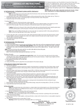
STARTING OUT
Adjustment
Adjustment
Lever Reach Adjustment
Banjo Assembly
Banjo
Disc Screw Torqueing Sequence
BRAKE PAD REMOVAL
BLEEDING THE SYSTEM
C
A
B
3
2
4
45-21883Web page 7
1

13
14
15
16
17
18
19
20
20
10
12
11
# Kit Description
Master Cylinder
1 Complete Master Cylinder Assembly
(includes items 2-9)
2 Lever Blade
3 Master Cylinder Body
4 Clamp/Screw Kit
5 Reservoir Kit
6 Lever Pivot Kit
7 Push Rod Kit
8 Bleed Kit
9 Internal Kit
Hose
10 90cm Front Hose Kit
160cm Rear Hose Kit
11 Hose Insert and
Compression Bushing
12 Compression Nut
Caliper
13 Complete Caliper
14 Caliper Rebuild Kit
15 Piston Kit
16 Bridge Bolt
17 Transfer Port O-Ring Seal
18 Caliper Bleeder Fitting Kit
19 Brake Pad Kit
20 Brake Pad Pin Kit
2
1
3
4
5
6
7
8
9
5a
45-21883Web page 8

16
17
18
19
20
21
22
# Kit Description
Master Cylinder
1 Complete Master Cylinder Assembly.
Trail “Gray”, or “White”
(includes items 2-9)
2 Lever Blade
3 Master Cylinder Body
4 Clamp/Screw Kit
5 Reservoir Cap Kit
6 Lever Pivot Kit
7 Push Rod Kit
8 Bleed Screw
9 Internal Kit
Hose
10 90cm Front Hose Kit
160cm Rear Hose Kit
11 Hose Connection Seal
12 Hose Insert and
Compression Bushing
13 Compression Nut
14 Nose Cone
15 Banjo Bolt
Caliper
16 Complete Caliper
17 Caliper Rebuild Kit
18 Piston Kit
19 Bridge Bolt
20 Transfer Port O-Ring Seal
21 Caliper Bleeder Fitting Kit
22 Brake Pad Kit
2
1
3
4
5
6
7
8
9
5b
10
12
13
14
11
15
45-21883Web page 9
Hayes Bicycle Group
5800 W. Donges Bay Rd. Mequon, WI 53092
Technical Assistance Line 1-888-686-3472
www.hayesdiscbrake.com
Copyright 2008 Hayes Bicycle Group
/