Page is loading ...

SAFETY NOTES
Please read this manual carefully before attempting to install or operate the Access Control
equipment.
This equipment must be installed in line with all relevant regulations and standards.
Make sure that wiring is rated according to fuses and current limits of relevant power supplies.
All connections to this unit must be SELV level. (Safety Extra Low Voltage, BS EN 60950 1992)
Every effort is made to ensure that this manual is complete and free from errors. However we
reserve the right to make changes to these products and this manual without notice.
No liability is accepted for loss damage or injury as a consequence of using these products or
instructions.
These products are not designed for use in life support or safety critical appliances or systems
where malfunction of these products can reasonably be expected to result in personal injury.
Customers using or selling these products for use in such applications do so at their own risk
EMC, LV and
RTTE
Certificate Number 17851
Document Number: 3802-I01 Issue 05
Copyright BSB Electronics Ltd 2007,2008, all rights reserved.
HARDWARE MANUAL

Contents
Contents __________________________________________________________ 2
System Overview _________________________________________________ 1
FORTESSA Controller _____________________________________________ 2
Description _____________________________________________________________ 2
Box Contents ____________________________________________________________ 2
Mounting _______________________________________________________________ 2
Lock Drive ______________________________________________________________ 3
Readers ________________________________________________________________ 3
Inputs __________________________________________________________________ 3
Resetting to Factory Defaults _______________________________________________ 3
Supply _________________________________________________________________ 3
Network ________________________________________________________________ 3
Cable __________________________________________________________________ 3
Network ______________________________________________________________ 3
Reader _______________________________________________________________ 4
LEDs __________________________________________________________________ 4
Status ________________________________________________________________ 4
Reader (A & B) ________________________________________________________ 4
Network LEDS ________________________________________________________ 4
Relay ________________________________________________________________ 4
Fire__________________________________________________________________ 4
Intruder ______________________________________________________________ 4
Notes on the Fire and Intruder Short Circuit Detector LEDs ________________________ 4
FORTESSA Reader (Switch Plate Style) _____________________________ 5
Box Contents ____________________________________________________________ 5
Description _____________________________________________________________ 5
Power __________________________________________________________________ 5
Mounting _______________________________________________________________ 6
Connections _____________________________________________________________ 6
Inputs __________________________________________________________________ 6
Door Sensor ___________________________________________________________ 6
Request to Exit _________________________________________________________ 6
Locking Device ________________________________________________________ 6
LEDs __________________________________________________________________ 7

FORTESSA Reader (Mullion Style) _________________________________ 8
Box Contents ____________________________________________________________ 8
Description _____________________________________________________________ 8
Mounting _______________________________________________________________ 8
FORTESSA Touch Switch _________________________________________ 9
Description _____________________________________________________________ 9
Box Contents ____________________________________________________________ 9
Power _________________________________________________________________ 10
Mounting ______________________________________________________________ 10
Connections ____________________________________________________________ 10
LED ________________________________________________________________ 10
BUZ ________________________________________________________________ 10
CONTACT __________________________________________________________ 11
LED’s ________________________________________________________________ 11
FORTESSA USB Interface ________________________________________ 13
Description ____________________________________________________________ 13
Box Contents ___________________________________________________________ 13
Mounting ______________________________________________________________ 13
Connections ____________________________________________________________ 13
Cables ________________________________________________________________ 14
Desktop Reader _________________________________________________________ 14
LED Indicators _________________________________________________________ 14
The Reader LEDs _____________________________________________________ 14
The USB LEDs _______________________________________________________ 14
The FORTESSA Network LEDs __________________________________________ 14
FORTESSA Credentials __________________________________________ 16
Proximity Card _________________________________________________________ 16
Proximity Key Fob ______________________________________________________ 16
Proximity Sticky Dot _____________________________________________________ 16
FORTESSA Product Codes _______________________________________ 16

FORTESSA.net __________________________________________________ 17
Programming ___________________________________________________________ 17
Keyboard ____________________________________________________________ 17
Functions ____________________________________________________________ 18
Set FORTESSA.net IP Address ___________________________________________ 18
Set Server IP Address Filter (Optional) _____________________________________ 18
Controller / Door Name Table _____________________________________ 18

1
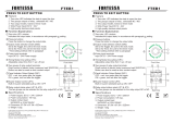
System Overview
Figure 1

2
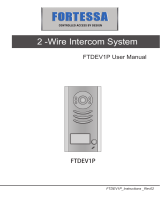
FORTESSA Controller
Description
The FORTESSA and FORTESSA.net Controllers are single door controllers for use
with the FORTESSA access control range. FORTESSA uses a revolutionary reader
interface that allows most door functions to be handled over a single 4 core
unscreened cable. The controller is completely programmed from a PC using the
Doors Express software.
Figure 2
Box Contents
1 x FORTESSA Controller or FORTESSA.net Controller mounted in a 165mm
x 145mm steel enclosure (black)
1 x Hardware Manual
Mounting
The FORTESSA Controller and its power supply should be mounted in a secure
location or on the secure side of the door. This should ideally be as close to the door
as possible (Max 100m cable run) to avoid volt drops.

3
Lock Drive
There are two voltage free relays (A & B) on the FORTESSA Controller for operating
locking devices.
Readers
The controller has 2 proximity reader channels for use with FORTESSA readers only.
Reader A is designated out and Reader B is designated in.
Inputs
The FORTESSA Controller has four input terminal blocks for external devices:
a door sensor input (DR),
a Request to Exit input (RQE),
an Intruder input for connecting to an alarm panel and,
a Fire input for connecting to a fire panel.
Resetting to Factory Defaults
The controller can be reset to factory defaults by pressing and holding the reset button
located at the bottom right of the board for 7 seconds.
Supply
The FORTESSA Controllers require a 12V DC PSU (not supplied). The actual
operating range is between 10V DC and 14V DC.
Network
Figure 1 shows both USB and Ethernet connectivity options to the FORTESSA
controller from a host PC. The upper part of Figure 1 shows the 3801 FORTESSA
Controller using the 3803 FORTESSA USB Interface
The lower part of Figure 1 shows connectivity to the 3802 FORTESSA.net Controller
using a LAN or WAN.
Additional 3801 FORTESSA Controllers can be added to the system by linking them
together in a daisy chain using the FORTESSA Network. Doors Express will support a
maximum of 16 controllers per system.
The End of Line Resistor jumper is set to N as default. This should be changed to Y if
the FORTESSA Controller is the first or last controller on the daisy chain network.
Cable
Network
Two core twisted pair cable is to be used to wire the FORTESSA Network (a screened
cable can be used to offer better protection).
If the optional screened cable is used then the incoming and outgoing screen can be
fitted to SCR on the Network terminal block. It is important to remember that the
screen needs to be earthed to ground at one end of the network.

4
Reader
The FORTESSA Readers are connected to the FORTESSA Controller using a
standard 4 core cable (alarm cable is suitable).
LEDs
Status
The status LED next to the reset button indicates whether the board has power or not.
Reader (A & B)
The readers LEDs indicate whether the reader circuit is in overload (red) or if there is
activity from the reader itself (green).
Network LEDS
The green LED signifies that data has been received by the controller and the red LED
indicates that there is traffic on the FORTESSA Network.
Relay
The green LEDs illuminate when the relays have been activated.
Fire
The red LED is on when there is a short on the Fire circuit and the green LED is on
when it is in a state of alarm.
Intruder
The red LED is on when there is a short on the Intruder circuit and the green LED is on
when it is in a state of alarm.
Notes on the Fire and Intruder Short Circuit Detector LEDs
The controller comes fitted with resistors between the I/P and 0V terminal blocks on
both the Fire and Intruder inputs. To enable the board to detect a short on either circuit
when fitting to a fire or alarm panel the resistor should be moved to the fire or alarm
panel terminal block output.

5
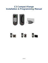
FORTESSA Reader (Switch Plate Style)
Front View of FORTESSA Reader
Figure 3
Box Contents
1 x FORTESSA Reader
1 x stainless steel facia
1 x UK standard surface mount single gang back box
2 x security screws
1 x driver bit for security screws
Description
The FORTESSA Reader is a passive RFID (Radio Frequency Identification) proximity
reader for use with the FORTESSA system. The FORTESSA Reader is weather
protected to IP66 and suitable for both indoor and outdoor use.
Power
The FORTESSA Reader uses 12V DC and power is taken from the positive and
negative connections of the Reader terminal block on the FORTESSA Controller
board.

6
Mounting
Figure 4
Connections
The FORTESSA Reader should be connected to the FORTESSA Controller using a
four core cable. The cable run should be no more than 100 metres. Data is
transferred between the FORTESSA Reader and FORTESSA Controller through the
respective X and Y terminal blocks and should be linked X to X and Y to Y.
Inputs
Door Sensor
A door contact sensor can be fitted to DR on the Door terminal block and the negative
terminal should be wired in to the negative connection on the Reader terminal block.
Request to Exit
A normally open connection, or “push to make” connection, Request to Exit button may
also be fitted to the FORTESSA Reader. The positive of the RQE should be wired in to
RQE on the Door terminal block and the negative should be wired in to the negative of
the Reader terminal block. The FORTESSA reader must be fitted to Reader A on the
FORTESSA Controller and the RQE feature enabled in Doors Express for this
configuration to work
Locking Device
A small strike lock can also be fitted to the reader with a rating of no more than 100mA
by wiring in to the positive and negative Lock terminal block on the FORTESSA
Reader.

7
LEDs
There are two bi-colour LEDs on the reader. The lower LED flashes red until a
credential is present when it will stay red and hold until the proximity credential is
removed. The upper LED will turn green when a valid card is presented to the reader
and red when the card is invalid.
Figure 5

8
FORTESSA Reader (Mullion Style)
Front View of FORTESSA Reader
Box Contents
1 x FORTESSA Reader
1 x stainless steel facia
2 x security screws
1 x driver bit for security screws
Description
The FORTESSA Reader is a passive RFID (Radio Frequency Identification) proximity
reader for use with the FORTESSA system. The FORTESSA Reader is weather
protected to IP66 and suitable for both indoor and outdoor use.
Mounting
Drill a 6mm hole at the centre point of the mounting position for the cable. The two
mounting holes are on a 80mm pitch vertically from that point. Drill and plug the wall for
a Number 6 screw. Feed the cable through the 6mm hole and secure the reader / front-
plate with the screws provided.
Cable Colour
Connection
Red
+
Yellow
Y
Green
X
Black
-
Orange
LOCK +
Violet
LOCK -
Blue
DR
Brown
RQE

9
FORTESSA Touch Switch
Description
The FORTESSA Touch Switch is capable of detecting near-proximity or touch. It
projects a touch proximity field through the dielectric of the enclosure. The patented
spread-spectrum charge-transfer technology, coupled with its ability to self-calibrate,
makes this an entirely new concept.
It is designed specifically for “Request to Exit” or “Request to Enter Call” applications.
The fully sealed IP66 enclosure makes it suitable for internal or external use.
Figure 6
Box Contents
1 x FORTESSA Touch Switch
1 x UK standard surface mount single gang back box
2 x screws
FORTESSA
READER
FORTESSA
READER

10
Power
The FORTESSA Touch Switch uses 12V DC and power is taken from the positive and
negative connections of the Reader terminal block on the FORTESSA Controller
board. The supply may also be tapped from a nearby FORTESSA reader.
Mounting
The touch switch may be mounted using the surface box provided or for better
aesthetic appearance use a flush back box.
Figure 7
Connections
The touch switch may be connected to the system in one of two ways:
Directly to the FORTESSA controller
To a nearby proximity reader (Piggy Backed)
The piggy back option should only be used where the hacker attack is not a concern.
For security reasons never use this option with external readers.
A four core unscreened cable should be sufficient for either wiring method. Wiring
diagrams for the two methods are shown on the following pages. The cable run should
be no more than 100 metres.
LED
This input will light the top Green LED when it is connected to 0V.
BUZ
When this input is shorted to 0V the inbuilt sounder will beep.

11
CONTACT
The relay contact of the switch provides C, NC and NO connections. The relay
contacts changeover when the surface of the switch is touched. This change over is
timed so that it will not hold even if the triggering object is not removed from the
surface.
Figure 8
LED’s
There are two bi-colour LED’s on the reader. The lower LED flashes red until the front
surface of the switch is touched. The LED will then stay green until the hand or finger is
removed. The upper LED is controlled from the LED input.

12
Figure 9

13
FORTESSA USB Interface
Description
The FORTESSA USB Interface allows data to be transferred from a host PC to the
FORTESSA controllers.
Figure 10
Box Contents
1 x FORTESSA USB Interface
1 x UK standard surface mount single back box
1 x 3 metre USB lead
2 x screws
Mounting
The USB Interface cannot be fitted on a flush mounted back box and should be
mounted on the special surface mount back box which is provided.
Connections
The USB cable is connected from the host PC using the USB socket at the bottom of
the FORTESSA USB Interface (before connecting the device for the first time it is
important to start Doors Express first which will complete the driver installation).
The FORTESSA USB Interface is powered through a USB cable from the PC and does
not require a separate power supply. The green flashing LED on the PCB on the rear
of the FORTESSA USB Interface gives an indication as to whether the board is
receiving power.
The FORTESSA USB Interface should be connected to a FORTESSA Controller by
linking the Network A and B terminal block on the FORTESSA USB Interface to the
Network A and B terminal block on the FORTESSA Controller.

14
End of Line Resistor
The End of Line resistor should be set to Y on the jumper setting (see figure 11).
Cables
Two core twisted pair cable is to be used to wire the FORTESSA Network (a screened
cable can be used to offer better protection). FORTESSA Controllers can be further
linked together in a “daisy chain”, to a maximum of 16 on the whole network, by wiring
A to A and B to B using the Network terminal blocks of the FORTESSA Controllers.
If the optional screened cable is used then the incoming and outgoing screen can be
fitted to SCR on the Network terminal block. It is important to remember that the
screen needs to be earthed to ground at one end of the network.
A screened cable has advantages over a standard twisted pair cable. Whilst not a
complete guarantee, a correctly fitted screened cable will help protect against induction
from fluorescent lighting, power surges or lightening strikes by safely discharging the
current to earth instead of the circuit board which could lead to damage.
Desktop Reader
The USB Interface can also support a connection to a FORTESSA Desktop Reader
which is connected via the Reader terminal block. The positive and negative terminals
from the FORTESSA Desktop Reader should be wired to the positive and negative
connections on the USB Interface Reader terminal block and the X and Y data
connections from the FORTESSA Desktop Reader should be wired to the USB
Interface Reader terminal block by linking X to X and Y to Y.
Figure 7 below shows the layout of the USB Interface including the network
connections and desktop reader ancillary.
LED Indicators
The Reader LEDs
The LEDs inform on the status of the optional FORTESSA Desktop Reader. A red
LED indicates that there is a short circuit and a green LED indicates that there is data
from the desktop reader.
The USB LEDs
TX (red) and RX (green), advise on whether the PC is transmitting to the USB Interface
(TX) or receiving information from the USB Interface (RX).
The FORTESSA Network LEDs
The green Poll LED signifies that the USB Interface is receiving data from the PC and
the red Data LED signifies that there is data on the FORTESSA network.

15
Figure 11

16
FORTESSA Credentials
Proximity Card
The FORTESSA Proximity Card is a passive RFID ISO proximity card for use with
FORTESSA systems only. The card is credit card size and thickness and can be
comfortably stored in a wallet or purse. The ISO proximity card is suitable for card
printing enabling the card to also serve as an identity card.
Proximity Key Fob
The FORTESSA Proximity Key fob is a passive RFID proximity credential which
conveniently fits on a key ring which is ideal for people who forget their cards, wallets
or purses but remember their car and house keys! The FORTESSA Key Fob is for use
with FORTESSA systems only.
Proximity Sticky Dot
The FORTESSA Proximity Sticky Dot is a passive RFID proximity credential which can
be attached to the rear of mobile phones or other hand held devices. The dots are
ideal if you wish to use existing identity cards as credentials for access, simply attach a
dot to the rear of the identity card. The FORTESSA Proximity Sticky Dots are for use
with FORTESSA systems only.
FORTESSA Product Codes
3800-FT
FORTESSA Reader
3801-FT
FORTESSA Controller
3802-FT
FORTESSA.net Controller
3803-FT
FORTESSA USB Interface
3804-10
FORTESSA ISO Proximity Card (10 Pack)
3804-100
FORTESSA ISO Proximity Card (100 Pack)
3805-10
FORTESSA Proximity Key fob (10 Pack)
3805-100
FORTESSA Proximity Key fob (100 Pack)
3806-10
FORTESSA Proximity Sticky Dot (10 Pack)
3806-100
FORTESSA Proximity Sticky Dot (100 Pack)
3808-FT
Doors FORTESSA Software
3809-FT
Doors FORTESSA Pro Software
3068-FT
FORTESSA Touch Switch
3811-FT
FORTESSA Demo Case (USB)
3812-FT
FORTESSA Demo Case (.net)
/