Page is loading ...

PRESS TO EXIT BUTTON
1. Two-color LED indicates the state to open the door
2. Two groups of relay , selectable NC / NO
3. Two output modes, locked or timer mode
4. Wide Power Input DC12 ~ 24V
5. High-quality stainless steel panels
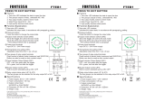
outputs
Pressure buttons
Press the button to change the output state
2
Output mode selection switch (SW2)
Set to the Toggle, the unit for the lock mode.
to the Timer, the unit for the timer mode.
*Time setting method refer to paragraph
Set
3
Power input terminals
Input DC12 ~ 24V Power supply
4
Timing Mode time setting (VR1):
Adjustable output time from 1 sec -30 sec
5
Two groups of relay output terminals
Direct control of electric locks (maximum load 30VDC/2A)
Button can also be used as door contact output.
6
Panel Indicator Output Select (SW1)
OFF = red, green after the trigger.
ON = green, turn red after the trigger.
turn
7
Buzzer Output Control (JP3)
Built-in buzzer selectable pull-up ON / OFF
8
Relay output status select (JP1 & JP2)
The two groups can be selected for the relay output NC or NO.
9
5
Function Explaination
Specifications
FTEB3
1
2
4
3
5
6
7
8
9
JP3
NC
NO
CON1
DC12-24V
OUT1 OUT2
ON
OFF
1S
30S
VR1
Timer
Toggle
SW2
JP2
NC
NO
JP1
CON2
SW1
1. Power Supply: DC12 ~ 24V / 200mA
2. Power consumption: 1W max.
3. Output contact load:
2A/30VDC or 0.5A/125VAC
4. : 43W x 115H x 32Dmm
5. Weight: 90g
Dimension
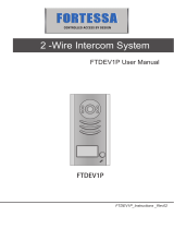
PRESS TO EXIT BUTTON
Feature Feature
1. Two-color LED indicates the state to open the door
2. Two groups of relay , selectable NC / NO
3. Two output modes, locked or timer mode
4. Wide Power Input DC12 ~ 24V
5. High-quality stainless steel panels
outputs
Two-color LED window
Indicates the output state, in accordance with paragraph setting.
1
7
Two-color LED window
Indicates the output state, in accordance with paragraph setting.
1
7
Pressure buttons
Press the button to change the output state
2
Output mode selection switch (SW2)
Set to the Toggle, the unit for the lock mode.
to the Timer, the unit for the timer mode.
*Time setting method refer to paragraph
Set
3
Power input terminals
Input DC12 ~ 24V Power supply
4
Timing Mode time setting (VR1):
Adjustable output time from 1 sec -30 sec
5
Two groups of relay output terminals
Direct control of electric locks (maximum load 30VDC/2A)
Button can also be used as door contact output.
6
Panel Indicator Output Select (SW1)
OFF = red, green after the trigger.
ON = green, turn red after the trigger.
turn
7
Buzzer Output Control (JP3)
Built-in buzzer selectable pull-up ON / OFF
8
Relay output status select (JP1 & JP2)
The two groups can be selected for the relay output NC or NO.
9
5
Function Explaination
FTEB3
1
2
3
4
5
6
7
8
9
JP3
NC
NO
CON1
DC12-24V
OUT1 OUT2
ON
OFF
1S
30S
VR1
Timer
Toggle
SW2
JP2
NC
NO
JP1
CON2
SW1
1. Power Supply: DC12 ~ 24V / 200mA
2. Power consumption: 1W max.
3. Output contact load:
2A/30VDC or 0.5A/125VAC
4. : 43W x 115H x 32Dmm
5. Weight: 90g
Dimension
Specifications
FORTESSA distributed by CHALLENGER SECURITY PRODUCTS
10 Sandersons Way,
Blackpool, FY4 4NB
Tel :01253 791888 Fax:01253 791887
Email: [email protected]
Website: www.challenger.co.uk
FORTESSA distributed by CHALLENGER SECURITY PRODUCTS
10 Sandersons Way,
Blackpool, FY4 4NB
Tel :01253 791888 Fax:01253 791887
Email: [email protected]
Website: www.challenger.co.uk
/