Page is loading ...

MH
SYSTEMTWOSURGICALLIGHTINGSYSTEM
INSTALLATIONAND
SERVICEMANUAL
MEDICALILLUMINATIONINTERNATIONALINC.
W HERE ILLUMINATION IS DEFINED

System Two MH Surgical Lighting System Service Manual (1002156) Page 1
MH
Agency Approvals
Medical Electrical Equipment
With respect to electric shock, fire
And mechanical hazards only
In accordance with UL60601-1:2006 / CAN/CSA C22.2 No.601.1-M90 with updates 1 & 2.
Classifications:
1. Protection against electrical shock (5.1, 5.2). Class I permanently connected,
2. Protection against harmful ingress of water (5.3). None.
3. Degree of safety in the presence of flammable anesthetics or oxygen (5.5). Not suitable
for use in the presence of flammable anesthetics or oxygen.
4. Mode of operation (5.6). Continuous.
5. Surgical luminaries (IEC60601-2-41) Minor.
Electromagnetic compatibility for immunity
And emissions in accordance with
EN-60601-1-2(2001) Class B and CISPR 22 (1997) Class B
Medical Electrical Equipment
Particular requirements for the safety of surgical
luminaries and luminaires for diagnosis
In accordance with IEC-60601-2-41
Intended use
The System Two surgical lighting system is an AC powered device which provides
a focusable field of illumination for general examination and surgery.

System Two MH Surgical Lighting System Service Manual (1002156) Page 2
MH
Surgical Lighting System Installation and
Service Manual
Revisions
Revision
letter ECO
number Pages Affected Date
A 1117 Initial Release 1/6/10

System Two MH Surgical Lighting System Service Manual (1002156) Page 3
Table of Contents
Section 1: Terminology
Definition of terms
List of Symbols
Section 2: Specifications
Mechanical Specifications
Electrical Specifications
Optical Specifications
Environmental Specifications
Floor Mount Specifications
Warranty
Section 3: Installation
Pre-installation Guidelines
Solo Ceiling Mount Installation
Duo Ceiling Mount Installation
Trio Ceiling Mount Installation
Floor Mount Installation
Section 4: Operating Instructions
Light Head Position Adjustment (arm operation)
Turning Light Head on/off
Light Pattern Dimming Function
Light Pattern Adjustment
Section 5: Safety Instructions
General Safety Instructions
Section 6: Maintenance
Lamp Replacement
Fuse Replacement
Arm Tension Adjustment
Head Friction Adjustment
Arm/Head Friction Adjustment
Handle Sterilization
Cleaning Instructions
Maintenance Schedule

System Two MH Surgical Lighting System Service Manual (1002156) Page 4
Table of Contents (Continued)
Section 7: Troubleshooting
General Trouble Shooting
Section 8: Exploded Views and Parts List
Electrical Schematic
Ballast Assembly
Ceiling Casting Assembly
Ceiling Rod Assembly
Arm assembly
Light head assembly
Extension/Adapter
Solo Assembly
Duo Assembly
Trio Assembly

System Two MH Surgical Lighting System Service Manual (1002156) Page 5
List of Figures
Figure Number and Description Page
Number
Figure 1- Mounting Dimensions for Ceiling Casting 14
Figure 2- Ceiling Rod Calculation Solo Ceiling Mount 15
Figure 3- Ceiling Rod Calculation Duo Ceiling Mount 16
Figure 4-Ceiling Rod Calculations Trio Ceiling Mount 17
Figure 5- Sub-assemblies for Solo Ceiling Mount
Figure 6- Ceiling mount
18
19
Figure 7- Unpacking
Figure 8- Installation setup
20
21
Figure 9- Arm and ceiling assembly
Figure 10- Ceiling & Shaft Dowel Pin insertion
Figure 11- Ceiling & Shaft Dowel Pin locking
Figure 12- Arm cable termination
23
24
25
26
Figure 13- Locking Pin Removal 27
Figure 14- Floor Mount Dimensions 28
Figure 15- Floor Stand Light Installation 29
Figure 16- Arm Assembly to Upright Pole Installation 31
Figure 17- System Two Head and Arm Movements 32
Figure 18- Floor Stand and Arm Movements
Figure 19-Lamp Replacement
33
37
Figure 20-Fuse Replacement 38
Figure 21-Arm Adjustment 39
Figure 22-Light Head Friction Adjustment 40
Figure 23- Arm Friction Adjustment 41
Figure 24- Handle Sterilization 42

System Two MH Surgical Lighting System Service Manual (1002156) Page 6
Section 1
Definition of Terms
I.E.C.
International Electrotechnical Commission
TUV
TUV SUD America
Medical Electrical Equipment
Electrical equipment intended to diagnose, treat the patient under medical supervision.
Electrical equipment that transfers energy to the patient.
Central Illuminance
Illuminance of light head measured at 1 meter from the light emitting area with no
obstructions. Expressed in Foot-candles or Lux.
Light Field Center
Point of maximum illuminance in lighted area. This is the reference point for light field
size and light distribution measurements.
Light Field Diameter
Diameter of the circle where illuminance reaches 10% of light field center illuminance.
Depth of Illumination
The overall distance from 1 meter where the central Illuminance is reduced to 20%.
Shadow Dilution
Ability of the equipment to minimize the impact of shadows in the working area due to
partial obstruction by the operator or other medical personnel.
Correlated Color Temperature
The color temperature of the light fixture when compared to a blackbody radiator
expressed in degrees Kelvin.
Total Irradiance
The total amount of energy imparted to the patient by the lighting system expressed in
Watts/meter squared.
Color Rendering Index (CRI)
A method of how well a light source will render other colors when illuminating them based
upon eight CIE chromaticity coordinates measured with a spectroradiometer.
Handle Sterilizable
Device when properly sterilized maintains a sterile area in order to handle it under aseptic
conditions when attached to the equipment

Surgical Lighting System Surgical Lighting System Service Manual (1002156)
Page 7
Section 1
Definition of Terms (continued)
Light Head/Articulating Arm Assembly:
That part of the device which includes the light source, heat removal system, light
focusing system and light head vertical positioning arm.
Extension Arm
Horizontal section of the positioning arm with pivots on both ends that is used to increase
the area covered by the light head and articulating arm.
Light Mounting
Support apparatus used to connect light head/articulating arm assembly to a fixed
surface, consisting of either a single, double or triple ceiling mount.
Neutral Conductor
In an AC circuit, the return line for current.
Protective earth ground
The conductor used to connect the non-current-carrying metal parts of equipment,
raceways, and other enclosures to the system grounded conductor, the grounding
electrode conductor, or both, of the circuit at the service equipment or at the source of a
separately derived system.
Ft-Lbs
Foot-pounds. The unit of measurement of torque which is caused by an off-center load.

Surgical Lighting System Surgical Lighting System Service Manual (1002156)
Page 8
Section 1
List of symbols
TUV Listing marking
Read accompanying documents
C.E. Marking
Fuse marking
Protective earth ground
Neutral conductor
Caution
Electric shock hazard
Primary Bulb Life indicator
Primary Bulb Life Clock Reset button
Light head on/off button

Surgical Lighting System Surgical Lighting System Service Manual (1002156)
Page 9
Section 2
Specifications
Mechanical
Parameter Value
Weight
Solo ceiling mount assembly
Duo ceiling mount assembly
Trio ceiling mount assembly
Light head assembly
Approximately 73.5 lbs (33.3 Kg).
Approximately 104.5 lbs (47.4 Kg).
Approximately 155.5 lbs (70.5 Kg).
Approximately 23.5 lbs (10.7 Kg).
Dimensions
Ceiling casting
Ceiling rod (See fig’s 2,3 & 4)
Arm (articulated)
Light head assembly
17.0” (431.8 mm) Dia x 4.7” (119.4 mm) deep
2.5” (63.5 mm) Dia x 9.0”-43.0”(228.6 -1092.2 mm)
long (depending on ceiling height)
3.5” (88.9 mm) Dia(tapered) x 26 0“ (660.4 mm) long
23.0” (584.2 mm) diameter x 10.0” (254mm) deep
Rotations
Ceiling mount/extension arm interface
Articulating/extension arm interface
Articulating arm vertical movement
Articulating arm/Yoke interface
Yoke/lamp head interface
Continuous
Continuous
+20, -70 Degrees
Continuous
+/- 150 Degrees
Electrical
Parameter Value
Voltages
Input Voltage
Lamp voltage
100 - 125 VAC 50/60 Hz
220 - 240 VAC 50/60 Hz
120 VAC 50/60 Hz (39 Watts) Primary
24 – VAC 50/60 Hz (80 Watts) Secondary
Bulb life 10,000 hours (average) For Primary
Power
Solo (SS2120 MH, SS2230 MH)
Duo (SS2S2120 MH, SS2S2230 MH)
Trio (SS2S2S2120 MH, SS2S2S2230
MH)
120/230 VAC, 50/60 Hz 140 Watts
120/230 VAC, 50/60 Hz 280 Watts
120/230 VAC, 50/60 Hz 420 Watts

Surgical Lighting System Surgical Lighting System Service Manual (1002156)
Page 10
Section 2
Specifications
Optical
Parameter Value
Reflector
20” (508mm) diameter polished aluminum, facetted
IR/Color correcting filter glass
Corrected color Temperature
Irradiance
Color Rendering Index
4300 ° Kelvin
314 W/m2 (1m)
90
Parameter Value
Performance
Focal length
Central illuminance(adjustable)
Maximum illuminance @33”
Light field diameter(adjustable)
Depth of illumination
Diameter (d50)
Illuminance(one mask)
Illuminance(two masks)
Illuminance at bottom of standard tube
Illuminance at bottom of standard tube
with one mask
Illuminance at bottom of standard tube
With two masks
39” (1 meter)
2,500- 9,290 foot-candles (26,909 -100,000 Lux)
10,500 foot-candles (113,018 Lux)
5.62 - 9.85” (143 - 250mm)
48” (1,220mm)
4.12” (105mm)
2,735 foot-candles (29.500 Lux)
4,126 foot-candles (44,500 Lux)
9,829 foot-candles (106,000 Lux)
2,875 foot-candles (31,000 Lux)
4,312 foot-candles (46,500 Lux)
Environmental
Parameter Value
Operating temperature 41 - 104 deg F (5-40 Degrees Celsius)
Storage temperature Range 41 - 104 deg F (5-40 Degrees Celsius)
Humidity 10 - 90% relative humidity

Surgical Lighting System Surgical Lighting System Service Manual (1002156)
Page 11
Section 2
Specifications (Floor Model)
Mechanical
Electrical
Parameter Value
Power
FS2120 MH,
FS2230 MH,
120 VAC, 50/60 Hz, 140 Watts
230 VAC, 50/60 Hz, 140 Watts
Parameter Value
Weight
Floor base with upright.
Arm assembly
MH Light Head
Approximately 88.5 lbs (40,1 Kg)
Approximately 16.3 lbs (7,4 Kg)
Approximately 23.5 lbs (10.7 Kg)
Dimensions
Floor base
Upright
Arm assembly
7.5” (190,5 mm) high x 28” (711,2 mm) long x 25”
wide (635 mm)
2.5” (63,5 mm)Dia 79” (2006,6 mm)
3.5” (88,9 mm) Dia (tapered) x 26.0” (660,4 mm) long
Rotations
Articulating arm interface vertical
movement
Articulating arm/upright interface
horizontal movement
+20 Degrees, 70 Degrees
+/- 7.5 Degrees

Surgical Lighting System Surgical Lighting System Service Manual (1002156)
Page 12
Section 2
Medical Illumination International, Inc.
Lighting Equipment
Limited Warranty
Medical Illumination International, Inc. Lighting Equipment is warranted against defective material and/or
workmanship, excluding normal replacement parts (e.g. bulbs or glass items), for a period of three (3) years from
the date of shipment. This warranty applies exclusively to the repair or replacements of parts recognized as
defective by Medical Illumination International, Inc., are in normal use, and have not been modified or repaired by
unauthorized personnel. This warranty supersedes all other guarantees or warranties, expressed or implied.
In the event of a failure covered under this warranty, please take the following action:
1. Call the Medical Illumination Customer Service Department at (818) 838-3025.
Be prepared to give the model number, serial number, and full description of the failure.
Customer Service will attempt to solve the problem over the phone. If it becomes necessary to send the
product to the factory for repair, Customer Service will provide a Return Authorization number. No product
should be returned without a Return Authorization number.
2. Carefully package the light component (light head, arm assembly, or mount assembly) and return it, freight
prepaid and insured, with the Return Authorization number clearly marked on the box, to:
Medical Illumination International, Inc.
547 Library Street
San Fernando, CA 91340
RA#
Damage resulting from inadequate packing is not covered by this warranty and shipping insurance does not
cover damage from inadequate packing.
We recommend that the package be insured against loss or in-transit damage. Medical Illumination can not be
responsible for in-transit loss or damage.
3. DAMAGE TO THE PRODUCT RESULTING FROM TAMPERING, ACCIDENT, ABUSE, NEGLIGENCE, OR
OTHER CAUSES UNRELATED TO PROBLEMS WITH MATERIAL AND/OR WORKMANSHIP, ARE NOT
COVERED BY THIS WARRANTY.
4. Warranty may be voided if equipment is found to have been installed incorrectly, resulting in equipment failure.
5. This warranty does not cover any labor costs associated with removing, re-packaging for shipment or
reinstalling this product. Such costs are the responsibility of the purchaser.
6. Medical Illumination International, Inc. will evaluate the returned product, repair as appropriate, and ship the
product back to you freight paid.
7. In the event non-warranty damage or failure is discovered, you will be contacted before repairs are performed.

Surgical Lighting System Surgical Lighting System Service Manual (1002156)
Page 13
Section 3
Pre-Installation Guidelines
SPECIAL NOTE: Installation and repair of this equipment should be performed by
qualified persons only. Medical Illumination International, Inc. does not warranty any
damage occurring as a result of improper installation.
It is recommended that this installation manual be completely reviewed prior to
installation.
Before installation, check to insure the following minimum conditions are provided:
• The structural ceiling mount is designed to support a vertical load of 230 lbs and an off
center moment of 600 ft-lbs. The structural mount should meet all local building codes.
A structural mount that does not meet these minimum conditions can cause serious
injury and/or property damage.
• Use the template provided to drill the four mounting holes for the ceiling casting sub-
assembly. If these are going to be through holes drill 7/16” diameter holes. If these will be
threaded holes use hole size consistent with fastener being used.
• It is recommended that the System Two surgical lighting system be mounted directly over a
4-0 junction box. If this is not possible the input power supply lines should be wired in
accordance with all applicable building codes.
• The supply circuit line must be as follows:
120 VAC lights-110-120 VAC 50/60 Hz, single phase, three wire, capable of supplying 420
watts @ 4 amperes.
230 VAC lights- 220-240 VAC, 50/60 Hz, single phase, three wire, capable of supplying 420
watts @ 2.0 amperes.
• The power supply circuit must be in compliance with all applicable building codes.
• The light head switches secondary transformer power only. It is recommended that the
System Two Surgical Lighting System is connected to its own supply circuit with integral
circuit breaker. The circuit breaker will act as the supply main disconnect switch.
Failure to provide a circuit meeting these minimum standards or complying with
local building codes can cause a shock hazard.
• Check the length of the ceiling rod supplied to make sure that it is the proper length to
install and operate the light without interference or over reach. (See ceiling Rod
Calculation Pages 15-17).

Surgical Lighting System Surgical Lighting System Service Manual (1002156)
Page 14
Section 3
Pre-Installation Guidelines
Figure 1: Mounting Dimensions for Ceiling Casting (Top View)
[Dimensions with brackets are in millimeters]

Surgical Lighting System Surgical Lighting System Service Manual (1002156)
Page 15
“Y” VALUE
(DISTANCE TO FLOOR)
Section 3
Ceiling Rod Calculation
Solo Mount
Use the following table to select the correct length ceiling rod for your application (See Figure 2).
Ceiling
Mounting
Height
Ceiling Rod
Length “X” Value “Y” Value Head room to bottom
of extension arm
(y value-x value)
8’ (2,4m) N/A 18.25”(463,5mm) 96” 2.4m) 77.75” (1,974.8mm)
9’ (2,7m) 9.4” (238.7mm) 27.65” (702.3mm) 108” (2.7m) 80.35” (2,040.8mm)
9’ (2,7m) 13” (330.2mm) 31.25” (793.7mm) 108” (2.7m) 76.75” (1,949.4mm)
10’ (3,0m) 19” (482.6mm) 37.25” (964.1mm) 120” (3.0m) 82.75” (2,101.8mm)
10’ (3,0m) 25” (635.0mm) 43.25” (1,098.5mm) 120” (3.0m) 76.75” (1,949.4mm)
11’ (3,3m) 31” (787.4mm) 49.25” (1,250.9mm) 132” (3.3m) 82.75” (2,101.8mm)
12’ (3,6m) 43” (1092.2mm) 61.25” (1,555.7mm) 144” (3.6m) 82.75” (2,101.8mm)
Figure 2: Ceiling Rod Calculation Solo Mount
33” (838.2mm)
26” (660mm)
20°
70°
“X” VALUE
(TO BOTTOM OF EXTENSION ARM)
41” (1041.4mm)

Surgical Lighting System Surgical Lighting System Service Manual (1002156)
Page 16
Section 3
Ceiling Rod Calculation
Duo Mount
Use the following table to select the correct length ceiling rod for your application (See Figure 3).
Ceiling
Mounting
Height
Ceiling Rod
Length “X” Value “Y” Value Head room to
bottom of extension
arm
(y value-x value)
8’ (2,4m) N/A 23.25” (590.5mm) 96” (2,4m) 72.75” (1,847.8mm)
9’ (2,7m) 9.4” (238.7mm) 32.45” (829.3mm) 108” (2.7m) 75.35” (1,913.9mm)
9’ (2,7m) 13” (330.2mm) 36.25” (920.7mm) 108” (2.7m) 71.75” (1,822.4mm)
10’ (3,0m) 19” (482.6mm) 42.25” (1,073.1mm) 120” (3.0m) 77.75” (1,974.8mm)
10’ (3,0m) 25” (635.0mm) 48.25” (1,225.5mm) 120” (3.0m) 71.75” (1,822.4mm)
11’ (3,3m) 31” (787.4mm) 54.25”(1,377.9mm) 132” (3.3m) 77.75” (1,974.8mm)
12’ (3,6m) 43” (1092.2mm) 66.25”(1,682.7mm) 144” (3.6m) 77.75” (1,974.8mm)
“Y” VALUE
DISTANCE TO FLOOR
“X” VALUE
(TO BOTTOM OF EXTENSION ARM)
Fi
g
ure 3: Ceilin
g
Rod Calculation Duo Mount

Surgical Lighting System Surgical Lighting System Service Manual (1002156)
Page 17
25”(635mm)
Section 3
Ceiling Rod Calculation
Trio Mount
Use the following table to select the correct length ceiling rod for your application (See Figure 4).
Ceiling Mounting
Height Ceiling Rod
Length “X” Value “Y” Value Head room to bottom
of extension arm
(y value-x value)
8’ (2,4m) N/A 28.25” (717.5mm) 96” (2,4m) 67.75” (1,720.8mm)
9’ (2,7m) 9.4” (238.7mm) 37.65” (956.3mm) 108” (2,7m) 70.35” (1,786.9mm)
9’ (2,7m) 13” (330.2mm) 41.25” (1,047.7mm) 108” (2,7m) 66.75” (1,695.4mm)
10’ (3,0m) 19” (482,6mm) 47.25” (1,200.1mm) 120” (3,0m) 72.75” (1,847.8mm)
10’ (3,0m) 25” (635.0mm) 53.25” (1,352.5mm) 120” (3,0m) 66.75” (1,695.4mm)
11’ (3,3m) 31” (787,4mm) 59.25” (1,504.9mm) 132” (3,3m) 72.75” (1,847.8mm)
12’ (3,6m) 43” (1092,2mm) 71.25” (1,809.7mm) 144” (3,6m) 72.75” (1,847.8mm)
Fi
g
ure 4: Ceilin
g
Rod Calculation Trio Mount
25”(635 mm)
“Y” VALUE
DISTANCE TO FLOOR
41” (1041.4mm)
25”(635mm)
“X” VALUE
(TO BOTTOM OF EXTENSION ARM)

Surgical Lighting System Surgical Lighting System Service Manual (1002156)
Page 18
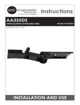
Section 3
GENERAL INFORMATION
The ceiling mounted, orbital lighting system is offered in three arm configurations, Solo, Duo &
Trio, (shown below as Solo). The system is shipped in separate cartons. The ceiling casting
assembly, hardware kit and this manual are in one carton. The arm assembly and ceiling
rod/adapter assembly are in one carton. The head assemblies are located in individual cartons.
Note: There are 6 standard length extension rods for different ceiling heights. Verify that
your ceiling rod length is correct for your ceiling height (See Pages 15-17).
Note: Ceilings under 8 ½ feet do not require an extension rod and adapter. If not correct
please contact customer service. For ceiling heights greater than 11 feet the ceiling rod/adapter
assembly will be shipped separately.
Prior to installation insure that all components shown in Figure 5 are present.
WHEN REMOVING PARTS FROM THE SHIPPING CARTONS, BE CAREFUL NOT TO
DAMAGE THE COMPONENTS OR BREAK ANY GLASSWARE.
IMPORTANT: THOROUGHLY CHECK EACH BOX FOR PARTS THAT MAY BE LOCATED
IN AREAS THAT CAN BE OVERLOOKED.
Installation
Ceiling Mount
Figure 5: Shown, sub-assemblies for the Solo, ceiling mount.
The same installation applies for the Duo & Trio.
Note: Do not remove shipping pin until light head is installed on arm.

Surgical Lighting System Surgical Lighting System Service Manual (1002156)
Page 19
Section 3
Installation,
Ceiling Mount
Note: Shown is a Duo with 2 transformers.
Figure 6: Ceiling Mount
/