Honeywell H1008A,D Automatic Humidity Controls User guide
- Category
- Thermostats
- Type
- User guide
This manual is also suitable for

H1008A,D
Automatic Humidity Controls
PRODUCT DATA
® U.S. Registered Trademark
Copyright © 1999 Honeywell Inc. • All Rights Reserved
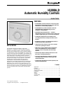
APPLICATION
The H1008A,D Automatic Humidity Controls with
HumidiCalc+™ Software are duct mounted and provide
automatic, low voltage, electronic control of by-pass flow-
through, powered flow-through, steam and drum humidifiers
in central heating systems. The H1008D also controls heat/
energy recovery units and dehumidifiers. The H1008A,D are
designed to automatically adjust the humidity level based on
indoor temperature and humidity, inferred or measured
outdoor temperature and the setting of the frost factor dial.
The frost factor setting is used to maintain a comfortable
humidity level in the home while reducing moisture
condensation on inside windows. The HumidiCalc+™
Software infers the outdoor temperature by monitoring the
equipment cycles and eliminates the need for an outdoor
temperature sensor when used on single-stage gas or oil
furnaces. With the use of the C7089H Outdoor Temperature
Sensor (purchased separately), the H1008A,D also provide
automatic humidity control in heat pump and multi-stage
systems.
FEATURES
• The H1008A,D provides automatic control for by-pass
flow-through, powered flow-through, steam and drum
humidifiers in central heating systems.
• The H1008D also provides automatic control for
dehumidification using heat/energy recovery
ventilators or dehumidifiers.
• Patented Honeywell HumidiCalc+™ Software
eliminates the need for an outdoor sensor on the most
common single-stage, gas or oil forced air equipment.
• Combination temperature and humidity sensor
accurately determines the dewpoint at the control
location.
• Equipment connection can eliminate the need for a
current sensing relay on the blower.
• Simple duct mount requires only a 3/4 in. (19 mm)
circular duct opening for sensors.
• With the use of the C7089H Outdoor Temperature
Sensor, the H1008A,D also provides automatic
humidity control in heat pump and multi-stage
systems.
• Automatically adjusts humidity level based on the
frost factor set by the homeowner.
• Frost factor input allows for variances in furnace
oversizing, window insulation and average daily
climate temperature.
• System status light indicates normal operation, test
mode and fault indication.
Contents
Application........................................................................... 1
Features .............................................................................. 1
Specifications ...................................................................... 2
Ordering Information ........................................................... 2
Installation ........................................................................... 2
Wiring .................................................................................. 4
Settings ............................................................................... 7
System Status ..................................................................... 7
Checkout ............................................................................. 8
68-0207-3

H1008A,D AUTOMATIC HUMIDITY CONTROL
68-0207—32
ORDERING INFORMATION
When purchasing replacement and modernization products from your TRADELINE® wholesaler or distributor, refer to the
TRADELINE® Catalog or price sheets for complete ordering number.
If you have additional questions, need further information, or would like to comment on our products or services, please write or
phone:
1. Your local Home and Building Control Sales Office (check white pages of your phone directory).
2. Home and Building Control Customer Logistics
Honeywell Inc., 1885 Douglas Drive North
Minneapolis, Minnesota 55422-4386 (612) 951-1000
In Canada—Honeywell Limited/Honeywell Limitée, 155 Gordon Baker Road, North York, Ontario M2H 3N7.
International Sales and Service Offices in all principal cities of the world. Manufacturing in Australia, Canada, Finland, France,
Germany, Japan, Mexico, Netherlands, Spain, Taiwan, United Kingdom, U.S.A.
SPECIFICATIONS
IMPORTANT
The specifications given in this publication do not
include normal manufacturing tolerances. Therefore,
this unit may not exactly match the listed
specifications. Also, this product is tested under
closely controlled conditions and some minor
differences in performance can be expected if those
conditions are changed
TRADELINE® Models:
H1008A,D Automatic Humidity Control with HumidiCalc+
Software: Includes template and four mounting screws.
Electrical Ratings:
Power Supply: 18-30 Vac, 60 Hz.
Power Consumption: 2.5 VA at 27 Vac.
Relay Contacts:
Inductive: 2A full load, 10A locked rotor at 24 Vac.
Resistive: 2A
Thermostat/Furnace Load: 11 mA maximum at 24 Vac.
Temperature Ratings:
Operating Range: 45° to 88°F (7° to 31°C).
Storage Range: -40°F to 150°F (-40° to 66°C).
Humidity Ratings:
Always dehumidifies at 58° and above dewpoint.
Allows humidification/dehumidification at 50°F and below
dewpoint.
Does not allow humidification when dewpoint is above 50°F.
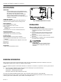
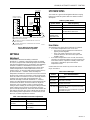
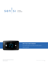
Dimensions:
Refer to Fig. 1.
Accessories:
C7089H Outdoor Temperature Sensor.
Fig. 1. H1008A,D dimensions in in. (mm).
INSTALLATION
When Installing this Product...
1. Read these instructions carefully. Failure to follow them
could damage the product or cause a hazardous
condition.
2. Check the ratings given in the instructions and on the
product to make sure the product is suitable for your
application.
3. Installer must be a trained, experienced service
technician.
4. After installation is complete, check out product operation
as provided in these instructions.
CAUTION
Voltage Hazard.
Power supply can cause electrical shock.
Disconnect power supply before beginning
installation.
1-31/32 (50)
7/16 (11)
4-7/32 (107)
5-1/4 (133)
1-17/32
(39) 4-7/32
(107)
3-1/8
(79)
M12830A

H1008A,D AUTOMATIC HUMIDITY CONTROL
68-0207—3
3
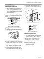
Location and Mounting
H1008A,D Automatic Humidity Control
IMPORTANT
Do not install H1008 on supply air. Temperatures in
excess of 120
°
F cause the control to go into error
mode. If mounting near an elbow area, keep the
control 6 in. (152 mm) upstream from the elbow so
that the humidity and temperature sensor is exposed
to the normal airflow (Fig. 2).
Locate the control at least 12 in. (305 mm) upstream from the
humidifier (or dehumidifion/ventilator supply air) in the return air
duct where it can be exposed to the air stream of the return air.
See Fig. 2.
Fig. 2. Select duct location for control.
Use the following procedure to mount the H1008A,D in the
return air duct:
1. Remove the cover by placing your thumb in the bottom
notch between the cover and the base and pulling out
and up. See Fig. 3.
ALTERNATE LOCATION
RETURN
AIR RETURN
AIR
6 in. (152 mm)
MINIMUM 15 in. (381 mm)
MINIMUM
BEST
LOCATION
RETURN AIR DUCT M12822
M12828
Fig. 3. Remove cover from base.
2. Drill 3/4 in. (19 mm) circular opening for the projection on
the back of the base. See Fig. 4. Place the device on the
duct and mark the mounting holes, or screw in the self-
tapping screws.
NOTE: Be sure the sheet metal surface is flat after
drilling and cutting holes.
3. Mount the base on the duct using the four mounting
screws provided. Tighten the screws firmly so the space
between the base and the duct is seated. See Fig. 4.
M12827
FOR WRAPAROUND
INSERTION STRIP
7/16 IN. (11 MM).
FOR STRAIGHT
INSERTION STRIP
5/16 IN. (8 MM).
BASE
M12829A
3/4 IN. HOLE
4. Run a low voltage wire from the humidifier and
equipment to the control terminals. See Fig. 6-11. Use
either straight in or wraparound wiring connections. See
Fig. 5.
5. Snap the cover onto the base.
Fig. 4. Mount control on return air duct.
Fig. 5. Proper wiring technique.
C7089H Outdoor Temperature Sensor
NOTE: The C7089H Outdoor Temperature Sensor is required
only when using the H1008A control with heat pump,
multi-stage equipment or multi-zone applictions.
Mount the sensor (purchased separately):
—out of direct sunlight on the North side of the house.
—at least three feet from dryer vents or other vents.
—above the expected snow line where ice and debris cannot
cover it.
Use the following procedure for mounting:
1. Place the sensor in the clamp provided.
2. Insert the screw provided through the holes in the clamp
and fasten the sensor in place.

H1008A,D AUTOMATIC HUMIDITY CONTROL
68-0207—34
WIRING
CAUTION
Voltage Hazard.
Power supply can cause electrical shock and injury.
Disconnect power supply before installation or
servicing.
All wiring must comply with applicable local codes,
ordinances and regulations.
IMPORTANT
Use 18- to 22-gauge insulated wire for proper wiring.
Stranded-tinned wire is recommeded.
To wire the Automatic Humidity Control:
IMPORTANT
When installing a steam-powered humidifier, be sure
to cut the factory-installed steam jumper wire for
proper operation.
1. Connect 24 Vac power to the 24 Vac HOT and COM
terminals on the H1008A,D.
2. Connect the humidifier to the two HUM terminals on the
H1008A,D as shown in Fig. 6 through 11.
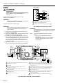
3. In furnace systems with two transformers, connect CG
to the cooling system transformer common and connect
CW to the heating transformer common. Be sure G and
W connect to the R terminals of both transformers. (If
only one transformer is used, leave the jumper on CG
and CW.) See Fig. 6.
4. To Wire the C7089H Outdoor Temperature Sensor, wire
the sensor to the two OUT terminals on the H1008A,D.
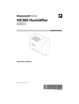
Fig. 7. Wiring for flow-through by-pass humidifiers.
DEHUM
24 VAC
BLACK
WHITE
DEHUM
HUM
HUM
HOT
COM
OUT
OUT
G
CG
CW
W
OFF TEST
24 VAC
SOLENOID
FROST
FACTOR
SETPOINT
DIAL
OPTIONAL
OUTDOOR
AIR SENSOR
1
2
3
4
7
8
6
6
43
AUTOMATIC HUMIDITY CONTROL
M13296
L1
(HOT)
L2
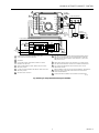
1
POWER SUPPLY. PROVIDE DISCONNECT MEANS AND OVERLOAD
PROTECTION AS REQUIRED.
24V WIRING.
TO PROVIDE HUMIDITY IN FAN MODE, CONNECT G AND CG
TERMINALS TO FAN RELAY.
IN TWO TRANSFORMER SYSTEMS, REMOVE CW/CG FACTORY
INSTALLED JUMPER.
IF USING OUTDOOR TEMPERATURE SENSOR, REMOVE FACTORY
INSTALLED JUMPER.
ISOLATED RELAY CONTACTS.
5
ROOM THERMOSTAT
7
L1
(HOT)
L2 1
R
W
G
FAN
RELAY
HEAT
RELAY
FURNACE
TRANSFORMER
10
9
HEAT ONLY APPLICATION SHOWN. SIMILAR WIRING REQUIRED IN HEAT
AND COOL SYSTEM WITH ONE OR TWO TRANSFORMERS. WHEN HEAT
AND FAN OPERATE SIMULTANEOUSLY WITH ONE RELAY, JUMP W TO G
AND JUMP CG TO CW.
POWER SHOULD BE APPLIED TO THIS CONTROL AT ALL TIMES. DO NOT
USE FAN BOARD HUMIDISTAT CONTACTS OR CURRENT SENSING RELAY.
CUT JUMPER FOR DEHUMIDIFIER APPLICATION. (DO NOT CUT FOR
VENTILATION SYSTEM.)
DEHUM TERMINALS SWITCH LOW VOLTAGE DEHUMIDIFIERS, HEAT/ENERGY
RECOVERY UNITS OR EXTERNAL CONTACTORS THAT SWITCH HIGH
VOLTAGE DEHUMIDIFIERS.
JUMPER AND DEHUM TERMINALS NOT PRESENT ON H1008A MODEL.
8
BLACK
9
10
5
6
FLOW
THROUGH
BYPASS
HUMIDIFIER
11
11
G
CG
CW
W
OUT
OUT
HEATING
TRANSFORMER
POWER SUPPLY. PROVIDE DISCONNECT MEANS AND
OVERLOAD PROTECTION AS REQUIRED.
IN SINGLE TRANSFORMER SYSTEMS, JUMPER CG AND CW.
2
1
M13307
120V
COOLING
TRANSFORMER L1
(HOT)
L2 1
120V L1
(HOT)
L2 1
2
H1008 AUTOMATIC
HUMIDITY CONTROL
HEATING
RELAY
FAN
RELAY
Fig. 6. Wiring for two-transformer system.
IMPORTANT
For proper wiring, use 18- to 22-gauge wire. Stranded-
tinned wire with a maximum length of 300 ft. (91m) is
recommended.
NOTE: Connect the humidistat to the furnace for two
reasons:
•The control can determine the outdoor
temperature.
•The control knows when the furnace blower is
operating, eliminating the need for current
sensing relays.

H1008A,D AUTOMATIC HUMIDITY CONTROL
68-0207—3
5
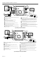
Fig. 8. Wiring for fan-powered flow-through humidifers.
YELLOW
YELLOW
YELLOW
YELLOW
RED
RED
RED
RED
BLACK
BLACK
BLACK
BLUE
BLUE
BLUE
BLUE
WHITE
HOT
COM
OUT
OUT
G
CG
CW
W
OFF TEST
24 VAC
K
HE360 HUMIDIFIER BOARD
CONNECTOR SOLENOID
FROST
FACTOR
SETPOINT
DIAL
OPTIONAL
OUTDOOR
AIR SENSOR
1
1
2
3
4
7
8
POWER SUPPLY. PROVIDE DISCONNECT MEANS AND
OVERLOAD PROTECTION AS REQUIRED.
24V WIRING.
TO PROVIDE HUMIDITY IN FAN MODE, CONNECT G AND CG
TERMINALS TO FAN RELAY.
IN TWO TRANSFORMER SYSTEMS, REMOVE CW/CG FACTORY
INSTALLED JUMPER.
IF USING OUTDOOR TEMPERATURE SENSOR, REMOVE FACTORY
INSTALLED JUMPER.
ISOLATED RELAY CONTACTS.
24V120V
3
2AUTOMATIC HUMIDITY CONTROL
M13295
L1
(HOT)
L2
1
FAN
MOTOR
4
5
10
9
ROOM THERMOSTAT
7
L1
(HOT)
L2 1
R
W
G
FAN
RELAY
HEAT
RELAY
FURNACE
TRANSFORMER
HEAT ONLY APPLICATION SHOWN. SIMILAR WIRING REQUIRED IN HEAT
AND COOL SYSTEM WITH ONE OR TWO TRANSFORMERS. WHEN HEAT
AND FAN OPERATE SIMULTANEOUSLY WITH ONE RELAY, JUMP W TO G
AND JUMP CG TO CW.
POWER SHOULD BE APPLIED TO THIS CONTROL AT ALL TIMES. DO NOT
USE FAN BOARD HUMIDISTAT CONTACTS OR CURRENT SENSING RELAY.
CUT JUMPER FOR DEHUMIDIFIER APPLICATION. (DO NOT CUT FOR
VENTILATION SYSTEM.)
DEHUM TERMINALS SWITCH LOW VOLTAGE DEHUMIDIFIERS, HEAT/ENERGY
RECOVERY UNITS OR EXTERNAL CONTACTORS THAT SWITCH HIGH
VOLTAGE DEHUMIDIFIERS.
JUMPER AND DEHUM TERMINALS NOT PRESENT ON H1008A MODEL.
8
FAN POWERED FLOW THROUGH HUMIDIFIER
DEHUM
DEHUM
HUM
HUM 6
6
9
10
5
6
11
11

H1008A,D AUTOMATIC HUMIDITY CONTROL
68-0207—36
Fig. 9. Wiring for steam humidifiers.
HUMIDISTAT
STEAM HUMIDIFIER
TERMINALS
FAN
WIRING
HOT
COM
OUT
OUT
G
CG
CW
W
OFF TEST
24 VAC
FROST
FACTOR
SETPOINT
DIAL
OPTIONAL
OUTDOOR
AIR SENSOR
1
2
3
4
5
6
9
10
11
4
7
POWER SUPPLY. PROVIDE DISCONNECT MEANS AND OVERLOAD
PROTECTION AS REQUIRED.
24V WIRING.
REFER TO THE STEAM HUMIDIFIER INSTALLATION
INSTRUCTIONS TO WIRE SYSTEM FAN.
CUT JUMPER FOR STEAM HUMIDIFIER CONTROL.
FAN TERMINALS G AND CG NOT USED IN THIS APPLICATION.
EXTERNAL TRANSFORMER NOT PROVIDED.
IF OUTDOOR TEMPERATURE SENSOR IS NOT USED, WIRE HEAT
TERMINALS W AND CW TO FURNACE.
IF USING OUTDOOR TEMPERATURE SENSOR, REMOVE FACTORY
INSTALLED JUMPER.
2
AUTOMATIC HUMIDITY CONTROL
L1
(HOT)
M13298
L2
1
3
6
ISOLATED RELAY CONTACTS.
HEAT ONLY APPLICATION SHOWN. SIMILAR WIRING REQUIRED IN HEAT
AND COOL SYSTEM WITH ONE OR TWO TRANSFORMERS. WHEN HEAT
AND FAN OPERATE SIMULTANEOUSLY WITH ONE RELAY, JUMP W TO G
AND JUMP CG TO CW.
POWER SHOULD BE APPLIED TO THIS CONTROL AT ALL TIMES. DO NOT
USE FAN BOARD HUMIDISTAT CONTACTS OR CURRENT SENSING RELAY.
CUT JUMPER FOR DEHUMIDIFIER APPLICATION. (DO NOT CUT FOR
VENTILATION SYSTEM.)
DEHUM TERMINALS SWITCH LOW VOLTAGE DEHUMIDIFIERS, HEAT/ENERGY
RECOVERY UNITS OR EXTERNAL CONTACTORS THAT SWITCH HIGH
VOLTAGE DEHUMIDIFIERS.
JUMPER AND DEHUM TERMINALS NOT PRESENT ON H1008A MODEL.
24
VAC
TO SYSTEM FAN 8
5
ROOM THERMOSTAT
10
L1
(HOT)
L2 1
R
W
G
HEAT
RELAY
FURNACE
TRANSFORMER
12
13
11
12
13
DEHUM
DEHUM
HUM
HUM 9
9
7
8
14
14
BLACK
DRUM
MOTOR
BLACK
BLACK
WHITE
HOT
COM
OUT
OUT
G
CG
CW
W
OFF TEST
24 VAC
FROST
FACTOR
SETPOINT
DIAL
OPTIONAL
OUTDOOR
AIR SENSOR
1
2
3
4
5
6
4
POWER SUPPLY. PROVIDE DISCONNECT MEANS AND OVERLOAD
PROTECTION AS REQUIRED.
24V WIRING.
TO PROVIDE HUMIDITY IN FAN MODE, CONNECT G AND CG
TERMINALS TO FAN RELAY.
IN TWO TRANSFORMER SYSTEMS, REMOVE CW/CG FACTORY
INSTALLED JUMPER.
IF USING OUTDOOR TEMPERATURE SENSOR, REMOVE FACTORY
INSTALLED JUMPER.
ISOLATED RELAY CONTACTS.
3
2
AUTOMATIC HUMIDITY CONTROL
M13297
L1
(HOT)
L2
1
HEAT ONLY APPLICATION SHOWN. SIMILAR WIRING REQUIRED IN HEAT
AND COOL SYSTEM WITH ONE OR TWO TRANSFORMERS. WHEN HEAT
AND FAN OPERATE SIMULTANEOUSLY WITH ONE RELAY, JUMP W TO G
AND JUMP CG TO CW.
POWER SHOULD BE APPLIED TO THIS CONTROL AT ALL TIMES. DO NOT
USE FAN BOARD HUMIDISTAT CONTACTS OR CURRENT SENSING RELAY.
CUT JUMPER FOR DEHUMIDIFIER APPLICATION. (DO NOT CUT FOR
VENTILATION SYSTEM.)
DEHUM TERMINALS SWITCH LOW VOLTAGE DEHUMIDIFIERS, HEAT/ENERGY
RECOVERY UNITS OR EXTERNAL CONTACTORS THAT SWITCH HIGH
VOLTAGE DEHUMIDIFIERS.
JUMPER AND DEHUM TERMINALS NOT PRESENT ON H1008A MODEL.
5
ROOM THERMOSTAT
7
L1
(HOT)
L2 1
R
W
G
FAN
RELAY
HEAT
RELAY
FURNACE
TRANSFORMER
8
9
10
9
10
DEHUM
DEHUM
HUM
HUM 6
6
DRUM HUMIDIFIER
7
8
11
11
Fig. 10. Wiring for drum-style humidifiers.

H1008A,D AUTOMATIC HUMIDITY CONTROL
68-0207—3
7
Fig. 11. Wiring for R7997, R8184,
RA116 and RA11 Oil Systems.
SETTINGS
Adjustment
The H1008A,D Automatic Humidity Control with
HumidiCalc+™ Software is designed to provide an optimal
50°F (10°C) dewpoint and automatically adjusts the humidity
level to prevent window frost or condensation. The H1008A,D
activates a ventilator or dehumidifier to lower the indoor
humidity level when the house dewpoing rises above 58°F.
Outdoor temperature is inferred (without the need for an
outdoor sensor), or measured (with optional outdoor sensor)
by the HumidiCalc+™ Software. Indoor humidity and
temperature information is measured from sensors located on
the back of the control. The frost factor, set by using the frost
factor dial, allows for variations in furnace oversizing, window
insulation and average daily climate temperature. The
Automatic Humidity Control with HumidiCalc+™ Software
requires an initial adjustment period. To adjust the frost factor,
set the frost factor dial to 10 and use Table 1 to adjust the
frost factor, only one setting at a time, increasing the dial
setting for more humidity, or decreasing the setting if moisture
starts to build up on the inside of your windows. For more
precise humidity adjustments, set the frost factor between the
dial settings. Allow two days for the humidity level to subside
before making further adjustments. Once the frost factor has
been set, no further adjustment is needed.
Table 1. Recommended Frost Factor Adjustment.
SYSTEM STATUS
The control has a green indicator light that flashes at varying
frequencies to indicate system status. See Table 2 for status
descriptions.
Table 2. System Status.
Error Status
To troubleshoot the system when fault status is indicated:
—If an outdoor temperature sensor is not used:
—First check to ensure that the OUT terminals are
properly shorted together.
—Then cycle power to the device. If the control
continues to flash in the error mode, replace the
humidity control.
—If an outdoor temperature sensor is used, disconnect it,
short the OUT terminals together, and cycle power. If the
error status remains, replace the humidity control. If the
error status is eliminated, replace the outdoor
temperature sensor.
Control enters the error mode if any sensor reads out-of-
range. See Table 3.
Table 3. Error Messages.
G
CG
CW
W
OUT
OUT
H1008 AUTOMATIC
HUMIDITY CONTROL
24 VAC
EXTERNAL 24 VAC
TRANSFORMER
CURRENT
SENSING
RELAY
BLOWER
SAIL SWITCH
(OPTIONAL)
POWER SUPPLY. PROVIDE DISCONNECT MEANS AND OVERLOAD
PROTECTION AS REQUIRED.
OPTIONAL SAIL SWITCH IS MONITORING THE OUTPUT AIR
OF THE BLOWER.
CURRENT SENSING RELAY IS MONITORING THE FURNACE
BLOWER MOTOR.
L1
(HOT)
L2
2
3
1
2
M13306A
1
3
Sensor Error Indicated When…
Indoor
temperature Temperature reads below 45°F or greater
than 120°F.
RH sensor RH reads 0 or 100%.
Outdoor
temperature Temperature reads less than -40°F or
greater than 120°F.
OUT terminals At powerup, if sensor is present and later
opens or shorts.
At powerup, if sensor terminals are jumped
and later are open.
System Status Flash Frequency
Error 1/8 second on, 1/8 second off.
Standby 1 second on, 1 second off.
Test 4 seconds on, 1 second off. Steady
on with call for heat or fan.
Call for
humidification/
dehumidification
Steady on.
Off Off.
Humidity Level Recommended Adjustment
Condensation on
windows Decrease the frost factor dial by
one setting.
Insufficient humidity Increase the frost factor dial by
one setting.

H1008A,D AUTOMATIC HUMIDITY CONTROL
68-0207—38
Honeywell Europe S.A.
3 Avenue du Bourget
1140 Brussels
Belgium
Honeywell Asia Pacific Inc.
Room 3213-3225
Sun Hung Kai Centre
No. 30 Harbour Road
Wanchai
Hong Kong
Home and Building Control
Honeywell Limited-Honeywell Limitée
155 Gordon Baker Road
North York, Ontario
M2H 3N7
Honeywell Latin American Region
480 Sawgrass Corporate Parkway
Suite 200
Sunrise FL 33325
68-0207—3 G.H. Rev. 10-99
Home and Building Control
Honeywell Inc.
Honeywell Plaza
P.O. Box 524
Minneapolis MN 55408-0524
Printed in U.S.A. on recycled
paper containing at least 10%
post-consumer paper fibers.
www.honeywell.com
CHECKOUT
NOTE: The furnace blower must be on for the humidifier to
operate (does not apply to steam humidifier
applications).
MPORTANT
When an outdoor sensor is not installed, allow
12 to 24 hours for the humidifier to start operating.
This delay is caused by the method used to
determine outdoor temperature conditions. If the
furnace is off for more than 24 hours or the outdoor
temperature sensor reads greater than 63
°
F, the
control enters an auto off mode where it does not
allow humidification until the furnace cycles or the
outdoor temperature drops below 60
°
F. This is to
prevent the humidifier and air conditioner from
running simultaneously. The control may enter
dehumidification mode if the house dewpoint rises
above 58
°
F.
Outdoor Temperature Sensor Checkout
Check the thermistor sensor by comparing its resistance to
the temperature as measured by an accurate thermometer.
The resistance of the thermistor sensor inceases as its
temperature values drops. Table 4 shows approximate sensor
resistance values at various temperatures.
Test Mode
Use the following procedure to place the control in the test
mode and call for humidification:
1. Turn the frost factor setpoint dial to the Test position.
2. Do one of the following:
a. At the thermostat, with the System switch set to
Heat and the Fan switch set to Auto, move the
temperature setpoint about 10°F (6°C) above the
room temperature to call for heat, or
b. Set the System switch to Off and the Fan switch
to On for continuous fan operation.
3. Verify humidifier and/or dehumidifier/ventilation unit is
activated.
In the test mode, the indicator light remains on continuously
with a call for heat or fan; otherwise, it remains lit for four
seconds and turns off for one second. This flashing sequence
continues until the control is taken out of the test mode. After
thirty minutes, the control automatically resets to the
maximum frost factor setting. If system checkout is not
completed within thirty minutes, the test mode can be
extended by turning the dial back to one of the dial settings
and then returning it to the test mode. After the system has
checked out, return the control to the desired frost factor
setting. See the Adjustment section.
Table 4. Sensor Resistance at Various Temperatures.
Resistance (K ohm) 333 99.2 74.3 56.1 32.9 19.9 12.5 10.0 8.04 6.5
Temperature (°F) -40 -4 5 14 32 50 68 77 86 9.5
Temperature (°C) -40 -20 -15 -10 0 10 20 25 30 3.5
-
 1
1
-
 2
2
-
 3
3
-
 4
4
-
 5
5
-
 6
6
-
 7
7
-
 8
8


Honeywell H1008A,D Automatic Humidity Controls User guide
- Category
- Thermostats
- Type
- User guide
- This manual is also suitable for
Ask a question and I''ll find the answer in the document
Finding information in a document is now easier with AI
Related papers
-
Honeywell HE460A Owner's manual
-
Honeywell HE360 User manual
-
Honeywell HE120B Owner's manual
-
Honeywell HE265A User manual
-
Honeywell HE440A1003 Owner's manual
-
Honeywell HE360B Owner's manual
-
Honeywell HE365B Owner's manual
-
Honeywell HE260A1010 Owner's manual
-
-
Other documents
-
TrolMaster HS-1 Hydro-X Humidistat Station Operating instructions
-
 Honeywell Home HE360 User manual
-
 Sensi 1F96U-42WF Series Touch 2 Smart Thermostat Installation guide
-
 Honeywell Home HE360D1075/U Owner's manual
-
Emerson Humidity Control on Sensi Classic User guide
-
Emerson 1F87U-42WF User guide
-
Honeywell Home HE365 User manual
-
Nest NEST-TSTAT-SS User guide
-
Bryant PREFERREDT A07044 User manual
-
 GOODMAN GMVM971205DN User guide


