Page is loading ...

User Guide
SW HDMI Series
HDMI Switchers
HDMI Switchers
68-2312-01 Rev. B
06 13

Safety Instructions • English
WARNING: This symbol, , when used on the product, is intended to
alert the user of the presence of uninsulated dangerous voltage within
the product’s enclosure that may present a risk of electric shock.
ATTENTION: This symbol, , when used on the product, is intended to alert
the user of important operating and maintenance (servicing) instructions in the
literature provided with the equipment.
For information on safety guidelines, regulatory compliances, EMI/EMF
compatibility, accessibility, and related topics, see the Extron Safety and
Regulatory Compliance Guide, part number 68-290-01, on the Extron
website, www.extron.com.
Instructions de sécurité • Français
AVERTISSEMENT: Ce pictogramme, , lorsqu’il est utilisé sur le
produit, signale à l’utilisateur la présence à l’intérieur du boîtier du
produit d’une tension électrique dangereuse susceptible de provoquer
un choc électrique.
ATTENTION: Ce pictogramme, , lorsqu’il est utilisé sur le produit,
signale à l’utilisateur des instructions d’utilisation ou de maintenance
importantes qui se trouvent dans la documentation fournie avec le
matériel.
Pour en savoir plus sur les règles de sécurité, la conformité à la
réglementation, la compatibilité EMI/EMF, l’accessibilité, et autres sujets
connexes, lisez les informations de sécurité et de conformité Extron, réf. 68-
290-01, sur le site Extron, www.extron.fr.
Sicherheitsanweisungen • Deutsch
WARNUNG: Dieses Symbol auf dem Produkt soll den Benutzer darauf
aufmerksam machen, dass im Inneren des Gehäuses dieses Produktes
gefährliche Spannungen herrschen, die nicht isoliert sind und die einen
elektrischen Schlag verursachen können.
VORSICHT: Dieses Symbol auf dem Produkt soll dem Benutzer
in der im Lieferumfang enthaltenen Dokumentation besonders
wichtige Hinweise zur Bedienung und Wartung (Instandhaltung)
geben.
Weitere Informationen über die Sicherheitsrichtlinien, Produkthandhabung,
EMI/EMF-Kompatibilität, Zugänglichkeit und verwandte Themen finden Sie
in den Extron-Richtlinien für Sicherheit und Handhabung (Artikelnummer 68-
290-01) auf der Extron-Website, www.extron.de.
Instrucciones de seguridad • Español
ADVERTENCIA: Este símbolo, , cuando se utiliza en el producto,
avisa al usuario de la presencia de voltaje peligroso sin aislar dentro
del producto, lo que puede representar un riesgo de descarga
eléctrica.
ATENCIÓN: Este símbolo, , cuando se utiliza en el producto, avisa
al usuario de la presencia de importantes instrucciones de uso
y mantenimiento recogidas en la documentación proporcionada
con el equipo
.
Para obtener información sobre directrices de seguridad, cumplimiento
de normativas, compatibilidad electromagnética, accesibilidad y temas
relacionados, consulte la Guía de cumplimiento de normativas y seguridad de
Extron, referencia 68-290-01, en el sitio Web de Extron, www.extron.es.
Chinese Simplified(简体中文)
警告: 产品上的这个标志意在警告用户该产品机壳内有暴露的危险
电 压 ,有 触 电 危 险 。
注意: 产品上的这个标志意在提示用户设备随附的用户手册中有
重要的操作和维护(维修)说明。
关于我们产品的安全指南、遵循的规范、
EMI/EMF 的兼容性、无障碍
使用的特性等相关内容,敬请访问
Extron 网站 www.extron.cn,参见 Extron
安全规范指南,产品编号
68-290-01。
Chinese Traditional(繁體中文)
警告: 若產品上使用此符號,是為了提醒使用者,產品機殼內存在著
可能會導致觸電之風險的未絕緣危險電壓。
注意 若產品上使用此符號,是為了提醒使用者。
有關安全性指導方針、法規遵守、EMI/EMF 相容性、存取範圍和相關主題的詳細
資訊,請瀏覽 Extron 網站:www.extron.cn,然後參閱《Extron 安全性與法規遵
守手冊》,準則編號 68-290-01。
Japanese
警告: この記号 が製品上に表示されている場合は、筐体内に絶縁されて
いない高電圧が流れ、感電の危険があることを示しています。
注意: この記号 が製品上に表示されている場合は、本機の取扱説明書に
記載されている重要な操作と保守(整備)の指示についてユーザーの
注意を喚起するものです。
安全上のご注意、法規厳守、EMI/EMF適合性、その他の関連項目に
つ い て は 、エ ク スト ロ ン の ウェブ サ イト www.extron.jp より
『Extron Safety and Regulatory Compliance Guide』 (P/N 68-290-01) をご覧ください 。
Korean
경고: 이 기호 , 가 제품에 사용될 경우, 제품의 인클로저 내에 있는
접지되지 않은 위험한 전류로 인해 사용자가 감전될 위험이 있음을
경고합니다.
주의: 이 기호 , 가 제품에 사용될 경우, 장비와 함께 제공된 책자에 나와
있는 주요 운영 및 유지보수(정비) 지침을 경고합니다.
안전 가이드라인, 규제 준수, EMI/EMF 호환성, 접근성, 그리고 관련
항목에 대한 자세한 내용은 Extron 웹 사이트(www.extron.co.kr)의
Extron 안전 및 규제 준수 안내서, 68-290-01 조항을 참조하십시오.
Safety Instructions

FCC Class A Notice
This equipment has been tested and found to comply with the limits for a Class A digital device,
pursuant to part15 of the FCC rules. The ClassA limits provide reasonable protection against harmful
interference when the equipment is operated in a commercial environment. This equipment generates,
uses, and can radiate radio frequency energy and, if not installed and used in accordance with the
instruction manual, may cause harmful interference to radio communications. Operation of this
equipment in a residential area is likely to cause interference; the user must correct the interference at
his own expense.
Copyright
© 2013 Extron Electronics. All rights reserved.
Trademarks
All trademarks mentioned in this guide are the properties of their respective owners.
The following registered trademarks
®
, registered service marks
(SM)
, and trademarks
(TM)
are the property of
RGBSystems, Inc. or Extron Electronics:
Registered Trademarks
(®)
AVTrac, Cable Cubby, CrossPoint, eBUS, EDID Manager, EDID Minder, Extron, Flat Field, GlobalViewer, Hideaway, Inline, IPIntercom, IPLink,
Key Minder, LockIt, MediaLink, PlenumVault, PoleVault, PowerCage, PURE3, Quantum, SoundField, SpeedMount, SpeedSwitch, System
Integrator, TeamWork, TouchLink, V-Lock, VersaTools, VN-Matrix, VoiceLift, WallVault, WindoWall
Registered Service Mark
(SM)
: S3 Service Support Solutions
Trademarks
(
™
)
AAP, AFL (Accu-Rate Frame Lock), ADSP (Advanced Digital Sync Processing), AIS (Advanced Instruction Set), Auto-Image, CDRS (Class D
Ripple Suppression), DDSP (Digital Display Sync Processing), DMI (Dynamic Motion Interpolation), DriverConfigurator, DSPConfigurator, DSVP
(Digital Sync Validation Processing), FastBite, FOXBOX, IP Intercom HelpDesk, MAAP, MicroDigital, ProDSP, QS-FPC (QuickSwitch Front Panel
Controller), Scope-Trigger, SIS, Simple Instruction Set, Skew-Free, SpeedNav, Triple-Action Switching, XTP, XTP Systems, XTRA, ZipCaddy,
ZipClip

Conventions Used in this Guide
Notifications
The following notifications are used in this guide:
CAUTION: A caution indicates a situation that may result in minor injury.
ATTENTION: Attention indicates a situation that may damage or destroy the product or
associated equipment.
NOTE: A note draws attention to important information.
Software Commands
Commands are written in the fonts shown here:
^AR Merge Scene,,Op1 scene 1,1 ^B 51 ^W^C
[01] R 0004 00300 00400 00800 00600 [02] 35 [17] [03]
E X! *X1&* X2)* X2#* X2! CE}
NOTE: For commands and examples of computer or device responses mentioned
in this guide, the character “0” is used for the number zero and “O” is the capital
letter “o.”
Computer responses and directory paths that do not have variables are written in the font
shown here:
Reply from 208.132.180.48: bytes=32 times=2ms TTL=32
C:\Program Files\Extron
Variables are written in slanted form as shown here:
ping xxx.xxx.xxx.xxx —t
SOH R Data STX Command ETB ETX
Selectable items, such as menu names, menu options, buttons, tabs, and field names are
written in the font shown here:
From the File menu, select New.
Click the OK button.
Specifications Availability
Product specifications are available on the Extron website, www.extron.com.

Contents
Introduction ...................................................1
About this Guide ................................................. 1
About the SW HDMI Series Switchers ................ 1
Features ............................................................. 1
Application Diagrams .......................................... 3
Installation ..................................................... 4
Installation Overview ........................................... 4
Rear Panel Features ........................................... 5
Wiring the Power Connector — SW2 and
SW4 HDMI Only (Optional) ................................. 7
Wiring for RS-232 Control .................................. 8
Connecting to the USB Port ............................... 9
Enabling Auto-input Switching .......................... 10
Wiring for Input Selection by Contact
Closure ............................................................ 11
Wiring the Tally Out Port to Indicate the Input
Selection ......................................................... 12
Operation ..................................................... 13
Front Panel Features ......................................... 13
Operations....................................................... 15
Powering on the Switcher ............................. 15
Selecting an Input ......................................... 15
Resetting ...................................................... 16
Using the Optional IR 102 Remote
Control ........................................................ 16
Locking and Unlocking the Front Panel
(Executive Mode) ......................................... 17
EDID Modes ................................................. 17
Remote Communication and Control ....... 21
Using Simple Instruction Set (SIS)
Commands ..................................................... 21
Host-to-switcher Communications ............... 21
Switcher-initiated Messages ......................... 21
Error Responses ........................................... 22
Using the Command and Response Table .... 22
Symbol Definitions ........................................ 23
Command and Response Table for SIS
Commands ................................................ 24
Updating Firmware Using Firmware Loader ...... 27
Downloading and Installing Firmware
Loader ......................................................... 27
Downloading the SW HDMI Firmware ........... 27
Loading the Firmware to the Switcher ........... 28
Reference Information ...............................33
Mounting the SW HDMI .................................... 33
Tabletop Use ................................................ 33
Rack Mounting ............................................. 33
Furniture Mounting—SW2 and SW4 HDMI
Only ............................................................. 33
vSW HDMI Series • Contents

SW HDMI Series • Contents vi

SW HDMI Series • Introduction 1
Introduction
This section gives an overview of the SW HDMI Series switchers. Topics include:
• About this Guide
• About the SW HDMI Series Switchers
• Features
• Application Diagrams
About this Guide
This guide describes the Extron SW HDMI Series switchers and discusses how to install,
configure, and operate them.
In this guide, the term “SW HDMI Series” refers to the SW2, SW4, SW6, and SW8 HDMI
switchers. “Switcher” and “SW HDMI” are used to refer to any single unit.
About the SW HDMI Series Switchers
The SW HDMI Series are two, four, six, and eight input, one output, High-definition
Multimedia Interface (HDMI) switchers. They allow multiple HDMI input signals, including
digital video, 3D signals, and embedded multi-channel digital audio to be switched to
one compatible output display. These switchers support all standard single-link HDMI (up
to 2.25 Gbps) and Digital Video Interface (DVI) 1.0 signal formats. They are compatible
at 60 Hz with all HDTV resolutions up to 1080p and PC resolutions up to 2048x1080,
with 12-bit color, and are fully compliant with High-bandwidth Digital Content Protection
(HDCP).
The SW HDMI switchers can be controlled via the front panel, the RS-232 interface, USB,
contact closure, or the optional IR 102 Remote Control. You can select inputs by pressing
the front panel buttons, pressing buttons on the IR 102, enabling auto-input switching,
attaching a jumper or a contact closure device to the Contact port, or entering Simple
Instruction Set (SIS) commands via RS-232 or USB.
Features
• HDCP authentication — The SW HDMI switchers check the sources and the
display individually for HDCP compliance. HDCP LEDs for each input and the output
indicate successful HDCP authentication.
• Auto-input switching — The SW HDMI Series can be configured to automatically
switch to the highest-numbered active input when the switcher detects a signal.
• Signal detection LEDs — Each input and the output are represented by front panel
LEDs, which light if a signal is present for the input or output and there is activity on
the Transition Minimized Differential Signaling (TMDS) lines.
• Contact closure — The Contact port enables inputs to be selected by contact
closure, with or without a contact closure device.
• Tally output port — Can be used in conjunction with the Contact port to indicate
the selected switcher input.

SW HDMI Series • Introduction 2
• Rack and furniture mounting — The SW HDMI Series can be mounted on a rack
shelf or under a desk or podium with an optional mounting kit.
• Remote configuration and control — The switcher can be configured via an RS-232
or USB connection via SIS commands (see Remote Communication and Control
beginning on page 21).
• EDID Minder — A proprietary EDID (Extended Display Identification Data) management
process from Extron, the EDID Minder manages the EDID between a digital display
device and one or more input sources. By maintaining continuous EDID communication
with all sources, EDID Minder ensures that digital sources power up properly and
maintain their video output, whether or not they are actively connected to the digital
display device.
• EDID modes — Either of the following EDID modes can be selected using SIS
commands:
• Automatic, in which the SW HDMI reads the EDID data when a display is
connected and stores the data in memory (default mode)
• User-assigned, in which you can assign one of 48 factory-provided EDID files
to each input. Four undefined memory slots are also provided, to which you can
save the EDID of connected displays as additional EDID files. The assigned EDID
does not change if a different display device is connected. This mode is useful for
troubleshooting purposes.
Each time power is applied to the output device or when the display is replaced, the
SW HDMI either reads the EDID information from the display or reloads the user-
assigned EDID information. It then writes the information to non-volatile memory on the
inputs. The input devices can read this information as they reboot (see EDID Modes on
page 17 for more information).
• Output compatibility correction — The SW HDMI monitors the EDID on the
connected output device to ensure that it is compatible with the currently selected input
signal. The following corrections are made to the signal as necessary each time an input
is selected:
• Interface format: If the connected output device is DVI and the selected source is
HDMI, the signal is reformatted for DVI. If the output device is an HDMI device, no
reformatting is necessary because HDMI is backwards compatible with DVI.
• Video color bit depth: If the connected output device does not support the color
bit depth of the selected source signal, it is truncated to the next level down that is
supported. For example, 12-bit >10-bit > 8-bit. Bit depth truncation can be forced
via SIS commands to always downgrade to 8-bit depth, disabling deep color.
• IR remote control (optional) — The hand-held IR 102 Remote Control can control
the SW HDMI via infrared signals that it sends to the switcher from a distance of up to
30 feet (9 m).
• Front panel security lockout (executive mode) — To prevent unauthorized access
to the switchers, the front panel controls can be locked via the front panel buttons or
SIS commands (RS-232, USB, and IR control remain available).
• Input cable equalization — Automatic input cable equalization compensates for
signal loss when long cable assemblies are used.
• Power supply —
• SW2 and SW4 HDMI: An energy-efficient, external 12 VDC, 1 A universal power
supply with a 2-pole captive screw connector accepts 100 to 240 VAC.
• SW6 and SW8 HDMI: An 50-60 Hz, internal universal power supply with a
standard IEC connector accepts 100 to 240 VAC.

SW HDMI Series • Introduction 3
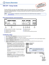
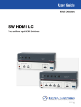
Application Diagrams
The following diagrams show examples of how SW HDMI Series switchers can be
connected.
0.3A MAX
POWER
12V
1
3 4
INPUTS
OUTPUT
Tx Rx
RS-232 AUTO
REMOTE
1 2 3 4 G
CONTACT
1 2 3 4
+v
TALLY OUT
1
31
42
3
1
4
2
3
1
4
2
2
3
100
LINK
ACT
COM
IR
INPUT
RELAY
TX RX
R
IPL 250
®
ON
OFF
DISPLAY
MUTE
SCREEN
UP
SCREEN
DOWN
VCR
DVD
DOC
CAM
LAPTOP
PC
Laptop
DSS Receiver
Blu-ray Player
Extron
SW4 HDMI
Switcher
PC
HDMI
Cables
RS-232
TCP/IP
TouchLink
Control
System
Flat Panel
Display with
Integrated
Speakers
Figure 1. Application Diagram for an SW4 HDMI Switcher
NOTE: HDCP compliant sources require HDCP compliant displays (see the user
manual of the source or display device for information on its HDCP compliance).
SW8 HDMI
50-60Hz
100-240V 0.2A MAX
REMOTE
OUTPUT
INPUTS
1
2
3
4
5
6
7
8
TALLY OUT
CONTACT
RS-232 AUTO
1 2 3 4 +V 5 6 7 8 +V
1
2 3 4 G 5 6 7 8 G
Tx Rx G
1
31
42
3
1
4
2
31
42
2
3
100
LINK
ACT
COM
IR
INPUT
RELAY
TX
RX
R
IPL 250
®
ON
OFF
DISPLAY
MUTE
SCREEN
UP
SCREEN
DOWN
VCR
DVD
DOC
CAM
LAPTOP
PC
Laptop Laptop
Laptop
DSS Receiver
Blu-ray Player
Extron
SW8 HDMI
Switcher
PC
HDMI
Cables
HDMI
Cables
RS-232
TCP/IP
TouchLink
Control
System
Flat Panel
Display with
Integrated
Speakers
Figure 2. Application Diagram for an SW8 HDMI Switcher

SW HDMI Series • Installation 44
Installation
This section describes the installation and setup of the SW HDMI Series switchers. Topics
include:
• Installation Overview
• Rear Panel Features
• Wiring the Power Connector — SW2 and SW4 HDMI Only (Optional)
• Wiring for RS-232 Control
• Connecting to the USB Port
• Enabling Auto-input Switching
• Wiring for Input Selection by Contact Closure
• Wiring the Tally Out Port to Indicate the Input Selection
Installation Overview
To install and set up the SW HDMI switcher:
1. Turn off all equipment and disconnect it from the power source.
2. (Optional) Mount the switcher on a rack shelf or furniture (see Mounting the
SW HDMI on page 33).
3. Connect HDMI input sources to one or more of the SW HDMI input connectors.
4. Connect an HDMI output device to the output connector.
5. Connect control devices. Connect your computer to either of the following
SW HDMI ports to configure and control the switcher via SIS commands:
• RS-232 port — Pins 1, 2, and 3 of the RS-232/Auto connector for serial RS-232
control (see Wiring for RS-232 Control on page 8 for connection procedures)
• Config port — USB mini B connector for USB control (see Connecting to the
USB Port on page 9 for connection procedures)
6. (Optional) Enable auto-input switching. Use a jumper to connect pins 4 and 5 of
the 5-pole captive screw plug that you plugged into the RS-232 connector in step 5
(see Enabling Auto-input Switching on page 10).
7. (Optional) Connect an input device to the SW HDMI Contact port (directly or through
a contact closure device) and, if desired, to the Tally Out port, to enable input
switching by contact closure (see Wiring for Input Selection by Contact Closure
on page 11).
8. Power on the output display.
9. Connect power to the switcher (see Powering On the Switcher on page 15).
10. (Optional) Configure the EDID Minder. By default, the SW HDMI is configured to
automatically store the EDID of the display (automatic mode). If desired, change the
EDID mode to prevent automatic EDID storage and enter the desired EDID manually
(see EDID Modes on page 17).
11. Power on the source devices.

SW HDMI Series • Installation 5
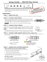
Rear Panel Features
0.4A MAX
POWER
12V
1
Tx Rx
RS-232 AUTO
2
INPUTSSW2 HDMI REMOTE
1234G
CONTACT
1234+v
TALLY OUT
OUTPUT
3
4
1
5
6
2
Figure 3. SW2 HDMI Rear Panel
0.4A MAX
POWER
12V
1
Tx Rx
RS-232 AUTO
234
INPUTSSW4 HDMI REMOTE
1234G
CONTACT
1234
+v
TALLY OUT
OUTPUT
2
3
4
1
5
6
Figure 4. SW4 HDMI Rear Panel
Figure 5. SW6 HDMI Rear Panel
Figure 6. SW8 HDMI Rear Panel
SW8 HDMI
50-60Hz
100-240V 0.2A MAX
REMOTE
OUTPUT
INPUTS
1 2 3 4 5 6 7 8
TALLY OUT
CONTACT
RS-232 AUTO
1234+V 5678+V
1234G5678G
Tx Rx G
1
2
3
4
5
6
SW6 HDMI
50-60Hz
100-240V 0.2A MAX
REMOTE
OUTPUT
INPUTS
1 2 3 4 5 6
TALLY OUT
CONTACT
RS-232 AUTO
1234+V 5+V
1234G5 6G
Tx Rx G
3
4
1
5
6
2
6

SW HDMI Series • Installation 6
a Power connector —
• SW2 and SW4 HDMI: Plug the provided external 12 VDC, 1 A power supply into
this 2-pole, 3.5 mm captive screw connector and into an AC power outlet.
ATTENTION: Do not connect power to the switcher until you have read the
CAUTION and ATTENTION notices on the next page.
• SW6 and SW8 HDMI: Plug the provided AC power cord into this male IEC
connector and into an AC power outlet.
b Input connectors — Connect HDMI video input sources to these female Type A
single-link HDMI connectors. Data rates of up to 6.75 Gbps are supported.
• LockIt brackets: LockIt cable lacing brackets, one for each HDMI input and the
output connector, are provided with the SW HDMI. These brackets secure the
HDMI cables to the rear panel connectors and reduce stress on the connectors,
preventing signal loss due to loose cable connections. For information on
attaching the LockIt brackets, see the LockIt HDMI Cable Lacing Bracket
Installation Guide, available at www.extron.com.
• EDID information: By default, EDID is read from the output device and written
to switcher memory for each input, allowing each source to see the EDID
information for the output device even when the SW HDMI is switching between
sources.
c Output connector — Connect an HDMI display device to this female Type A HDMI
connector.
The EDID information is read from the connected output device via this connector and
is written to memory on each input whenever the output device is connected to this
port and powered on.
NOTE: The EDID information is also read and stored whenever power is recycled
to the connected output device or when the output device is replaced.
d Contact port — Plug one of the provided 5-pole captive screw connectors into this
5-pole, 3.5 mm captive screw port. On the SW6 and SW8 HDMI, plug connectors
into either or both parts of the dual Contact port. You can use this port to switch
inputs by:
• Shorting the ground pin to any of the other four pins in the connector (see
Contact Closure under “Selecting an Input” on page 15).
• Connecting a push-button contact closure device to the port (see Wiring for
Input Selection by Contact Closure on page 11).
e Remote and auto-input switching connector — This 5-pole, 3.5 mm captive
screw connector (labeled “RS-232 Auto”) can be used for RS-232 communication
with the switcher (including firmware updates) and to enable auto-input switching.
• To enable RS-232 control, connect the Tx (transmit), Rx (receive) and G
(ground) pins to the serial port of your computer (see Wiring for RS-232 Control
on page 8).
• To enable auto-input switching, short pins 4 and 5 of this connector together.
In auto-input switch mode, the switcher automatically switches to the highest
numbered active input (see Enabling Auto-input Switching on page 10).

SW HDMI Series • Installation 7
f Tally Out port — (Optional) Plug one of the provided 5-pole captive screw
connectors into this 5-pole captive screw port to indicate which input has been
selected. On the SW6 and SW8 HDMI, plug connectors into either or both parts of
the dual Tally Out port.
Connect an indicator device such as an LED to the attached connector to identify the
currently selected input when the front panel buttons are not visible (see Wiring the
Tally Out Port to Indicate the Input Selection on page 12).
Wiring the Power Connector — SW2 and SW4 HDMI Only (Optional)
A 12 VDC, 1 A power supply is provided with the SW2 and SW4 HDMI. Should it be
necessary to attach a 2-pole captive screw connector to your power supply, follow these
instructions:
CAUTION: Risk of electric shock. The two power cord wires must be kept
separate while the power supply is plugged in. Remove power before wiring.
ATTENTION:
• The power supply must not be permanently fixed to the building structure or
similar structures.
• The power supply must not be located within environmental air handling spaces
or the wall cavity.
• The installation must be in accordance with the applicable provisions of the
National Electrical Code ANSI/NFPA 70, Article 725 and the Canadian Electrical
Code, Part 1, Section 16.
• The power supply must be located in the same vicinity as the Extron AV
processing equipment in an ordinary location, Pollution Degree 2, secured to a
podium, a desk, or an equipment rack within a dedicated closet.
• Always use a power supply specified for the SW HDMI by Extron. Use of an
unauthorized power supply voids all regulatory compliance certification and may
cause damage to the supply and the switcher.
1. Cut the DC output cord to the length needed.
2. Strip the jacket to expose 3/16 inch (5 mm) of the conductors.
ATTENTION:
• Exposing more than 3/16 inch (5 mm) of the copper wires could allow the
stripped wires to touch each other, causing a short circuit. This could result
in the external DC power supply overheating and burning.
• Stripping the wires to expose less than the recommended amount may
cause them to slide out of the connector too easily, even if they are tightly
pinched by the captive screws.
• Do not tin the stripped power supply leads before attaching the captive
screw plug to them. Tinned wires are not as secure in the captive screw
connectors and can be easily pulled out. They may also break after being
bent several times.
3. Slide the leads into the supplied 2-pole captive screw plug and secure them, using a
small screwdriver.
4. To verify the power cord polarity before connecting the plug, connect the power
supply with no load and check the output with a voltmeter.

SW HDMI Series • Installation 8
5. Use the supplied tie wrap to strap the power cord to the extended tail of the
connector.
Captive Screw Connector
Tie Wrap
Heat
Shrink
1/8"
(3 mm)
7/8"
(22 mm)
3/16"
(5 mm) Max.
Figure 7. Wiring the Power Connector
Wiring for RS-232 Control
Use a female 9-pin D to bare wire RS-232 cable or a universal control cable (UC50' or
UC100') to connect your computer or control system to the RS-232 pins of the Remote
connector.
1. Wire the unterminated end of the RS-232 cable to the provided 5-pole captive screw
plug as described below. Connect the transmit, receive, and ground wires of the
cable to the first three pins on the connector, starting at the left:
• Connect the transmit wire to pin 1, which plugs into the Tx (transmit) port.
• Connect the receive wire to pin 2, which plugs into the Rx (receive) port.
• Connect the ground wire to pin 3, which plugs into the G (ground) port.
2. Plug the 5-pole connector into the Remote receptacle on the rear panel of the
switcher.
3. Connect the other end of the cable to the appropriate computer or control system
connector.
Figure 8 shows how to wire this shared connector for RS-232.
RS-232 Auto
Computer or
Control System
RS-232 Port
SW HDMI Series Switcher
Rear Panel
Remote Port
NOTE: If you use cable that has a drain
wire, tie the drain wire to ground at both ends.
TxRx
G
Ground (G)
Transmit (Tx)
Receive (Rx)
Transmit (Tx)
Receive (Rx)
Figure 8. Remote Connector Pin Assignments

SW HDMI Series • Installation 9
Connecting to the USB Port
The mini B USB port is located on the SW HDMI front panel. It can be used to configure
the switcher via SIS commands.
1. Connect a USB A to mini B cable between the USB Config port on the switcher front
panel and the USB port on your computer.
USB Cable
USB A
USB Mini B
USB 1
USB
Ports
Computer
SW HDMI Front Panel
SW4 HDMI
HDMI SWITCHER
1
IR
CONFIG
SIGNAL
INPUTS
INPUTS
OUTPUT
1 2 3 4
HDCP
2 3 4
AUTO
SWITCH
Figure 9. USB Port Connection
2. If this is the first time you have connected an SW HDMI to this USB port on your
computer, the Found New Hardware Wizard opens. On the first screen, specify
whether you want the computer to connect to Windows Update in order to search the
web for the driver that it needs to communicate with the switcher via the USB port.
This is not necessary if the USB driver already exists on your computer.
Figure 10. Found New Hardware Wizard Opening Screen
• Select the Yes, this time only radio button if you want your computer to
connect to Windows Update only this one time.

SW HDMI Series • Installation 10
• Select Yes, now and every time I connect a device if you want the computer
to automatically connect to Windows Update to search the web every time the
switcher is connected to this USB port.
• Select No, not this time if you do not want the computer to connect to
Windows Update to search the web at this time (for example, if the driver is
already on your computer).
3. Click Next. On the next screen, select the Install the software automatically
(Recommended) radio button, then click Next (you do not need to insert a disc).
Figure 11. Selecting the Radio Button to Install the USB Driver
Automatically
Your computer locates the driver needed for it to communicate with the SW HDMI via
the USB port and loads it to the computer hard drive.
4. When the Completed screen appears, click Finish to close the wizard.
NOTE: This wizard appears only the first time you connect the SW HDMI to each
USB port. You do not see the wizard again unless you connect the switcher to
a different USB port on your computer.
5. Configure the switcher as desired using SIS commands (see the Remote
Communication and Control section, beginning on page 21 for information on
available commands).
Enabling Auto-input Switching
You can set up the SW HDMI to automatically select the active, connected input based on
detection of an active video signal (TMDS clock activity). If two or more inputs are active,
the highest-numbered input port with an active signal is selected (for example, input 4 on
an SW4 HDMI switcher). When auto-input switching is in effect, the green Auto Switch
LED on the front panel lights and the front panel input buttons are disabled.
To enable auto-input switching:
1. Cut a small piece of wire to use as a jumper.
2. Insert the ends of the wire into slots 4 and 5 of the provided 5-pole captive screw
plug, connecting pins 4 and 5 together.

SW HDMI Series • Installation 11
3. Use a small screwdriver to tighten the two screws above pin slots 4 and 5 of the plug
so that the jumper wire ends remain securely in place (see figure 12).
4. Insert the plug into the 5-pole Remote captive screw connector on the rear panel.
Figure 12 shows an SW4 HDMI with a jumper connecting pins 4 and 5 to enable
auto-input switching.
FIG_Auto-input switching
0.3A MAX
POWER
12V
1
2
3
4
INPUTS
OUTPUT
Tx Rx
RS-232 AUTO
REMOTE
1 2 3 4 G
CONTACT
1 2 3 4
+v
TALLY OUT
Figure 12. Auto Pins of the Remote Connector with a Jumper Installed
Auto-input switching remains in effect as long as the jumper wire connects the two pins
and the 5-pole captive screw plug is attached to the RS-232/Auto port.
Wiring for Input Selection by Contact Closure
The Contact port provides an alternative method of input selection. Connect a
push-button contact closure device to this port to switch the desired input to the output
as follows:
1. Plug one of the provided 5-pole connectors into the Contact port. On the SW6 and
SW8 HDMI, plug connectors into either or both parts of the dual Contact port.
2. Insert the signal wire of the contact closure device into the slot representing the
desired input number on the SW HDMI Contact port.
Pin 1 = Input 1 contact
Pin 2 = Input 2 contact
Pin 3 = Input 3 contact (SW4, SW6, and SW8 HDMI only)
Pin 4 = Input 4 contact (SW4, SW6, and SW8 HDMI only)
Pin 5 (G) = Contact ground
Pin 6 = Input 5 contact (SW6 and SW8 HDMI only)
Pin 7 = Input 6 contact (SW6 and SW8 HDMI only)
Pin 8 = Input 7 contact (SW8 HDMI only)
Pin 9 = Input 8 contact (SW8 HDMI only)
Pin 10 (G) = Contact ground (SW6 and SW8 HDMI only)
3. Insert the ground wire of the contact device into the G slot of the Contact port (pin 5
or 10).
After wiring the connector, press the button on the contact device to switch the
connected input to the output.

SW HDMI Series • Installation 12
Wiring the Tally Out Port to Indicate the Input Selection
To identify the currently selected input when the front panel buttons are not visible, you
can connect an indicator device such as an LED to an input pin and the +V pin of the Tally
Out port. When the input you are using is selected, the corresponding tally out pin shorts
to ground, which activates the connected indicator.
To connect an indicator to the Tally Out port:
1. Plug one of the provided 5-pole
connectors into the Tally Out port. On the
SW6 and SW8 HDMI, plug connectors
into either or both parts of the dual Tally
Out port.
2. Insert the power wire for the contact
indicator device into the +V slot of the
Tally Out connector (pin 5).
3. Insert the ground wire for the indicator into the slot on the Tally Out port that
represents the input that you want to monitor.
Pin 1 = Input 1 tally ground
Pin 2 = Input 2 tally ground
Pin 3 = Input 3 tally ground (SW4, SW6, and SW8 HDMI only)
Pin 4 = Input 4 tally ground (SW4, SW6, and SW8 HDMI only)
Pin 5 = +5 V
Pin 6 = Input 5 tally ground (SW6 and SW8 HDMI only)
Pin 7 = Input 6 tally ground (SW6 and SW8 HDMI only)
Pin 8 = Input 7 tally ground (SW8 HDMI only)
Pin 9 = Input 8 tally ground (SW8 HDMI only)
Pin 10 = +5 V (SW6 and SW8 HDMI only)
Example: One way to use this port is to connect it to a contact closure device with an
LED. Connect the contact device to the Contact port as well. When you use the contact
device to switch the input you are using, the LED lights.
Tx Rx
RS-232 AUTO
REMOTE
1234G
CONTACT
1234 +v
TALLY OUT
Tally Out Port for
Input Selection
Indication

SW HDMI Series • Operation 13
Operation
This section describes the operation of the SW HDMI Series switchers. Topics include:
• Front Panel Features
• Operations
Front Panel Features
SW2 HDMI
HDMI SWITCHER
1
IR
CONFIG
SIGNAL
INPUTS
INPUTS
OUTPUT
1 2
HDCP
2
AUTO
SWITCH
2
1
3
4
6
5
Figure 13. SW2 HDMI Front Panel
SW4 HDMI
HDMI SWITCHER
1
IR
CONFIG
SIGNAL
INPUTS
INPUTS
OUTPUT
1 2 3 4
HDCP
2 3 4
AUTO
SWITCH
2
1
3
4
6
5
Figure 14. SW4 HDMI Front Panel
Figure 15. SW6 HDMI Front Panel
SW6 HDMI
HDMI SWITCHER
1 2
INPUTS
3
IR
CONFIG
4 5 6
SIGNAL
INPUT
SO
UTPUT
5 61 3 4
HDCP
2
AUTO
SWITCH
1
3
4
2
6
5

SW HDMI Series • Operation 14
Figure 16. SW8 HDMI Front Panel
a Auto Switch LED — This LED lights when auto-input switching is in effect (see
Enabling Auto-input Switching on page 10 for the procedure to set up automatic
input selection).
b IR receiver port — This sensor detects infrared signals from the optional IR 102
remote control at a distance of up to 30 feet and within 40 degrees off the axis (see
Using the Optional IR 102 Remote Control on page 16).
c Input selection buttons and LEDs — Press one of these buttons to select an
input to switch to the output. The LED at the right of each button lights when the
corresponding input is selected. If auto-input switching is in effect, these buttons are
disabled, but the LEDs continue to light to indicate the selected input.
The input buttons are also used to initiate a system reset (see Resetting on page 16)
and to enable and disable front panel lockout (see Locking and Unlocking the
Front Panel (Executive Mode) on page 17).
d Signal status LEDs —
• Inputs: Each input has a corresponding numbered Signal LED, which lights when
a source is connected to the input connector and TMDS clock activity is detected
on it.
NOTE: If the source device connected to the selected input is HDCP
encrypted (requires HDCP authentication), the corresponding signal LED
may not light unless HDCP has been authenticated.
• Output: The Output Signal LED lights when an active sink (output) device is
connected to the HDMI output.
e HDCP status LEDs —
• Inputs: Each input has a corresponding numbered HDCP LED. If the connected
source requires HDCP, the corresponding LED lights when authentication is
successful.
NOTE: HDCP is authenticated on each input regardless of the currently
selected source.
• Output: The Output HDCP LED lights if the currently selected input requires
HDCP and the connected output device has been successfully authenticated.
NOTE: HDCP is re-authenticated on the output whenever a new input is
selected.
f Config port — Connect a USB cable (USB A to mini B) between your computer
and this female USB mini B port to configure and control the switcher via SIS
commands or the Universal Switcher Control Program and to update the firmware
(see Connecting to the USB Port on page 9).
SW8 HDMI
HDMI SWITCHER
1
2
INPUTS
3
IR
CONFIG
4
5
6
7
8
SIGNAL
INPUTS
OUTPUT
56134
HDCP
782
AUTO
SWITCH
1
2
4
3
6
5
/