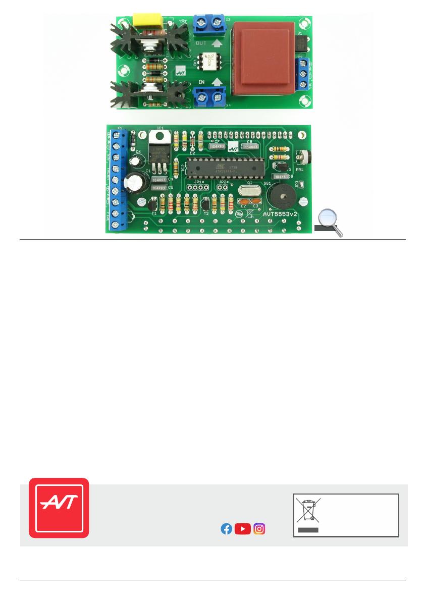
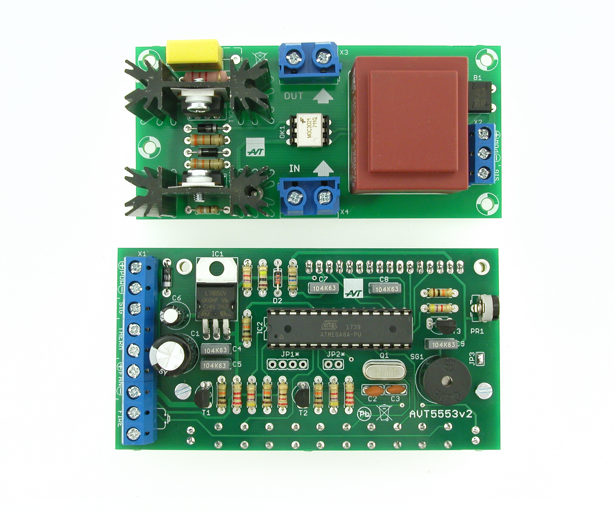
AVT 5553 Controller for Resistance Welder Owner's manual

Type
Owner's manual

AVT 5553 Controller for Resistance Welder aids in joining small metal pieces and attaching battery terminals using a converted microwave oven transformer. It offers precise control over the welding process with adjustable switch-on time, delay, and symmetry of transformer supply, ensuring efficient and accurate welds. The controller features a user-friendly interface with a 2x16 display and buttons for easy operation. It also includes auxiliary circuits for driving a fan and signaling the welding process.

AVT 5553 Controller for Resistance Welder aids in joining small metal pieces and attaching battery terminals using a converted microwave oven transformer. It offers precise control over the welding process with adjustable switch-on time, delay, and symmetry of transformer supply, ensuring efficient and accurate welds. The controller features a user-friendly interface with a 2x16 display and buttons for easy operation. It also includes auxiliary circuits for driving a fan and signaling the welding process.

1
The internet is full of amateur resistance welder
designs for joining small metal parts and attaching
battery terminals. All these designs are based on a
converted transformer from a microwave oven,
which can be bought for a pittance from electronic
scrap or obtained from worn-out equipment.
Transformer from microwave oven have sufficient
power for such applications, approaching 1 kW,
and can be easily and cheaply converted from the
high-voltage version to that required by the
welder.
Features
ideal for welding battery packs.
user interface: 2×16 display and buttons
board sizes:
- controller board: 96×50 mm
- actuating board: 96×45 mm
complete welder requires a transformer from the
microwave oven
Detailed descriptions of the way in which the
transformer should be reworked are best sought on
the web (photos, videos), while at this point we
propose to make a proven and universal controller for
such a welder, ensuring minimisation of inrush current,
adjustment of tripping time and delay, as well as
guaranteeing symmetry of the transformer supply.
Unfortunately, many of the controllers used to date in
such projects are similar to each other and are more or
less faithful modification of the old concept, thus,
unfortunately, reproducing the serious flaws of the
original concept. The proposed controller is directed
to work with a welder, but in practice it can be used to
work with any medium-power transformer. It has an
output stage matched to an inductive load and turns it
on at the maximum of the instantaneous mains
voltage, the complete opposite of more than half of
similar designs. It is worth replacing your existing
controller with this solution.
The controller circuit is supplied with rectified but
unfiltered voltage from the mains transformer, so that
the controller can detect the mains sinusoid passing
through zero. This is done by a circuit made up of
resistors R1 and R2 with protection diode D2, which
provides a pulsing voltage to the microcontroller input.
The voltage is then filtered and stabilised at 5 V using a
three-terminal stabiliser IC1.
Microcontroller is clocked by a clock signal stabilised
Circuit description
Controller for Resistance Welder
The kit is based on a design of the same title published in
Practical Electronics 10/2016. Full version of the original
manual is available to download here:
http://bit.ly/2mpQd8b
AVT 5553
kits
ASSEMBLY DIFFICULTY
PDF
DOWNLOAD
Fig. 1. Schematic diagram
2
by a quartz resonator and works with 5 buttons and a
2×16 character LCD display. Buttons S4 and S5 change
the switch-on time of the welder, S2, S3 adjust the
delay of activation, and S5 switches on the
transformer. A buzzer driver with T3, which signals the
welding process, transistor T2, which switches on the
LED in the optoisolator, and T1, which switches on the
optional fan, operate as auxiliary circuits.
The fan control signal is provided by a 10 kΩ NTC
thermistor inserted between the 4th pin of the X1
connector and GND. A mains transformer is located on
the actuating board, along with a bridge, providing the
supply voltage for the controller. There is also a
thyristor switch based on two thyristors and an
optotriac switched on at any time. Capacitor C10 and
resistor R18 suppress surges that could damage the
thyristors.
MEGA8-P
LCD 2x16
10k
1N4007
1N4148
R
G
27p
27p
100n 100n
100n
100n
7805
4,7k
4,7k
10k
100k
10k
4,7k
2,2k
220
BC327
10k
10k
2,2k
BC337
8MHz
100u1000u
BC337
4,7k
10k
100n
5V
GND
GND
GND
GND
GND
GND
+5V
+5V
+5V
+5V
+5V
+5V
+5V
56
MOC3021
2,2k
330
390
100n
1A
TYN616
TYN616
1N4007
1N4007
330
2VA/6V
GND
PB5(SCK) 19
PB7(XTAL2/TOSC2)
10
PB6(XTAL1/TOSC1)
9
GND
8
VCC
7
GND
22
AREF
21
AVCC
20
PB4(MISO) 18
PB3(MOSI/OC2) 17
PB2(SS/OC1B) 16
PB1(OC1A) 15
PB0(ICP) 14
PD7(AIN1) 13
PD6(AIN0) 12
PD5(T1) 11
PD4(XCK/T0) 6
PD3(INT1) 5
PD2(INT0) 4
PD1(TXD) 3
PD0(RXD) 2
PC5(ADC5/SCL) 28
PC4(ADC4/SDA) 27
PC3(ADC3) 26
PC2(ADC2) 25
PC1(ADC1) 24
PC0(ADC0) 23
PC6(/RESET)
1
IC2
GND
1
VCC
2
CONTR
3
RS
4
R/W
5
E
6
D0
7
D1
8
D2
9
D3
10
D4
11
D5
12
D6
13
D7
14
A
15
K
16
DIS1
PR1
3 1
24
S1
3 1
24
S2
3 1
24
S3
3 1
24
S4
3 1
24
S5
D1
D2
LED1
LED2
C2
C3
C4 C5
C8
C7
GND
IN OUT
IC1
R1
R4
R3
R2
R8
R9
R10
R6
R5
R11
R7
T2
T1
Q1
C6
C1
T3
R13
R14
C9
- +
SG1
R12
X1-1
X1-2
X1-3
X1-4
X1-5
X1-6
X1-7
X1-8
X1-9
FIREFANTHERMPOW
POW
SIG
SIG
1
24
6
OK1
R18
R17
R15
C10
B1
TY2
TY1
D3
D4
R16
X2-1
X2-2
X2-3
X31
X32
X41
IN
OUT
X42
21
JP3
TS1
FAN
FAN
RS
RS
TERM
TERM
TERM
ZERO
ZERO
BUZZ
BUZZ
OUT
OUT
D4
D4
D5
D5
D6
D6
D7
D7
E
E
S1
S1
S2
S2
S3
S3
S4
S4
S5
S5
S1.1
S1.1
LCD DISPLAY 16x2
+
+
PRI
SEC
3
Mounting diagram is shown in Figure 2. Mounting is
typical and needs no special discussion. Controller
board contains components on both sides of the
laminate. One side houses the LCD display, control
buttons and LEDs, the other the remaining
components. The display was soldered to the board
using a goldpin connector, and details are shown in
the photographs. Starting up the controller is basically
limited to switching on the power and setting the
contrast with potentiometer PR1. When you press the
release button, the red LED should light up and a
sound should be heard (with jumper JP3 shorted). If
the controller is supplied with DC voltage for testing, it
will not be possible to determine when zero appears in
the voltage supply, thereby determining the precise
moment of release. The controller in such a situation
will refuse to operate and will display an appropriate
error message. However, by attaching a jumper to pins
1-2 in JP1, this message can be bypassed and the
controller can be forced to work 'blindly'. Adjustment
of the tripping time is possible from 20 ms onwards in
20 ms steps, in order to maintain an even number of
grid periods fed into the transformer. Delay can be
adjusted from zero in 10 ms increments. Times from
the top down are basically unlimited. Fan tripping
threshold has been pre-set at around 40ºC, but by
pressing the two buttons responsible for setting the
time and switching on the power at the same time, this
can be changed. It is then necessary to place the
thermistor in an environment with a threshold
temperature and using the delay buttons, change the
position of the switch-on threshold in a wide range.
Start-up of the actuating board is best done without
the welder transformer. Instead, an ordinary 40-100 W
incandescent bulb connected in series with a thyristor
circuit can be used. When all is OK, it will light up when
"FIRE” is pressed for the desired time. Using the
controller for other applications is possible, but
requires thought and careful selection of thyristors and
the R2/C2 suppression circuit. The same applies to
higher power welders, as some people multiply the
power of the welder by combining two or even four
transformers together. Such combinations have not
been tested here.
Fig. 2. Arrangement of components on the PCB. Fig. 2. Arrangement of components on the PCB.
123456789
1 2 3
12
1 2
Mounting and start-up
4
List of components
Resistors:
R1, R4, R9, R13:......................4,7 kΩ
R2: ..............................................100 kΩ
R3, R5, R8, R11, R14:............10
R6: ..............................................220 Ω
R7, R10:.....................................2,2
R12:............................................56 Ω
R15:............................................390 Ω / 0,5 W
R16, R17: ..................................330 Ω / 1 W
R18:............................................2,2 kΩ / 2 W
PR11: ........................................mounting potentiometer 10 kΩ
Capacitors:
C1: ..............................................1000 uF
C2, C3:....................................... 27 pF
C4, C5, C7-C9: ........................100 nF
C6: ..............................................100 uF
C10:............................................100 nF / 250 VAC
Semiconductors:
IC1: .............................................7805
IC2: .............................................ATmega8
T1, T3:........................................BC337
T2:.........................BC327
D1, D3, D4: ........1N4007
D2: ........................1N4148
LED1:....................red LED, 3 mm
LED2:....................green LED, 3 mm
OK1: .....................MOC3021
B1:.........................bridge 0,5 A / 50 V
TY1, TY2:.............TYN616 + heat sink
DIS1: ....................LCD 2×16
Other
S1-S5: ..................button 13.5 mm
SG1:......................buzzer with 5 V generator
TS1: ......................transformer 2-2,5VA/6VAC
Q1:........................8 MHz
X1, X2: .................DG301-5.0/3
X3, X4: .................DG360-7.5/2
Other mounting components
Optional components:
Thermistor NTC 10 kΩ
Fan 5 VDC
ZOOM
AVT SPV reserves the right to make changes without prior notice.Installation and connection of the appliance not in accordance with the instructions, unauthorised modification of
components and any structural alterations may cause damage to the appliance and endanger persons using it. In such a case, the manufacturer and its authorised representatives shall
not be liable for any damage arising directly or indirectly from the use or malfunction of the product.
The self-assembly kits are intended for educational and demonstration purposes only. They are not intended for use in commercial applications. If they are used in such applications, the
purchaser assumes all responsibility for ensuring compliance with all regulations
This symbol means do not dispose of your
product with your other household waste.
Instead, you should protect human health
and the environment by handing over your
waste equipment to a designated collection
point for the recycling of waste electrical
and electronic equipment.
Leszczynowa 11 Street,
03-197 Warsaw, Poland
https://sklep.avt.pl/
AVT SPV Sp. z o.o.
kits
  • Page 1 1
  • Page 2 2
  • Page 3 3
  • Page 4 4

AVT 5553 Controller for Resistance Welder Owner's manual

Type
Owner's manual

AVT 5553 Controller for Resistance Welder aids in joining small metal pieces and attaching battery terminals using a converted microwave oven transformer. It offers precise control over the welding process with adjustable switch-on time, delay, and symmetry of transformer supply, ensuring efficient and accurate welds. The controller features a user-friendly interface with a 2x16 display and buttons for easy operation. It also includes auxiliary circuits for driving a fan and signaling the welding process.

Ask a question and I''ll find the answer in the document

Finding information in a document is now easier with AI