Page is loading ...

COD. 1247003-GB / 1.1
ACTIVA-GO
1
This unit allows to enhance the receiver area and receiving points when a wider range is necessary (for MOTION and DCS
receivers).
1. DESCRIPTION OF THE MOTHER BOARD
TECHNICAL CHARACTERISTICS
Power supply
12V dc (9Vdc-21Vdc)
Frequency
868,35MHz
Consumption standby / operating
14mA/36mA
Operating temperature
-20ºC to +85ºC
Watertightness
IP54 (with glands IP65)
Dimensions
82x190x40mm
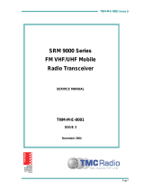
2. INSTALLATION AND CONNECTIONS
Attach the rear part of the chassis to the wall using the plugs and screws supplied. Pass the cables through the bottom of
the receiver. Connect the power cables to the terminals marked in the mother board, as indicated. Mount the receiver
front and pass the cables and the antenna through it.
Terminals
+ 12V dc supply
- 12V dc supply
S / D0 Decoded signal output (DCS)
D / D1 Decoded signal output (BUS-L)

COD. 1247003-GB / 1.1
ACTIVA-GO
2
3. COMPATIBILITY WITH PROGRAMMING MODES OF MOTION AND DCS RANGES
This unit allows to integrate MOTION line transmitters on an existing DCS equipped facility. The following tables show the
compatibilities between the different programming modes depending on the different receivers and transmitters.
RECEIVERS
TRANSMITTERS
DCS
MOTION
DCS
Manual programming
SI
SI
Programming via radio
SI
SI
Programming via programmer
NO
SI
Programming via PIN
NO
SI
Note: To operate with an installer code: Bridge the PROG pins, the LED will turn ON. Activate the transmitter up to the
point that the LED goes OFF and indicates that the installer code is inserted correctly.
4. GROUPS
Interfaces can be configured with a group (from 0 to 7) so that there is no interference when working near each other.
Useful for working with the system FREE.

COD. 1247003-GB / 1.1
ACTIVA-GO
3
4.1. GROUP CONFIGURATION
To configure the group, the PROG pins should be short-circuited and a tag activation should be make. The interface will
be configured with the first tag activated in hands free mode. If you work with transmitters, these will always be
configured with group 0.
Operations
On powering the interface, the led TX will flash the same number of times as the group number with which it is
configured.
5. USE OF THE INTERFACE
These interfaces are designed for use as remote controls for automatic doors. Their use is not guaranteed for directly
activating any other equipment different to that specified.
The manufacturer reserves the right to modify equipment specifications without prior notice.
6. IMPORTANT APPENDIX
In compliance with the European low voltage directive, please be advised of the following requirements:
· This equipment must be installed in a vertical position and firmly fitted to the building structure.
· This equipment can only be handled by a specialist fitter, by his maintenance staff or by a suitably trained operator.
· The instructions for using this equipment must remain in the possession of the user.
· This equipment is designed for use as a remote control for garage doors and access control. Its use is not guaranteed for
directly activating any other equipment different to that specified.
· The manufacturer reserves the right to modify equipment specifications without prior notice.
JCM TECHNOLOGIES, S.A., declares that this ACTIVA-GO is in compliance with the essential requirements and other
relevant provisions of Directive 1999/5/EC.
CE DECLARATION OF CONFORMITY
See web www.jcm-tech.com
/