Page is loading ...

DRAFT - 11 December 2014
MTL4850 and MTL4854
HART® Connection Systems
March 2015
INM 4850_54 Rev4
Instruction Manual
MTL HART
®
Interfacing Solutions

DRAFT - 11 December 2014DRAFT - 11 December 2014
ii
DRAFT - 11 December 2014
INM MTL4850_54 Rev4
DECLARATION OF CONFORMITY
We declare under our sole responsibility that the MTL4850 and MTL4854 and associated products listed below, to which
this declaration relates, conform to the requirements of the Directives below by compliance with the standards listed:
1. Council Directive 2004/108/EC (EMC Directive) relating to Electro-Magnetic Compatibility.
EN 61326-1:2006 Class A equipment. Table 2 - Industrial Locations
2. Council Directive 94/9/EC (ATEX Directive) relating to equipment and protective systems intended for use in
potentially explosive atmospheres. EN 60079-0:2012, IEC 60079-15:2010
Where products were initially assessed for compliance with the Essential Health and Safety Requirements of the Directive
using earlier harmonised standards, a subsequent review has determined that “technical knowledge” is unaffected by the
current harmonised standards listed above.
Product Description EMC
1
LV D
2
ATEX
3
Cat1/Cat2
ATEX Cert No.
Cat3
ATEX Cert No.
MTL4850 HART
multiplexer
Ye s N/R Ye s None MTL08ATEX4850X
MTL4854 HART
multiplexer
Ye s N/R Ye s None MTL08ATEX4850X
HMx64 HART
multiplexer
carrier
Ye s N/R Ye s None MTL08ATEX4850X
HTP-SC16x HART
multiplexer
carrier
Ye s N/R Ye s None MTL08ATEX4850X
HCU16x HART
connection
unit
Ye s N/R Ye s None MTL08ATEX4850X
Notes relating to CE Marking:
1. Entries in this column may be:
Yes Product conforms to the EMC Directive
N/R Product is not required to conform to the EMC Directive
2. Entries in this column may be:
Yes Product conforms to the LVD Directive
N/R Product is not required to conform to the LVD Directive
3. Entries in this column may be:
Yes Product conforms to the ATEX Directive
N/R Product is not required to conform to the ATEX Directive

DRAFT - 11 December 2014DRAFT - 11 December 2014
INM MTL4850_54 Rev4
iii
DRAFT - 11 December 2014
GENERAL SAFETY INFORMATION
The following methods are used in this manual to alert the user to important information:-
WARNING!
Warnings are provided to ensure operator safety and MUST be followed.
CAUTION
Cautions are provided to prevent damage to the instrument
NOTE
These are used to give general information to ensure correct operation
Safety instructions for installation and operating personnel
The operating instructions provided here contain essential safety instructions for installation personnel and those engaged in
the operation, maintenance and servicing of the equipment.
WARNING!
Failure to comply with these instructions can endanger the lives or health of
personnel and risk damage to the plant and the environment.
WARNING!
The responsibility for planning, installation, commissioning, operation and
maintenance, particularly with respect to applications in explosion-hazard areas,
lies with the plant operator
Before commencing installation or commissioning:
• Read and understand the contents of this manual and the product datasheet
• Ensure installation and operating personnel have received adequate training for this task
• Ensure that any operating instructions are fully understood by the personnel responsible.
• Observe national and local installation and mounting regulations (e.g. IEC 60079-14).
WARNING!
If these assemblies have been used previously in general electrical
installations, they MAY NOT be used in explosion-hazard area applications.
During operation:
• Make the relevant instructions available at all times to the operating personnel.
• Observe safety instructions.
• Observe national safety and accident prevention regulations.
• Operate the equipment within its published specification.
• Servicing, maintenance work or repairs not described in this manual must not be performed without prior agreement
with the manufacturer.
• Any damage to this equipment may render its explosion protection null and void.
• No changes to any of the components that might impair their explosion protection are permitted.
If any information provided here is not clear, contact MTL or one of its representatives.
NOTE
Incorrect installation and operation of this equipment can result in invalidation of the guarantee.

DRAFT - 11 December 2014DRAFT - 11 December 2014
iv
DRAFT - 11 December 2014
INM MTL4850_54 Rev4
THIS PAGE IS LEFT INTENTIONALLY BLANK

DRAFT - 11 December 2014DRAFT - 11 December 2014
INM MTL4850_54 Rev4
v
DRAFT - 11 December 2014
CONTENTS
1 INTRODUCTION ....................................................................1
2 DESCRIPTION ......................................................................1
2.1 General purpose or IS? .....................................................................3
2.2 Generic or custom? ........................................................................3
2.3 Connection methods .......................................................................3
3 SAFETY INFORMATION .............................................................5
3.1 Precautions - General .......................................................................5
4 INSTALLATION .....................................................................5
4.1 HTP-SC32 HART connection unit .............................................................5
4.2 HMP-HM64 HART interface ..................................................................7
4.3 HCU16 HART connection unit ...............................................................10
4.4 HCU16AO HART connection unit ............................................................12
4.5 MTL customised backplanes ................................................................14
4.6 CPH-SC16(R) and CPH-SC32(R) backplanes ....................................................14
4.7 Backplane mounting ......................................................................16
4.8 Backplanes – identification and tagging ......................................................17
4.9 Backplane earth rails ......................................................................17
4.10 Backplanes – connections ..................................................................18
4.11 Cabling recommendations .................................................................20
4.12 RS485 connection .........................................................................20
5 MODULES ........................................................................22
5.1 MTL4850 – installation .....................................................................22
5.2 Isolator modules (if used) ..................................................................22
5.3 MTL4850 module .........................................................................22
6 FAULT FINDING AND ROUTINE MAINTENANCE ........................................23
6.1 Maintenance precautions for MTL4500 modules ...............................................23
6.2 Fault finding on custom backplanes .........................................................23
6.3 Routine maintenance ......................................................................24
7 SOFTWARE CONNECTIVITY .........................................................24
7.1 Introduction .............................................................................24
7.2 Communication modes ....................................................................24
7.3 Software setup ...........................................................................25
8 APPLICATIONS INVOLVING ZONE 2 HAZARDOUS AREAS ................................26
8.1 General .................................................................................26
8.2 Installation ..............................................................................26
8.3 Inspection and maintenance ................................................................26
8.4 Repair ..................................................................................27
8.5 Marking .................................................................................27
9 APPENDIX A - TYPICAL COMPATIBLE SYSTEMS .........................................27
10 APPENDIX B - ALARM EVENT LOG ...................................................28

DRAFT - 11 December 2014DRAFT - 11 December 2014
vi
DRAFT - 11 December 2014
INM MTL4850_54 Rev4
THIS PAGE IS LEFT INTENTIONALLY BLANK

DRAFT - 11 December 2014DRAFT - 11 December 2014
INM MTL4850_54 Rev4
1
DRAFT - 11 December 2014
1 INTRODUCTION
This instruction manual describes the procedures for installing, connecting, checking and
maintaining the MTL4850 HART
®
maintenance system, which is a simple interface between
smart devices in the field and HART instrument management software running on a PC.
The following sections are outlined here.
Section 2 describes the system and the solutions available
Section 3 covers some safety aspects.
Section 4 deals with the installation of carriers and mounting backplanes
Section 5 describes installing and configuring the modules
Section 6 provides information on fault finding, and maintenance
Section 7 introduces software for the MTL4850 System.
See the MTL web site (www.mtl-inst.com) for the full specifications of the MTL4850 system
components and accessories, and the MTL4500 Series isolators mentioned in this manual.
2 DESCRIPTION
The MTL4850 HART Maintenance System enables a user to calibrate, configure and maintain
an entire network of 'smart' field devices from a single workstation.
The key element that makes this possible is the MTL4850 or MTL4854 modules, which provide
the multiplexing for the individual field devices, making each one addressable and identifiable
from the workstation.
The other important element is the terminal circuit board that simplifies the interconnection
of the field devices to the multiplexer module. A range of terminal boards and backplanes has
been designed to suit most general applications but custom versions can also be designed to
suit individual OEMs and their applications.
HART
®
is a registered trademark of the HART Communication Foundation
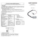
MTL4850 and MTL4854 HART multiplexer
Figure 1.1 - MTL4850 modules mounted on HMP-HM64 carrier

DRAFT - 11 December 2014DRAFT - 11 December 2014
2
DRAFT - 11 December 2014
INM MTL4850_54 Rev4
The multiplexer module, MTL4850 or MTL4854, uses a plug-in style with fixing screws to
provide a simple and secure installation method onto the backplane.
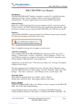
Up to 32 field devices can be accommodated by each HART multiplexer module, which is
then connected via an RS485 to USB (or Ethernet) converter, to the PC running the HART
maintenance software. Depending upon the management software, up to 63 of the multiplexer
modules can be connected to it, making a potential count of 2016 smart field devices on one
serial link. See Figure 2.1 for a diagrammatic impression of this structure.
For intrinsically safe applications, consideration must be given to the safety parameters for
each field loop. For further information, please refer to MTL or your local representative.
The MTL4850 has a single HART modem to service the channels connected to the module
whilst the MTL4854 has four HART modems. The latter enables simultaneous communication
with multiple field devices through a single multiplexer, providing obvious benefits for
applications where speed of data access is important.
NOTE
For any application of the multiplexers where connection is made to signals which are part
of a safety instrumented system then the MTL4850 must be used. Refer also to the safety
manual for the MTL4850 available from the MTL website.
HART
®
is a registered trademark of the HART Communication Foundation
Safe area
Hazardous area
Figure 2.1 - System Overview (typical installation)
Up to 63 MTL4850/54 modules

DRAFT - 11 December 2014DRAFT - 11 December 2014
INM MTL4850_54 Rev4
3
DRAFT - 11 December 2014
2.1 General purpose or IS?
The MTL HART Management System can be used to control and maintain field devices that
are located in a safe area or a hazardous areas.
For safe areas, HART Connection Units provide the necessary terminals to connect up to
32 field devices. These may be basic connection units, linked to a HART interface board, or
they may be integrated units with an MTL4850 or MTL4854 multiplexer onboard. Section 2.3
explains this in more detail.
Hazardous-area field devices can be handled using IS isolating interfaces conveniently
mounted on a backplane with facilities for onward connection to the host. Here also there is a
choice of a backplane with an onboard HART multiplexer (CPH models), or legacy backplanes
that can be linked to a HART interface board that carries the multipexer(s).
Having the isolators mounted on a backplane dramatically reduces the amount of hand wiring
required and therefore reduces the number of potential wiring errors. The hazardous-area
wiring terminates on the isolating modules, not the backplane, consequently the backplanes
do not need IS certification.
2.2 Generic or custom?
A range of generic connection units is available for both input and output field-device wiring.
These are not designed for any particular DCS type and may be used universally.
The alternative is to choose a connection unit or backplane that integrates with the type of
DCS being used on the plant. The key advantage of this method is the use of a DCS’s specific
connector type, which simplifies the wiring of the connection units into the system. Various
solutions are available to suit individual DCS types and a listing of the currently available
connection units and backplanes is given in Appendix A.
2.3 Connection methods
There are currently three methods for linking the HART signals to the MTL4850 or MTL4854:
a) using an integrated connection unit – HTP-SC32 - see Figure 2.2
b) via a connection unit to a HART interface (HMP-HM64) - see Figure 2.3
c) using an IS isolator backplane with a HART interface - see Figure 2.4
NOTE
the MTL4850/54 may also be used to update existing HART installations, but these
methods are not discussed here. Consult MTL for information if this is of interest.
The self-contained (non-IS) connection unit - see Figure 2.2 - is a 32 channel connection
unit with screw terminals for the field devices and the main system, and an integrated
multiplexers. Up to 63 of these connection units can be daisy-chained on an RS485 link to a
PC runnning HART maintenance software. Apart from an RS485 to USB (or Ethernet) protocol
converter, no other external hardware is required.
See Section 4.1 for details.
MTL4850/54
Figure 2.2
self-contained
HTP–SC32

DRAFT - 11 December 2014DRAFT - 11 December 2014
4
DRAFT - 11 December 2014
INM MTL4850_54 Rev4
The second alternative - see Figure 2.3 - is to use one of MTL's HART connection units:
•
HCU16 16-channel analogue input/output
•
HCU16AO 16-channel analogue output with HART filters
and link to an HMP-HM64 HART interface, which can accommodate any combination of four of
these connection units.
The HMP-HM64 is a compact interface between the connection units and the maintenance
system. Up to 32 of these can be daisy-chained on an RS485 link to a PC runnning HART
maintenance software, making a total coverage of 2016 channels. See Sections 4.2 to 4.5 for
details.
The final method considered here consists of two backplane options.
•
16-channel backplane CPH-SC16 and CPH-SC16R
•
32-channel backplane CPH-SC32 and CPH-SC32R
Both backplanes accommodate 16 MTL4500 Series IS isolator modules and an MTL4850 or
MTL4854 multiplexer module.
The CPH-SC16 backplane is designed for MTL4541 single channel isolators and has 16 field terminals,
while the CPH-SC32 has 32 field terminals for MTL4544/4544A dual channel isolator modules.
RS485 ports on the backplanes enable them to be connected to the HART maintenance software PC.
In addition, both backplanes have a facility to accept dual (redundant) power supplies for
maximum system availability.
MTL4850/54
Figure 2.4
HART CPH-SCxx
backplane
Figure 2.3
HART
connection unit

DRAFT - 11 December 2014DRAFT - 11 December 2014
INM MTL4850_54 Rev4
5
DRAFT - 11 December 2014
3 SAFETY INFORMATION
Before beginning the installation of any of this equipment it is IMPORTANT that the
information in this section is read and understood.
3.1 Precautions - General
WARNING!
Units MUST NOT be installed in a hazardous area unless certified and marked for this
purpose or unless protected by a locally accepted explosion-proof technique.
• Make sure all installation work is carried out in accordance with local standards, codes
of practice, and site regulations.
• Check that the hazardous-area equipment complies with the descriptive system
document.
• If in doubt, refer to the certificate/catalogue for clarification of any aspects of intrinsic
safety or contact MTL, or your local representative, for assistance.
• Check that the interface unit(s) functions(s) are correct for the application.
4 INSTALLATION
This section details the methods used to implement the connection options outlined in
Section 2.3.
4.1 HTP-SC32 HART connection unit
As a simple solution for handling the HART maintenance signals passing to and from the field
devices the HTP-SC32 will often be the primary method of choice. It is intended for analogue
input signals but may also be used for analogue outputs if the host system is compatible with
HART communications.
Able to handle up to 32 channels through its screw-clamp field and system terminals, it is
a convenient way to integrate HART maintenance facilities. The HTP-SC32 provides a self-
contained solution because the MTL4850/54 HART multiplexer is already on-board and
requires only DC power and a simple RS485 link to the host management PC to get started.
Two terminals are provided for each channel enabling connections to be made to 2-wire
transmitters, 4/20mA current loops or voltage inputs. Each channel is isolated so it may be
connected to any suitable point in the analogue loop, and input and output types may be mixed.
HART signals have to be terminated into an impedance of >240W, so provision is made on the
circuit board to fit parallel resistors - normally 250W - or a series resistor if the input impedance
at the point of connection is <240W. Various models are available to suit these termination
options. Table 4.1 identifies the models and their specific differences and Figure 4.2 shows how
these models are used.
Figure 4.1
HTP–SC32
backplane

DRAFT - 11 December 2014DRAFT - 11 December 2014
6
DRAFT - 11 December 2014
INM MTL4850_54 Rev4
Model Description
HTP-SC32
no parallel resistor, zero ohm link fitted in series
(used for current inputs with 250
W input impedance or HART compatible
outputs)
HTP-SC32-P250
250W parallel resistor, zero ohm link fitted in series
(used for 1–5V system inputs)
HTP-SC32-S150
no parallel resistor, 150W resistor fitted in series
(used for current inputs with100
W input conditioning)
HTP-SC32-S200
no parallel resistor, 200W resistor fitted in series
(used for current inputs with 50 or 63.5
W input conditioning)
HTP-SC32-S240
no parallel resistor, 240W resistor fitted in series
(used for outputs with isolator connected to field terminals. Use HMU16AO
for direct connection to field device)
4.1.1 Application examples
Tab le 4.1
HTP-SC32
model
options
A
B
DCS input
+
DCS input
–
+24V or Tx+ from DCS
Tx
2 wire
transmitter
input
A
B
Tx+
Ch+
HART
Tx+
Ch+
Link
250Ω
Figure 4.2a
HTP-SC32
for 2-wire Tx
A
B
DCS input
+
DCS input
–
+24V or Tx+ from DCS
Tx
2 wire
transmitter
input
A
B
Tx+
Ch+
HART
Tx+
Ch+
200Ω
50Ω
Figure 4.2b
HTP-SC32-S200
for 2-wire Tx
DCS input
+
DCS input
–
Tx
4 wire
transmitter
input
A
B
HART
Ch+
250Ω
Link
Ch–
A
B
Ch+
Ch–
Power
Figure 4.2c
HTP-SC32
for 4-wire Tx
DCS input +
DCS input –
T
x
4 wire
transmitter
input
HART
Ch+
250Ω
Link
Ch–
A
B
Ch+
Ch–
Power
1 – 5V input
A
B
Figure 4.2d
HTP-SC32-P250
for 4-wire Tx
DCS input
+
DCS input
–
Smart Positioner
/
I-
P converter
A
B
HART
Ch+
240Ω
Ch–
Ch+
Ch–
A
B
Figure 4.2d
HTP-SC32 or
(-S240)
4.1.2 Mounting
The HTP-SC32 is designed for mounting in a control room equipment cabinet and is supplied
fitted on a carrier suitable for T or G section DIN-rail mounting in any orientation.
Carrier weight: 500g
Module weight: 120g
Footprint dimensions: See Figure 4.1
Height (modules fitted): 152mm from top of DIN rail
4.1.3 RS485 communication connections
Two RS485 ports are provided on the board - see Figure 4.2. These are used to connect the HTP-
SC32 to the PC running the maintenance software and to onward link to other HTP-SC32 or
similar HART interfaces.
Full details of this communications link are provided in Sections 4.12.

DRAFT - 11 December 2014DRAFT - 11 December 2014
INM MTL4850_54 Rev4
7
DRAFT - 11 December 2014
4.1.4 DC power connections
The HTP-SC32 has a removable, 4-way, screw-clamp terminal connector that provides
redundant 24V dc supply connections. LED indicators are provided to indicate the presence
of power to each of the redundant power inputs. A series diode in each supply input means
that the higher of the two voltage supplies is used and there is an automatic switch-over of
supplies if one fails. A 0.5A inline fuses protect against over current.
Power requirements: Voltage: 20–35V dc
Current: 75mA @ 24V dc
Connect the dc power to the board as shown in Figure 4.3.
4.1.5 HART addressing
A 6-way DIP switch (SW1) is provided on the circuit board to enable a unique HART address
to be set for the HART multiplexer. The switch is binary coded and the relevant ‘bits’ should be
switched to the ON position. See Section 5.3.2 for additional information.
4.2 HMP-HM64 HART interface
Designed to be connected to remote connection units or backplanes via ribbon cables
the HMP-HM64 HART interface provides the user with an interface easily configurable
and expandable to meet system requirements. It accommodates two MTL4850/54 HART
multiplexer modules and is therefore capable of supporting 64 channels itself: it can also be
daisy-chained with others to support further channels on one serial RS485 link.
Figure 4.3
DC power
connections
Figure 4.4
HMP-HM64
connections

DRAFT - 11 December 2014DRAFT - 11 December 2014
8
DRAFT - 11 December 2014
INM MTL4850_54 Rev4
4.2.1 Mounting
The HMP-HM64 is designed for mounting in a control room equipment cabinet and is supplied
fitted on a carrier suitable for T or G section DIN-rail mounting in any orientation.
Carrier weight: 230g
Module weight: 120g per module
Footprint dimensions: See Figure 4.4
Height (including module/s): 152mm from top of DIN rail
4.2.2 Ribbon cable connectors
Four 20-way ribbon cable connectors (P1– P4) are provided on the HMP-HM64 to receive the
HART signals coming from connection units - HCU16 or HCU16AO - or backplanes equipped
with similar DIN41651 connectors. See Figure 4.4 and 4.5 for details.
P1 and P2 connect to multiplexer module 1 and P3 and P4 connect to module 2. Each one
provides 16 signal connections and 4 ground returns to the module. The HM64RIB20 cable is
used for this purpose and is available in standard lengths from 0.5 up to 6 metres. This cable
is intended for use within a cabinet to link the connection units to the HART multiplexer, and
is not ruggedised for applications outside of the cabinet environment.
4.2.3 RS485 communication connections
Two RS485 ports are provided on the board - see Figure 4.4. These are used to connect the
HMP-HM64 to the PC running the maintenance software and to onward link to other HMP-
HM64 or similar HART interfaces.
Full details of this communications link are provided in Sections 4.12.
4.2.4 DC power connections
The HMP-HM64 has a removable, 4-way, screw-clamp terminal connector that provides
redundant 24V dc supply connections. LED indicators are provided to indicate the presence
of power on each of the redundant power inputs. A series diode in each supply input means
that the higher of the two voltage supplies is used and there is an automatic switch-over of
supplies if one fails. A 0.5A inline fuses protect against over current.
Power requirements: Voltage: 20–35V dc
Current: 130mA @ 24V dc (with both modules fitted)
Connect the dc power to the board as shown in Figure 4.3.
4.2.5 HART addressing
A 5-way DIP switch array (SW1) is provided on the HMP-HM64 circuit board to enable unique
HART addresses to be set for the two MTL4850 modules. The switch is binary coded, but the
HMP-HM64 has only even number address setting options 0, 2, 4, 8, 16 and 32. This is because
the board will accommodate two modules but it is only necessary to set the address of one
of them, the other adopts the odd address immediately above it. Consequently, the address
switch defines the address of module 1 and module 2 uses the address above.
For example, if the address switch is set to 24 (i.e. switch 8 and 16 are set ON) then module 1
will take the address 24 and module 2 (if it is fitted) will be at address 25.

DRAFT - 11 December 2014DRAFT - 11 December 2014
INM MTL4850_54 Rev4
9
DRAFT - 11 December 2014
+24V
D5
SW1
HART
ADDRESS
2 8 32
D2
D4
D6
R2
D3
R1
D1
SKT1
FS1
FUSE
FS2
FUSE
R3
R4
0V
PWR2
PWR1
0.5A-m
0.5A-m
CH1-32 CH33-64
CH1-16
CH17-32
CH49-64
CH33-48
PWR1
PWR2
4 16
SYSCONN. IDENT
DATE
CODE
LABEL
HMP-HM64
P4 P3
P2 P1
RS485
12
B
A
B
C
A
C
RS485 ARS485 B
ON
MTL4850
MTL4850
RS485
Comms
NOTE
The standard MTL ribbon cables used
between the HMP-HM64 and the individual
boards are suitable only for in-cabinet use.
Any cables used outside of the cabinet or
under control room floors would need to
provide additional screening and greater
mechanical protection.
However, this is normally unnecessary as, to
maintain integrity, each group of cabinets
would communicate their HART signals via
independent MTL4850/54 modules using the
RS485 interface.
FIELD
BPHM64
HART
INTERFACE
SYSTEM
Tx2+
Ch2+
Ch2-
Ch1-
Ch1+
Tx1+
Ch1-
Ch1+
Tx1+
Tx2+
Ch2-
Ch2+
HCU16
15
13
11
9
1
7
3
5
16
14
12
10
2
8
4
6
15
13
11
9
1
7
3
5
16
14
12
10
2
8
4
6
16ch
HART
inputs or
outputs
16ch
HART
outputs
(filtered)
HART
HART
DCS
terminals
DCS
terminals
DCS
terminals
16 ch to DCS
analogue input/output
DCS
HART
16ch I.S.
4-20 mA
analogue
+ HART
signals
+ 16ch
6
8
7
3
4
5
1
2
TB8
7
8
6
4
5
3
1
2
TB7
8
7
5
6
4
1
2
3
TB6
3
8
5
7
4
6
1
2
TB5
FIELD SYSTEM
1
4
3
5
7
8
6
2
1
4
3
5
7
8
6
2
1
4
3
5
7
8
6
2
TB4
TB3
TB2
8
5
6
7
3
4
2
TB1
1
HCU16AO
HCU16
HMP-HM64
Figure 4.5 HMP-HM64 connections

DRAFT - 11 December 2014DRAFT - 11 December 2014
10
DRAFT - 11 December 2014
INM MTL4850_54 Rev4
4.3 HCU16 HART connection unit
The HCU16 HART connection unit - see Figures 4.6 & 4.7 - provides a connection interface
between the field wiring and the onward link to the host/system control for non-hazardous
areas. It also provides a take-off point for the HART signals to the maintenance system.
Each channel has three terminals: +ve, -ve and a transmitter supply terminal (Tx +) – see Figure
4.6. The HART signal has to be terminated with an impedance of approximately 240W. Positions
are provided on the circuit board to fit parallel resistors (normally 250W), or an appropriate
series resistor to raise the impedance if it is < 240W. This unit can be used with analogue outputs
if the system's current signal is compatible with HART communications.
Connections to the field signals and the system are via screw-clamp terminals.
4.3.1 Mounting
The HCU16 is designed for mounting in a control room equipment cabinet and is supplied
fitted on a carrier suitable for T or G section DIN-rail mounting in any orientation.
Carrier weight: 330g
Footprint dimensions: See Figure 4.6
Height: 53mm from top of DIN rail
4.3.2 Ribbon cable connector
A 20-way ribbon cable connector is provided on the HCU16 to link to the HMP-HM64.
Figure 4.6
HCU16
connection unit

DRAFT - 11 December 2014DRAFT - 11 December 2014
INM MTL4850_54 Rev4
11
DRAFT - 11 December 2014
HMP-HM64
HART
INTERFACE
Figure 4.7
HCU16
schematic diagram

DRAFT - 11 December 2014DRAFT - 11 December 2014
12
DRAFT - 11 December 2014
INM MTL4850_54 Rev4
4.4 HCU16AO HART connection unit
Many older instruments have 4-20mA analogue outputs that are not compatible with HART
data because their impedance is normally too low for the HART to operate correctly. In
addition, the noise generated by the analogue output can sometimes interfere with the HART
data, or sometimes the HART signal can even affect the stability of the current signal.
The HCU16AO HART connection unit - see Figure 4.8 & 4.9 - enables HART signals to be used
in current output loops, in non-hazardous areas. It has 16 isolated channels, each with a low-
pass filter in series with the current signal from the system. This has virtually no effect on the
4-20mA signals but presents a suitable high impedance (> 240W) to the HART signals for their
detection and measurement.
Field and system connections are made via pluggable 8-way, screw-clamp terminals, in 4
groups of 4 channels.
4.4.1 Mounting
The HCU16AO is designed for mounting in a control room equipment cabinet and is supplied
fitted on a carrier suitable for T or G section DIN-rail mounting in any orientation.
Carrier weight: 770g (nominal)
Footprint dimensions: See Figure 4.8
Height: 58mm from top of DIN rail to top of screw connectors
4.4.2 Ribbon cable connector
A 20-way ribbon cable connector is provided on the HCU16AO to link to the HMP-HM64.
Figure 4.8
HCU16AO
connection unit

DRAFT - 11 December 2014DRAFT - 11 December 2014
INM MTL4850_54 Rev4
13
DRAFT - 11 December 2014
HMP-HM64
HART
INTERFACE
Figure 4.9
HCU16AO
schematic diagram

DRAFT - 11 December 2014DRAFT - 11 December 2014
14
DRAFT - 11 December 2014
INM MTL4850_54 Rev4
4.5 MTL customised backplanes
MTL has a range of customised backplanes that accept MTL4500 Series isolators. These have been
produced for various types of DCS and PLC equipment and have system connectors that suit the
equipment type. Many are fitted with a DIN41651 20-way ribbon cable connector to enable the
backplane to be connected to a HART maintenance system. Check with MTL for availability.
Other types of backplane are available that have provision for the inclusion of an MTL4850/54
module on the backplane itself. These are dealt with in the next section.
4.6 CPH-SC16(R) and CPH-SC32(R) backplanes
The CPH-SC16, CPH-SC16R, CPH-SC32 and CPH-SC32R backplanes are designed for
use with the MTL4500 series analogue input and output modules. Each backplane can
accommodate 16 x MTL4500 modules as well as an MTL4850/54 HART multiplexer module.
4.6.1 CPH-SC16 and CPH-SC16R backplanes
Each of these backplanes will support 16 HART channels, but a second
CPH-SC16 (or 16R)
backplane can be connected to utilise the 32 channel capacity of the MTL4850/54. They are
designed primarily for use with the MTL4541, or MTL4541A, analogue input modules and the
MTL4546 analogue output modules.
The CPH-SC16R version has 250
W
resistors across each of the control system terminal to
provide a 1–5V signal for the host. Only the MTL4541 and MTL4541A modules may be used
with this version.
Connectors P1 and P2 at each end of the backplane are provided for linking a pair of
CPH-SC16
(or 16R)
backplanes to utilise the full 32 channel capacity of the MTL4850/54. See Section 4.11
for additional details.
If a pair of backplanes is linked in this way, only one will have the multiplexer modules fitted.
The MTL4850/54 is fitted to the backplane that carries modules 1–16: the RS485 serial link
should also be connected to this backplane.
4.6.2 CPH-SC32 and CPH-SC32R backplanes
Each of these backplanes will support 32 HART channels. They are designed primarily for use
with the MTL4544, or MTL4544A analogue input modules and the MTL4549, or MTL4549C,
analogue output modules.
The CPH-SC32R version has 250
W
resistors across each of the control system terminal to
provide a 1–5V signal for the host. Only the MTL4544 modules may be used with this version.
4.6.3 RS485 communication connections
All of these backplanes have two RS485 ports fitted - see Figure 4.10 and 4.11 - to connect the
backplane to the PC running the maintenance software and to onward link to other backplanes
or similar HART interfaces. If a pair of backplanes is linked, the RS485 serial link should be
connected only to the one carrying the MTL4850/54.
Full details of this communications link are provided in Sections 4.12.
4.6.4 DC power connections
The backplanes have dual redundant 24V dc supply feeds via independent 4-way, screw-
clamp, terminal connectors. LED indicators are provided to indicate the presence of power to
each of the redundant power inputs. Inline input diodes prevent interaction between the two
power supplies and 0.5A fuses protect against over current.
Power requirements
Voltage: 20–35V dc
Current (with all channels at 20mA): 0.65A max. @ 24V dc - CPH-SC16(R)
1.2A max. @ 24V dc - CPH-SC32(R)
See Section 4.10.3 for connection details.
4.6.5 HART addressing
A 6-way DIP switch (SW1) is provided on the backplane to enable a unique HART address to
be set for the MTL4850 or MTL4854. The switch is binary coded and the relevant ‘bits’ should
be switched to the ON position. See Section 5.3.2 for additional information.
/