
Form I-RBL, P/N163219R2, Page 1
Form I-RBL (Version A)
Obsoletes Form I-RBL/RBA/RBHA
Applies to: Blower Cabinet Model RBL
INSTALLATION / OPERATION
A
G
E
N
C
Y
P
R
O
C
E
S
S
S
T
A
R
T
-
U
P
P
R
O
D
U
C
T
C
U
S
T
O
M
E
R
W
A
R
R
A
N
T
Y
C
O
N
V
E
R
G
E
N
T
Q
U
A
L
I
T
Y
S
Y
S
T
E
M
CQS
CQS
Model RBL,
Indoor/Outdoor
Blower Cabinet,
5000 - 15000 CFM
1.0 General
1.1 Hazard Labels and Notices
There are warning labels on the blower cabinet and throughout this manual. For your
safety, read the denitions below and comply with all boxes labeled CAUTION, WARN-
ING, and DANGER during installation, operation, maintenance, and service of this unit.
Denitions of Hazard Intensity Labels in this Manual
HAZARD INTENSITY LEVELS of Warnings in this Manual
1. DANGER: Failure to comply will result in severe personal injury or death
and/or property damage.
2. WARNING: Failure to comply could result in severe personal injury or death
and/or property damage.
3. CAUTION: Failure to comply could result in minor personal injury and/or
property damage.
WARNING: Improper installation, adjustment, alteration, service,
or maintenance can cause property damage, injury or death.
Read the installation, operation, and maintenance instructions
thoroughly before installing or servicing this equipment.
1.0 General .......................................................................1-2
1.1 Hazard Labels and Notices ........................................ 1
1.2 General Information .................................................... 1
1.3 Warranty ....................................................................... 2
2.0 Uncrating ....................................................................... 2
3.0 Dimensions ................................................................... 2
4.0 Suspending and Mounting ........................................2-4
5.0 Mechanical ...............................................................4-10
5.1 Unit Inlet Air ................................................................. 4
5.2 Duct Connections ....................................................... 8
5.3 Blowers, Belts and Drives .......................................... 9
5.3 Blowers, Belts, and Drives (cont'd) ......................... 10
6.0 Electrical Supply and Connections...................... 10-11
7.0 Commissioning and Start-Up .................................... 11
INDEX ................................................................................. 12
INSTALLATION RECORD ................................................. 12
Table of Contents
1.2 General Information
A Model RBL blower cabinet is engineered for use with Reznor
®
duct furnaces when
design considerations do not permit the use of a packaged system. The cabinet is
weatherized with an integral curb cap base for outdoor installation, but may also be
installed indoors. The blower cabinet has standard horizontal inlet and outlet air open-
ings equipped with duct anges and may have an optional bottom air inlet. Model RBL
is available with a downturn plenum which provides a bottom outlet for supply air.
This booklet includes installation and operation information. Installation should be
done by a qualied agency in accordance with the instructions in this manual and in
compliance with all codes and requirements of authorities having jurisdiction. Before
beginning installation, review the instructions in this booklet and become familiar with
the required procedures.

Form I-RBL, P/N163219R2, Page 2
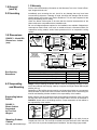
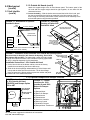
3.0 Dimensions
FIGURE 1 - Model RBL
Dimensions - inches
(mm)
2.0 Uncrating
Model RBL Air Openings (with duct ange) inches (mm)
Standard Horizontal Inlet Air Opening 19-1/2 x 47-5/8 495 x 1210
Optional Bottom Return Air Inlet Air Opening 19-1/2 x 47-5/8 495 x 1210
Standard Horizontal Discharge Air Opening 22-1/8 x 48-15/16 562 x 1243
Btm Discharge Air Opening w/Downturn Plenum Cabinet 19-1/2 x 47-5/8 495 x 1210
Immediately upon uncrating the unit, check for any damage that may have been
incurred during shipment. If damage is found, document the damage with the trans-
porting agency and contact your Reznor Distributor. This unit was inspected at the
factory immediately prior to crating.
Check the blower cabinet plate to be sure that the electrical characteristics of the
blower cabinet are compatible with the installation site.
Be sure all shipped-separate options for the installation are available. Shipped-sep-
arate options could include a roof curb, an outside air hood, a disconnect switch, an
evaporative cooling module, and/or freeze protection kit for an evaporative cooling
module.
1.0 General
(cont'd)
Duct Opening
Dimensions
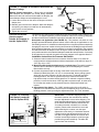
4.0 Suspending
and Mounting
FIGURE 2 -
Blower Cabinet
Suspended
by Four Rod
Hangers
Weight - Before installing the blower cabinet, check the supporting structure to verify
that it has sufcient load-carrying capacity to support the weight. Model RBL weighs
488 lbs (221 kg).
Depending on the building structure and its use, determine whether or not measures
should be taken to reduce the effect of blower vibration and/or noise. Determining the
need for and installing vibration isolation is the responsibility of the installer.
Suspending Indoor
Cabinet
Blower cabinets may be suspended using eld-furnished rod hangers. Insert 1/2" rods
into the holes at the corners of the curb cap. Attach rods to the unit as illustrated in
FIGURE 2. Attach rods to the building structure. Proper suspension of this cabinet is
the responsibility of the installer.
Mounting Outdoor
Cabinet
Model RBL blower cabinet is equipped with a load bearing curb cap which forms an
integral part of the unit. This curb cap is welded at all joints and has a "skirt" which ts
over a roof curb to provide a weatherproof installation. Use the lifting lugs provided.
1.3 Warranty
Refer to the limited warranty information on the Warranty Form in the "Owner's Enve-
lope" shipped with the unit.

Form I-RBL, P/N163219R2, Page 3
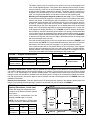
FIGURE 3 - Support Rail Dimensions
Conguration A B
Standard Model RBL 59-1/16" (1500mm) 53-9/16" (1361mm)
Model RBL with
Downturn Cabinet
82-1/16" (2084mm) 53-9/16" (1361mm)
Mounting on a Roof Curb - Whether using an optional roof curb available for the cabinet or a eld-supplied curb, the
curb must be square and level and a minimum height of 14" (356mm). The top surface of the roof curb must be caulked
with 1/4" x 1-1/4" sealant tape or 1/4" beads of suitable sealant. The cabinet must be sealed to the curb to prevent water
leakage into the curb area due to windblown rain and capillary action. Except for the curb assembly details, the informa-
tion and requirements in this section apply to both an optional curb and a eld-supplied curb. See FIGURE 5 and curb
installation instructions.
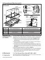
Bottom Duct Connections - Both the optional return air opening and the opening in the downturn plenum have duct
anges. Duct opening sizes and spacing in relation to an optional roof curb are shown in FIGURE 4.
The blower cabinet may be mounted on an optional roof curb, a eld-supplied roof
curb, or eld supplied supports. If the system has a downturn plenum and/or a bottom
return air opening, a roof curb is recommended to provide a weatherproof installation
as well as more workable clearances for ductwork. The blower cabinet curb cap is not
designed to be placed directly on the roof surface. When positioning rooftop equip-
ment, it is recommended that the air inlet does not face into the prevailing wind.
Mounting on Field Supplied Supports (without a roof curb) - Prior to installation,
be sure that the method of support is in agreement with all local building codes and is
suited to the climate. If considering this type of installation in snow areas, it is recom-
mended that the 4x4 wooden rails underneath the unit be on cross-support structure
at least 12" (305mm) higher than the roof surface. Whether the supports are being
mounted directly on the roof or being placed "up" on additional structure, the horizontal
length of the unit should be supported by two 4x4 treated wooden rails. Cut the rails
to the appropriate length (Dimension "A") in FIGURE 3. (NOTE: Although dimensions
are included for units with a downturn plenum cabinet, it is strongly recommended that
a roof curb be used on an installation with a downturn plenum cabinet and/or a bottom
return air duct.) Space the 4x4 wooden support rails (See "B" Dimension in FIGURE 3)
so that the curb cap "skirt" will t over the edge of the boards with the rail setting inside
the horizontal length of the curb cap.
If the rails are being laid directly on the roof, position them as shown in FIGURE 3. Set
the unit on the rails. NOTE: It is recommended that there be a minimum of 14" between
the bottom of the inlet air hood (see Paragraph 5.1.2) and the mounting surface.
If the treated wooden rails are not placed directly on the roof surface, cross supports
should be placed underneath the rails at the ends of the cabinet. The eld-supplied,
weather-resistant cross-support structure must be adequate for the weight of the unit
and run the entire width of the cabinet supporting the 4x4 wooden rails.
Dimensions G H
Standard RBL
Cabinet
NA
47-5/8"
(1210mm)
RBL w/Down-
turn Plenum
55-13/16"
(1418mm)
47-5/8"
(1210mm)
FIGURE 4 - Roof Curb and Optional Duct
Opening Dimensions - inches (mm)
Return and Supply Duct Dimensions and
Locations are in relation to Reznor Optional
Roof Curbs.)
1-5/8" (41mm) is measurement from duct
opening to inside edge of roof curb.
NOTE: Cut duct openings 1" (25mm) larger
than the duct size for installation clearance.

Form I-RBL, P/N163219R2, Page 4
4.0 Suspending and Mounting (cont'd)
* C and D are roof opening dimensions.
FIGURE 5 - Roof Curb Dimensions (inches/mm)
and Installation
Curb Section
Curb Corner Detail
Curb
Detail
See
FIGURE 5.
Model RBL without Optional Downturn
Plenum - Roof Curb Option CJ1
Model RBL with Optional Downturn Plenum Cabinet
(Option AQ5 or AQ8) - Roof Curb Option CJ2
A 59-1/16" (1500mm) 82-1/16" (2084mm)
B 53-9/16" (1361mm) 28-13/16" (732mm)
C* 55-5/16" (1405mm) 78-5/16" (1989mm)
D* 49-13/16" (1265mm) 49-13/16" (1265mm)
Optional Roof Curb
Installation Instructions
(See FIGURE 8)
Filter racks and lters are optional equipment. Filters are 2" and may be either dispos-
able, permanent aluminum, or pleated disposable.
5.0 Mechanical
5.1.1 Filter Rack and Filters, Option AW7, AW9, or AW11
The curb is shipped unassembled. Field assembly and mounting on the roof are the
responsibility of the installer. Hardware to assemble the corners is supplied, Before
installing the roof curb, verify that the size is correct for the cabinet being installed.
1. Position the curb cross rails and curb side rails as shown in FIGURE 5. Fasten
curbing pieces at all corners with bolts and lag screws as shown in the Corner
Detail illustration.
2. Check the assembly for squareness. Adjust the roof opening so that the diagonal
measurements are equal within a tolerance of ± 1/8" (3mm).
3. Level the roof curb. To ensure a good weathertight seal between the integral curb
cap and the roof curb, the roof curb must be leveled in both directions with no twist
end to end. Shim level as required and secure curb to roof deck before proceeding
with ashing.
4. Install eld-supplied ashing (See Curb Detail in FIGURE 5).
5. Before placing the unit on the curb, apply furnished 1/4" x 1-1/4" foam sealant tape
to the top surface of the curb, making good butt joint at the corners. The cabinet
must be sealed to the curb to prevent water leakage into the curb area due to
blown rain and capillary action.
5.1 Unit Inlet Air

Form I-RBL, P/N163219R2, Page 5
RBL
CFM
2" Disposable Filters
(Option AW7)
2" Permanent Filters
(Option AW9)
2" Pleated Filters
(Option AW11)
5000 0.04 0.08 0.10
6000 0.06 0.12 0.14
7000 0.08 0.16 0.19
8000 0.10 0.21 0.25
9000 0.13 0.26 0.31
10000 N/A 0.33 0.39
11000 N/A 0.40 0.47
12000 N/A 0.48 0.56
13000 N/A 0.56 N/A
14000 N/A 0.65 N/A
Disposable Filter Range --
0 to 400 FPM
Pleated Filter Range --
0 to 500 FPM
Permanent Aluminum Filter
Range -- 0 to 600 FPM
Disposable
Filters (Option
AW7)
Pleated Filters
(Option AW11)
Permanent Filters
(Option AW9)
NOTE: If the unit was manufactured prior to 9/91;
lter sizes and arrangements are different; refer to
Parts Replacement Form P-RG/RP/RBL or contact
your distributor.
Type of Filters Average Efciency Average Arrestance
Disposable 2" Less than 20% 80%
Permanent 2" Less than 20% 64% to 67%
Pleated Disposable 2" 30% to 35% 90% to 93%
A 16 x 16
B 16 x 25
C 12 x 25
D 12 x 30
A 16 x 16
B 16 x 25
C 12 x 16
D 12 x 26
A 16 x 16
B 16 x 25
C 12 x 25
D 12 x 32
FIGURE 6 - Filter Arrangements
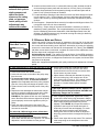
5.1.2 Outside Air
Hoods
100% Outside Air Hood, Option AS2 - Outside air hood (Option AS2) is a weather-
ized, screened hood designed to be eld assembled and installed around the horizon-
tal inlet air opening of the blower cabinet. The air hood includes a louver assembly
designed to help eliminate moisture from the inlet air. Complete installation instructions
are packaged with the air hood option.
CAUTION: It is recommended that the inlet to the outside air
hood NOT be facing into the prevailing wind. Allow 14" minimum
clearance from the bottom of the air hood to the mounting surface.
NOTE: Either a
manufacturer designed
optional air inlet hood as
shown in Paragraph 5.1.2
or an evaporative cooling
module as shown in
Paragraph 5.1.4 is required
to ensure complete weather
resistance.
Filter Pressure
Drops (" w.c.)
Installation Instructions - 100% Outside Air Hood (See FIGURE 7B)
To avoid possible damage, it is recommended that the outside air hood be installed
after the cabinet has been placed on the roof. The air hood should be installed before
the blower is operated. Do not install the hood while the blower is in operation. All
screw ends except those across the bottom are inside the air hood.
1. Top Panel -- On the air inlet side of the blower cabinet, remove the factory-
installed screws attaching the blower cabinet top. Slide the air hood top panel
underneath the edge of the blower cabinet top. The edge of the air hood top
panel must be between the blower cabinet top and the end panel. Reinsert all
of the sheetmetal screws.
2. Side Panels -- Slide the air hood right side panel into the groove in the blower
cabinet end panel. Be sure that the side panel is underneath and to the inside of
the air hood top panel. Attach to the blower cabinet and the air hood top using the
required number of sheetmetal screws. Repeat with the left side panel.
3. Bottom Panel -- Position the air hood bottom panel so that it is to the inside of the
two side panels and above the factory-installed support angle. Attach to the side
panels.
If the bottom panel does not rest tightly against the support angle, follow these
instructions to adjust the position of the support angle:
a) Slightly loosen (do not remove the screws).
b) Slide the support angle up so that it is against the bottom panel.
c) Tighten the screws.

Form I-RBL, P/N163219R2, Page 6
FIGURE 7B - Assembly
Drawing of Option AS2
Outside Air hood
FIGURE 7A - Dimensions of Optional
Outside Air Hood
(NOTE: The width of the outside air hood is the same
as the width of the blower cabinet.)
Screened Inlet Air Hood for 30% Outside Air Opening, Part of Inlet
Air Options AR6 and AR7) -The assembled outside air hood included
in the air inlet options that have a 30% outside air opening (Option AR6
or AR7) is shipped separately for eld installation.
Installation Instructions - 30% Outside Air Hood
1. On the inlet air side of the blower cabinet, remove the factory
installed screws attaching the blower cabinet top.
2. Slide the air hood top ange underneath the lip of the blower cabi-
net top and the sides into the vertical slots. The air hood ange
must be between the blower cabinet top and the cabinet end panel.
3. Reinsert all of the sheetmetal screws.
Width of
Outside
Air Hood
58-7/8"
1495mm
5.0 Mechanical
(cont'd)
5.1 Unit Inlet Air
(cont'd)
1) Damper Motor
2) Return Air Damper
3) Potentiometer
4) Potentiometer
5) Mixed Air Controller
6) Warm-up Control
7) Outside Air Damper
8) Damper Motor Transformer
FIGURE 9 - Location of Controls
for 30% Outside Air Hood
(FIGURE 8) and Damper Option
AR6 or AR7
FIGURE 10 - Control
Locations for 100%
Outside Air and 100%
Return Air Damper
Options
5.1.3 Optional Dampers and Damper Controls
NOTE: The illustrations in FIGURES 9 & 10 are intended to show location only of various air control accessories and
do not represent suggested combinations of accessories.
Attach the support angle to the air hood bottom panel. The bottom panel of the
air hood and the support angle should be tight together; do not draw with the
sheetmetal screws.
4. Louver Assembly -- With the intake screen toward the inside of the hood, posi-
tion the pre-assembled vertical louver assembly in the inlet opening of the air
hood. Using the remaining sheetmetal screws, attach the louver assembly to the
air hood side panels using the holes provided.
5.1.2 Outside Air Hoods (cont'd)
FIGURE 8 - Installation of Air Hood with 30% Outside Air Opening Option

Form I-RBL, P/N163219R2, Page 7
Outside Air
Damper
CLOSED
Return Air
Damper
OPEN
Rod for Outside
Air Damper
Set Screw
Outside Air
Damper Arm
Return Air
Damper Arm
Rod for Return
Air Damper
Damper
Motor
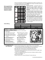
Damper Linkage Instructions -- When units are equipped
with dampers, the dampers are closed during shipment.
When there are both return air and outside air dampers, the
return damper linkage must be adjusted prior to use.
1. Loosen the set screw on the return air damper rod at the
damper arm.
2. Manually open the return air dampers. While the dampers
are opening, the damper rod and arm will automatically
move to their correct positions.
3. Tighten the set screw.
FIGURE 11 - Example of Outside Air and Return Air
Damper Linkage
Pressure Null Switch
(Used to control
Outside Air Dampers in
Inlet Air Option AR23)
The pressure null switch used in Option AR23 is a Dwyer #1640-0 with a range of .01-
.20" w.c. It is shipped separately for eld installation. Refer to the following paragraphs
and the manufacturer's installation instructions included with the switch.
Description and Application (See FIGURE 12) - The pressure null switch is a dia-
phragm operated differential pressure switch used in makeup air applications to con-
trol building pressure. It maintains a selected positive or negative pressure setpoint by
changing the amount of outside air being introduced to the building through the modu-
lating outside air dampers. As more pressure is required in the building, the pressure
null switch activates the damper motor driving the outside air damper towards the full
open position and the recirculated air damper towards the closed position. Conversely,
as less pressure is required, the switch drives the dampers in the opposite direction.
Installation Instructions for Pressure Null Switch
1. Select an indoor location free from excessive vibration where oil or water will
not drip onto the switch and where ambient temperature will be within a range of
-30°F (dry air) to 110°F.
2. Mount the switch with the diaphragm in a vertical plane. The switch is position
sensitive and is calibrated to operate properly when the diaphragm is vertical.
Mount switch securely.
3. Connect the pressure taps on the top of the switch to sources of air pressure
differential. Metal tubing with 1/4" O.D. is recommended, but any tubing system
which will not unduly restrict the air ow may be used. To maintain a positive
building pressure, vent the low pressure tap to the outdoors and allow the
high pressure tap to monitor building pressure. To maintain a negative building
pressure, reverse the functions of the high and low pressure taps. In either case,
be sure that the outdoor vent is protected from the wind and screened from
insects.
4. Adjustment of the Switch - The "HIGH" actuation point of the null switch is
indicated on a calibrated scale secured to the transparent range screw enclosure.
Building pressure is set by turning the adjustment screw. The "Low" actuation
IMPORTANT: To eliminate shipping damage to
the switch contacts, the manufacturer reduced
the span adjustment to zero before shipping. The
span should be adjusted prior to using the switch.
(If the switch has been installed, disconnect the
vent tube so that the null switch is in a neutral
position.) Remove the electrical box cover and
while observing the contacts, turn the span
adjustment screw slowly in a clockwise direction.
Continue turning the adjustment screw until you
are able to see gaps between the common and
both the low and high contacts. A minimum gap
provides the greatest sensitivity. The wider the
gap the lower the sensitivity.
FIGURE 12 - Pressure
Null Switch (used with
Inlet Air Option AR23)

Form I-RBL, P/N163219R2, Page 8
5.1.4 Optional Evaporative Cooling Module
Evaporative cooling provides comfort cooling at low initial equipment and installation
costs and low operating and maintenance costs. Direct evaporative cooling works
solely on the principle that water in direct contact with a moving airstream will eventu-
ally evaporate if the droplets have long enough exposure. This evaporative cooling
module uses wetted rigid cellulose or rigid glass ber media to retain water in order to
allow time for evaporation.
The evaporative cooling module for a Model RBL cabinet is factory assembled but
is not attached to the blower cabinet at the factory. It is shipped separately for eld
attachment to the system blower cabinet. The base support for the cooling module and
the transitional ductwork between the cooling module and the blower cabinet inlet are
shipped separately and must be eld assembled and installed. Installation instructions
including water and electrical connections are included with the evaporative cooling
module package.
Blower
Cabinet
Cooling
Module
and Base
FIGURE 13 - Optional
Evaporative Cooling
Module for Model RBL
Blower Cabinet is
factory-assembled for
eld attachment to the
blower cabinet (duct
and base are shipped
knocked down for eld
assembly)
NOTE: Evaporative cooling
module installation and
maintenance information is
in Form I-OPT-EC shipped
with the evaporative
cooling module. Follow
the instructions to install,
become familiar with the
maintenance requirements,
and keep Form I-OPT-EC
for future reference.
5.0 Mechanical
(cont'd)
5.1 Unit Inlet Air
(cont'd)
5.1.3 Optional Dampers and Damper Controls (cont'd)
point is set by adjusting the span of the null by turning the span adjustment screw.
The span range is .01 to .03" w.c.
5. Refer to the wiring diagram to make electrical connections.
5.2 Duct
Connections
NOTES: For systems with
a downturn cabinet, the
type of duct installation to
be used depends in part on
the type of construction of
the roof (whether wood joist,
steel bar joist, steel truss,
precast concrete) and the
ceiling (whether hung, ush,
etc.).
For cabinets without a downturn, a minimum horizontal duct run of 24 inches (610mm)
is recommended before turns or branches are made in the duct system, to reduce
losses at the furnace outlet.
Make certain return air ductwork and grills have a free area equal to the return duct
size connection. See Paragraph 3.0 for duct opening dimensions.
Suggestions for Installing Ducts
A. The type of duct installation to be used depends in part on the type of construction
of the roof (whether wood joist, steel bar joist, steel truss, precast concrete) and
the ceiling (whether hung, ush, etc.). Duct connections should be mechanical.
B. Rectangular duct should be constructed of not lighter than No. 26 U.S. gauge gal-
vanized iron or No. 24 B & S gauge aluminum.
C. All duct sections 24 inches (610mm) or wider, and over 48 inches (1219mm)
in length, should be cross broken on top and bottom and should have standing
seams or angle-iron braces. Joints should be S and drive strip, or locked.
Transition Duct
Included in the cooling module installation booklet is a preparation checklist. All items
in that checklist should be consulted prior to beginning installation of the optional evap-
orative cooling module. Four of those items are listed below.
Make certain the roof or platform is capable of handling the additional load of a full
cooling module reservoir.
Module with 12" rigid cellulose media (Option AS4) weighs 431 lbs.
Module with 12" rigid glass ber media (Option AS6) weighs 514 lbs.
Make certain the surface is level and free of debris where cooling module will be
mounted.
Do not mount directly on soft tar roofs where the legs could sink and tilt the cooler.
Provide a weather-resistant, solid wood or metal base under cooling module sup-
port legs.
Make certain that there will be adequate clearance between the bottom of the res-
ervoir and the roof (or platform) to allow for drain and overow pipe connections.

Form I-RBL, P/N163219R2, Page 9
CAUTION: An
external duct system
static pressure not
within the limits
shown on the rating
plate, or improper
motor pulley or belt
adjustment, may
overload the motor.
5.3 Blowers, Belts and Drives
Check belt tension. Proper belt tension is important to the long life of the belt and
motor. A loose belt will cause wear and slippage. Too much tension will cause exces-
sive motor and blower bearing wear. Adjust the belt tension by turning the adjusting
screw on the motor base until the belt can be depressed 3/4" (19mm). (See FIGURE
14.) After correct tension is achieved, re-tighten the locknut on the adjustment screw.
Be sure that the belt is aligned in the pulleys.
Adjusting Blower Speed - The system is set at the factory for the RPM required to
meet the CFM and external static pressure specied on the order. If estimated external
static pressure is incorrect, or changes were made to the duct system, the blower RPM
may have to be adjusted.
Motors are equipped with adjustable pitch pulleys which permit adjustment of blower
speed.
FIGURE 14 -
Check Belt Tension
D. No warm air duct should come in contact with masonry walls. Insulate around all
air ducts through masonry walls with not less than 1/2 inch (13mm) of insulation.
E. Insulate all exposed warm air ducts passing through an unheated space with at
least 1/2 inch (13mm) thickness of insulation.
F. For optional bottom openings, insert ducts from below roof deck through roof open-
ing into cabinet. Form 1" (25mm) anges, fold over, and fasten with sheetmetal
screws. Gain access by removing side panels from blower and downturn plenum
sections.
G. Duct Supports -- Suspend all ducts securely from adjacent buildings members. Do
not support ducts from unit duct connections.
H. Duct Sizing -- Proper sizing of the warm air ductwork is necessary to ensure a
satisfactory heating installation. The recognized authority for such information is
the Air Conditioning Contractors Association, 2800 Shirlington Road, Suite 300,
Arlington, VA 20036 (www.acca.org). A manual covering duct sizing in detail may
be purchased directly from them.
To make adjustments to units with less than a 5HP
motor, follow these instructions.
1. Loosen belt tension and remove the belt.
2. Loosen the set screw on the side of the pulley away
from the motor.
3. To increase the blower speed, turn the adjustable
half of the pulley inward. To decrease the blower
speed, turn the adjustable half of the pulley outward.
One turn of the pulley will change the speed 8-10%.
4. Tighten the set screw on the at portion of the pulley
shaft.
5. Replace the belt and adjust the belt tension. Adjust
tension by turning the adjusting screw on the motor
base until the belt can be depressed 3/4". (See
FIGURE 14.) Re-tighten the lock nut on the adjusting
screw. Be sure that the belts are aligned in the pulley
grooves properly and are not angled from pulley to
pulley.
6. Check the motor amps with an amp meter. The
maximum motor amp rating on the motor nameplate
must not be exceeded.
For units with 5 HP and larger motor, follow these
instructions for adjusting RPM:
1. Slack off all belt tension by moving motor towards
driven shaft until belts are free of grooves. For easiest
adjustment, remove the belts from the grooves.
2. On the outer locking ring, locate the two locking
screws that are directly across from each other.
Loosen these two screws, but do not remove them.
Do not loosen any other screws.
3. Adjust sheave to desired pitch diameter by turning
the outer locking ring. One complete turn of the
outer locking ring will result in .233" change in pitch
diameter. To decrease blower speed, increase
diameter; to increase blower speed, decrease
diameter.
CAUTION: Sheaves should not be adjusted in
either direction to the point where movable and
stationary anges are in contact.
4. After completing adjustment, tighten both locking
screws in the outer locking ring (loosened in Step 2).
5. Replace belts and move motor away from the driven
shaft to apply sufcient belt tension to prevent
slippage. (See FIGURE 14.) Proper belt tension is
important to the long life of the belt and motor. A
loose belt will cause wear and slippage. Too much
tension will cause excessive motor and blower
bearing wear. Be sure that the belts are aligned in
the pulley grooves and are not angled from pulley to
pulley.
6. Check motor amps with an amp meter. The maximum
motor amp rating on the nameplate must not be
exceeded.

Form I-RBL, P/N163219R2, Page 10
5.0 Mechanical (cont'd)
Blower Pulley - Some blower pulleys require the use of a split taper
bushing in the blower pulley. These split taper bushings must be loos-
ened in order to remove the pulley. Follow these instructions to loosen
the bushing:
a) Notice that there are three cap screws in the bushing and two holes
without screws, called push-off holes.
b) Remove the three cap screws.
c) Put two of the cap screws into the two push-off holes. Tighten these
two screws evenly until the pulley is loosened.
d) Pulley may now be removed from the shaft.
Blower Bearings - The blower bearings on systems with less than a 10 HP motor
(standard blower) are permanently lubricated cartridge ball bearings and do not require
greasing.
The blower bearings on systems equipped with 10-20 HP motor are pillow block ball
bearings and are equipped with a grease tting. (NOTE: Units manufactured prior
to 1/91 with a 10 HP motor may have permanently lubricated ball bearings.) These
bearings should be lubricated twice a year with a high temperature, moisture-resistant
grease. (Type NLGI-1 or -2 standard grease is recommended.) Be sure to clean the
grease tting before adding grease. Add grease with a handgun until a slight bead of
grease forms at the seal. Be careful not to unseat the seal by overlubricating. NOTE:
If unusual environmental conditions exist (temperatures below 32°F or above 200°F;
moisture; or contaminants), more frequent lubrication is required.
Blower Rotation - Each blower housing is marked for proper rotation. Rotation may be
changed on single-phase motors by re-wiring in the motor terminal box. Three-phase
motors may be reversed by interchanging two wires on the 3-phase supply connec-
tions.
FIGURE 15 - Split Taper Bushing
(3) Cap
Screws
(2) Push-
Off Holes
All electrical wiring and connections, including electrical grounding MUST be made in
accordance with the National Electric Code ANSI/NFPA No. 70 (latest edition) or, in
Canada, the Canadian Electrical Code, Part I-C.S.A. Standard C22.1. In addition, the
installer should be aware of any local ordinances or gas company requirements that
might apply.
Check the plate on the cabinet for the supply voltage and current requirements. A
separate line voltage supply with fused disconnect switch should be run directly from
the main electrical panel, making connection to leads in the junction box. All external
wiring must be within approved conduit and have a minimum temperature rise of 60°C.
Conduit from the disconnect switch must be run so as not to interfere with the service
panels of the cabinet. The unit must be electrically grounded in accordance with the
national Electrical Code, ANSI/NFPA No. 70 (latest edition or CSA Standard C22.1
when installed, if an external electrical source is used.
6.0 Electrical
Supply and
Connections
5.3 Blowers, Belts, and Drives (cont'd)
CAUTION: If any of
the original wire as
supplied with the
appliance must be
replaced, it must be
replaced with wiring
material having a tem-
perature rating of at
least 105°C.
If the installation includes eld-installed options that require electrical connections, con-
sult the instruction sheet and wiring diagram supplied in the option package. Optional
shipped-separate controls could include system switches, potentiometer, a pressure
null switch, or a combination of these controls. Install these according to the manufac-
turer's instructions packed with the cabinet.
Motors - Use an amp meter to check
motor amps. The chart below lists full load
amps for various HP and voltages. Amps
may be adjusted downward by reducing
blower RPM or by increasing duct system
static pressure.
This chart should not be interpreted as the
exact amps. See the motor rating plate for
specic amps.
Full Load Amps - Blower Motors (Open)
(Single Speed- Average Values)
HP 208/1 230/1 208/3 230/3 460/3 575/3
1 7.5 6.5 3.7 3.2 1.6 1.1
1-1/2 8.3 7.5 5.6 5.0 2.7 1.6
2 10.0 10.2 7.0 6.6 3.5 2.1
3 14.0 12.4 9.0 8.6 4.3 3.6
5 28.0 26.0 13.4 13.2 6.6 5.4
7-1/2 35.0 32.0 22.5 19.4 9.7 7.8
10 42.0 38.0 30.0 26.0 13.0 10.4
15 43.1 39.0 19.5 16.0
20 58.7 53.0 26.5 21.2
CAUTION: If the
blower is unused
for more than three
months, bearings
with a grease tting
should be purged
with new grease
prior to start-up.

Form I-RBL, P/N163219R2, Page 11
Voltage
/Phase
Motor
HP
Wire
Gauge
BX
Cable
208/1 or
230/1
1 - 2 14 3/8"
3 10 1/2"
5 8 1/2"
7.5 6 1"
10 4 1"
208/3 or
230/3
1 - 4 14 3/8"
5 12 3/8"
7.5 10 1/2"
10 8 1/2"
15 6 1"
20 4 1"
460/3
1 - 7-1/2 14 3/8"
10 12 3/8"
15 10 1/2"
20 8 1/2"
575/3
1 - 7-1/2 14 3/8"
10 - 20 10 1/2"
Field-supplied Wiring
Size from Disconnect
to Electrical Box for
Connection to Motor
Contactor or Starter
Disconnect Switch - A disconnect switch is a
required part of this installation. Switches are
available, as options or parts, or may be pur-
chased locally. When ordered as an optional
component, the disconnect switch is shipped
separately.
The disconnect switch may be fusible or non-fus-
ible. When installing, be careful that the conduit
and switch housing are clear of cabinet panels.
Allow at least four feet (1.2M) of service room
between the switch and removable panels.
Convenience Outlet Option - When a conve-
nience outlet (Option BC) is included, a separate
power supply must be provided to the receptacle.
This circuit MUST BE on a ground fault breaker to
meet requirements. All wiring to the convenience
outlet must meet National Electrical Code ANSI/
NFPA No. 70 (latest edition) and any local or util-
ity codes that apply.
Control Wiring
Field Control Wiring - Length and Gauge
Total Wire Length Distance from Unit to Control Minimum Recommended Wire Gauge
150 ft (46M) 75 ft (23M) #18 gauge
250 ft (76M) 125 ft (38M) #16 gauge
350 ft (107M) 175 ft (53M) #14 gauge
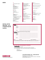
FIGURE 16 - Location of Electrical Connections and
Standard and Optional Controls
(Illustration is not an RBL cabinet but controls are in same location
in a Model RBL.)
1) Line Voltage Connection (eld)
2) Optional Convenience Outlet
3) Blower Motor Contactor or Starter
4) Optional Outside Air or Return Air
Controller
5) Optional Mixed Air Controller
6) Optional Potentiometer
7) Optional Potentiometer
8) Optional Return Air Dampers
9) Optional Filters
10) Optional Two-Position or
Modulating Damper Motor
11) Optional Outside Air Dampers
12) Blower Motor (Drive on opposite
Side) - Available in Open, TEFC,
Energy Efcient or Two-Speed
13) Optional Control Relays (as
required - 8 maximum)
14) Low Voltage Terminal Strip
15) Line Voltage Terminal Strip
16) Control Transformer
17) Control Transformer (as
required)
18) Optional Damper Motor
Transformer
19) Low Voltage Connection (eld)
7.0 Commissioning
and Start-Up
Be certain electrical supply matches voltage rating on unit (see rating plate).
Check all eld wiring against wiring diagram. Be sure wire gauges are as required
for the electrical load. This information appears on the wiring diagram.
Be certain that electrical entries are sealed against the weather.
See that fuses or circuit breakers are in place and sized correctly.
Check blower pulley and motor pulley to be sure they are secure to shafts. Check
belt tension; see Paragraph 5.3.
If the unit is equipped with outside air and return air dampers, adjust the damper
linkage. See Paragraph 5.1.3.
Close all panels tightly.
Return this book to the "Owner's Envelope" for future reference.
Check the wiring diagram and literature supplied with the cabinet for operation of fac-
tory-installed optional controls. See FIGURE 16 for location of electrical connections
and available standard and optional controls.

Form I-RBL, P/N163219R2, Page 12
INDEX
www.ReznorHVAC.com: 1-800-695-1901
©2014 Reznor, LLC. All rights reserved.
Trademark Note: Reznor
®
is registered in at least the United States.
0514 Form I-RBL (Version A.1)
Installer:
Name ________________________________________________________
Company ________________________________________________________
Address ________________________________________________________
________________________________________________________
________________________________________________________
Phone _________________________________
Distributor (company from which the unit was purchased):
Company ________________________________________________________
Contact ________________________________________________________
Address ________________________________________________________
________________________________________________________
________________________________________________________
Phone _________________________________
Model ___________ Serial No.___________________________Date of Installation ____________
SPECIFIC INSTALLATION NOTES: (i.e. Location, Amps, Voltage, Adjustments, Warranty, etc.)
____________________________________________________________________________________
____________________________________________________________________________________
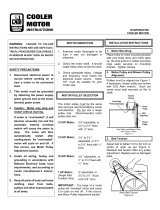
BUILDING OWNER OR MAINTENANCE PERSONNEL:
For service or repair
• Contact the installer listed above.
• If you need additional assistance, contact the Reznor Distributor listed above.
• For more information, contact your Reznor Representative by calling 800-695-1901.
Reznor, LLC
150 McKinley Avenue
Mercer, PA 16137
INSTALLATION
RECORD - to be
completed by the
installer:
A
Adjusting Blower Speed 9
B
Belts 9
Belt Tension 9
Blower Bearings 10
Blower Pulley 10
Blower Rotation 10
Blowers 9
C
CAUTION 1
Contact 12
Control Locations 6
D
Damper Linkage 7
DANGER 1
Dimensions 2
Dimensions of Optional Outside
Air Hood 6
Duct Opening Dimensions 2
Roof Curb Dimensions 4
Disconnect Switch 11
Distributor 12
Drives 9
Duct Connections 8
E
Electrical Connections 11
Electrical Supply and
Connections 10
Evaporative Cooling Module
(Optional) 8
F
Filter Arrangements 5
Filter Rack 4
Filters 4
G
General 1
H
Hazard labels 1
100% Outside Air Hood, Option
AS2 5
Outside Air Hood 5
Screened Air Hood for 30%
Outside Air Opening 6
I
INSTALLATION RECORD 12
Installer 12
M
Model 12
Motors 10
Mounting Outdoor Cabinet 2
O
30% Outside Air Hood (Optional)
6
Outside Air Hood (Optional) 5
P
Pressure Null Switch 7
R
Roof Curb 3, 4
S
Serial No. 12
Start-Up 11
Field Supplied Supports (without
a roof curb) 3
Suspending Indoor Cabinet 2
U
Uncrating 2
W
WARNING 1
Warranty 2
Wiring Size 11
-
 1
1
-
 2
2
-
 3
3
-
 4
4
-
 5
5
-
 6
6
-
 7
7
-
 8
8
-
 9
9
-
 10
10
-
 11
11
-
 12
12


Ask a question and I''ll find the answer in the document
Finding information in a document is now easier with AI
Related papers
Other documents
-
Unbranded High Static Blower Drive Kit Installation guide
-
DIAL 2201 Operating instructions
-
 Dial Manufacturing 2537 Installation guide
-
Franklin Brass 176-6 Installation guide
-
Crystal Distribution 19-999-3041 Installation guide
-
-
EZ-ACCESS TRAVERSE CP27 Operating instructions
-
Greenheck Fan GGH20 User manual
-
Aprilaire 2600 Owner's manual
-
Trane GRDA Installation, Operation and Maintenance Manual
