Specifications
Wingspan: 48 in (1200mm)
Length: 50 in (1250mm
Wing Area: 485 sq in (31.3 sq dm)
Weight w/o Battery: 3–3.3 lb (1.4–1.5 kg)
Weight w/ Battery: 3.6–4.2 lb (1.6–1.9 kg)
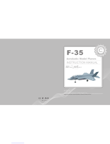
Diamante 25e ARF
Assembly Manual

2 E-flite Diamante 25e ARF Assembly Manual
Introduction
Thank you for purchasing the E-flite
®
Diamante 25e ARF.
The Diamante 25e was designed by champion pilot Peter
Goldsmith to provide intermediate to experienced pilots a
precision aerobatics platform that is excellently balanced
stability and has benign stall characteristics. At the heart of this
design is the SD8020 airfoil that provides excellent tracking
and crisp response in any axis. It is also extremely resistant
to accelerated stalls so you’ll feel like you’re on rails in any
attitude. Construction is balsa and light ply with a custom Peter
Goldsmith UltraCote
®
trim scheme. The fiberglass cowl and
wheel pants come painted from the factory. You will find two
sets of mounting holes on the firewall to mount your choice of
either the Power 25 or 32 Outrunner motors. The Power 32 is
recommended if you wish to fly aggressive artistic aerobatics
along with sport and precision flying. The Power 25 is ideal for
sport aerobatics.
This model was purposely designed for electric power
application from the ground up. The flight characteristics of this
design are such that it will reach a large cross section of skills.
Whether you are just learning to explore the aerobatic realm,
or a more experienced pilot, the Diamante 25e will touch
your skills with a low level of intimidation. The Diamante 25e
was designed to be a straightforward, pure flying aerobatic
performer. Much attention was spent developing the flight forces
in all 3 axes ensuring minimum coupling, meaning a lower
workload for the pilot.
Using the Manual
This manual is divided into sections to help make assembly
easier to understand, and to provide breaks between each
major section. In addition, check boxes have been placed next
to each step to keep track of each step completed. Steps with
a single circle (
) are performed once, while steps with two
circles (
) indicate that the step will require repeating, such
as for a right or left wing panel, two servos, etc.
Remember to take your time and follow the directions.
Table of Contents
Specifications .........................................................................1
Introduction ............................................................................2
Using the Manual ...................................................................
2
Contents of Kit/Parts Layout ....................................................
3
Required Radio Equipment ......................................................
3
Important Information About Motor Selection ...........................
3
Lightweight Sport Setup ..........................................................
4
Recommended High Power Precision Aerobatic Setup ..............
4
Alternative Sport andPrecision Setup .......................................
4
Optional Accessories ..............................................................
4
Note on Lithium Polymer Batteries ...........................................
4
Required Tools and Adhesives .................................................
5
Warning ................................................................................5
Warranty Period ....................................................................
5
Limited Warranty ...................................................................
6
Damage Limits .......................................................................
6
Safety Precautions ..................................................................
6
Questions, Assistance, and Repairs .........................................
7
Inspection or Repairs ..............................................................
7
Warranty Inspection and Repairs ............................................
7
Non-Warranty Repairs ...........................................................
7
Safety, Precautions, and Warnings ..........................................
8
Aileron Installation .................................................................
8
Landing Gear Installation ......................................................
14
Horizontal and Vertical Tail Installation ..................................
17
Motor Installation .................................................................
24
Final Assembly .....................................................................
27
Control Throws .....................................................................
28
Center of Gravity .................................................................
29
Range Test Your Radio ..........................................................
29
Preflight ...............................................................................29
Flying the Diamante 25e .......................................................
30
Reduce Your Workload .........................................................
30
Servo and Control Setup .......................................................
31
Sequencing ..........................................................................32
Balance ...............................................................................32
Dynamic Balance .................................................................
33
Thrust Angles .......................................................................
33
Differential ...........................................................................34
Programmable Mixing ..........................................................
35
2007 Official AMA National Model Aircraft Safety Code ......
38
Building and Flying Notes .....................................................
39

3E-flite Diamante 25e ARF Assembly Manual
Contents of Kit/Parts Layout
Large Replacement Parts
EFL4051 Wing w/Ailerons:
EFL4052 Fuselage
EFL4053 Tail Set
EFL4055 Main Landing Gear
EFL4056 Cowling
EFL4057 Wheel Pants
EFL4058 Canopy
EFL4059 Spinner
Small Replacement Parts
EFL4054 Pushrod Set
EFLA213 E-flite/JR/Horizon Decals
Required Radio Equipment
You will need a minimum 6-channel transmitter, crystals, micro
receiver, and four mini servos. You can choose to purchase
a complete radio system that includes all of these items or, if
you are using an existing transmitter, just purchase the other
required equipment separately.
Note: We recommend the crystal-free, interference-free
Spektrum
®
DX7 2.4GHz DSM
®
2 7-channel radio. The
complete system includes standard servos, which are not
required for the Diamante.
Purchase Separately
SPM6070 DSM2 7-Channel Receiver
Or
JRPR720 7-Channel ScanSelect
™
FM Receiver
Or
JRPR790 7-Channel ScanSelect PCM Receiver
JSP98110 6" Servo Extension (2)
JSP20040 MN48 Mini Servo (4)
JSP98020 Y-harness, Standard 6"
Note: When using our recommended E-flite 60A Pro
Brushless ESC with switching BEC you do not need a
separate receiver pack as long as you are using our
recommended servos.
Note: Depending on what speed control you are using,
if it is not capable of supporting four mini-size servos
because of current draw, the speed control may shut
down due to high heat.
In order to provide the most reliable product, E-flite
recommends the use of a separate BEC (like the Ultimate
BEC), or receiver pack and switch using the following
items to ensure trouble-free operation:
EXRB100 Expert 720mAh Ni-MH 4.8V Rx Pack
EXRA050 Expert Standard Switch

4 E-flite Diamante 25e ARF Assembly Manual
Important Information About Motor
Selection
The Diamante 25e does not include a propeller. We are
recommending the Power 25 or Power 32 outrunner motors.
The motor systems listed will provide you with excellent
aerobatic power for sport and/or artistic aerobatic pilots. All
power systems listed include worry-free outrunner motors.
Lightweight Sport Setup
EFLM4025A Power 25 BL Outrunner, 870Kv
EFLA1060 60A Pro Brushless ESC w/Switching BEC
THP42003S2PPL 4200mAh 3S2P 11.1V Li-Po, 13GA
APC12080E Electric Propeller, 12x8E
EFLC3005 Celectra 1- to 3-cell Li-Po Charger
EFLAEC303 EC3 Dev & Batt, Male/Female
This is a sport aerobatic setup with limited precision capabilities.
Recommended High Power
Precision Aerobatic Setup
EFLM4032A Power 32 BL Outrunner, 770Kv
EFLA1060 60A Pro Brushless ESC w/Switching BEC
THP42004S2PPL 4200mAh 4S2P 14.8V Li-Po, 13GA
APC13065E Electric Propeller, 13x6.5E
EFLAEC303 EC3 Dev & Batt, Male/Female
This is our recommended setup. Expect high power precision
aerobatics and very strong aggressive artistic aerobatics
performance.
Alternative Sport and
Precision Setup
EFLM4032A Power 32 BL Outrunner, 770Kv
THP42003S2PPL 4200mAh 3S2P 11.1V Li-Po, 13GA
APC14070E Electric Propeller, 14x7E
Or
EFLM4025A Power 25 BL Outrunner, 870Kv
THP42004S2PPL 4200mAh 4S2P 14.8V Li-Po, 13GA
APC12060E Electric Propeller, 12x6E
And
EFLA1060 60A Pro Brushless ESC w/Switching BEC
EFLAEC303 EC3 Dev & Batt, Male/Female
This is an alternative sport and precision aerobatic setup and
is a good option if you have some equipment and do not
want to purchase additional. Both options are very similar in
performance; you should expect better performance than our
lightweight sport setup and less performance than with our
recommended high power precision setup.
Optional Accessories
EFLA110 Power Meter
HAN172 Hangar 9 Digital Servo and
Rx Current Meter
Note on Lithium Polymer Batteries
Lithium Polymer batteries are significantly more
volatile than alkaline or Ni-Cd/Ni-MH batteries used
in RC applications. All manufacturer’s instructions
and warnings must be followed closely. Mishandling
of Li-Po batteries can result in fire. Always follow the
manufacturer’s instructions when disposing of Lithium
Polymer batteries.

5E-flite Diamante 25e ARF Assembly Manual
Required Tools and Adhesives
Tools & Equipment
EFLA250 Park Flyer Tool Assortment, 5-piece
Or Purchase Separately
EFLA257 Screwdriver, #0 Phillips (or included
with EFLA250)
EFLA251 Hex Wrench: 3/32", 7/64" (or
included with EFLA250)
Nut driver: 5/16"
Drill
Drill bit: 1/16" (1.5mm), 5/64" (2mm),
9/64" (3.5mm), 1/4" (6mm)
Hobby knife
Felt-tipped pen
Pliers
Rotary tool
T-pins
String
Thin CA
Weight
Pen Drill
Threadlock
#1 Phillips screwdriver
6-minute epoxy
Paper towel
Rubbing alcohol
Petroleum jelly
Canopy glue
Square
Sandpaper
Masking tape
Warning
An RC aircraft is not a toy! If misused, it can cause serious
bodily harm and damage to property. Fly only in open areas,
preferably at AMA (Academy of Model Aeronautics) approved
flying sites, following all instructions included with your radio.
Keep loose items that can get entangled in the propeller away
from the prop, including loose clothing, or other objects such as
pencils and screwdrivers. Especially keep your hands away from
the propeller.
Warranty Period
Horizon Hobby, Inc., (Horizon) warranties that the Products
purchased (the “Product”) will be free from defects in materials
and workmanship at the date of purchase by the Purchaser.

6 E-flite Diamante 25e ARF Assembly Manual
Limited Warranty
(a) This warranty is limited to the original Purchaser
("Purchaser") and is not transferable. REPAIR OR REPLACEMENT
AS PROVIDED UNDER THIS WARRANTY IS THE EXCLUSIVE
REMEDY OF THE PURCHASER. This warranty covers only those
Products purchased from an authorized Horizon dealer. Third
party transactions are not covered by this warranty. Proof of
purchase is required for warranty claims. Further, Horizon
reserves the right to change or modify this warranty without
notice and disclaims all other warranties, express or implied.
(b) Limitations- HORIZON MAKES NO WARRANTY OR
REPRESENTATION, EXPRESS OR IMPLIED, ABOUT NON-
INFRINGEMENT, MERCHANTABILITY OR FITNESS FOR A
PARTICULAR PURPOSE OF THE PRODUCT. THE PURCHASER
ACKNOWLEDGES THAT THEY ALONE HAVE DETERMINED
THAT THE PRODUCT WILL SUITABLY MEET THE REQUIREMENTS
OF THE PURCHASER’S INTENDED USE.
(c) Purchaser Remedy- Horizon's sole obligation hereunder
shall be that Horizon will, at its option, (i) repair or (ii)
replace, any Product determined by Horizon to be defective.
In the event of a defect, these are the Purchaser's exclusive
remedies. Horizon reserves the right to inspect any and all
equipment involved in a warranty claim. Repair or replacement
decisions are at the sole discretion of Horizon. This warranty
does not cover cosmetic damage or damage due to acts of
God, accident, misuse, abuse, negligence, commercial use,
or modification of or to any part of the Product. This warranty
does not cover damage due to improper installation, operation,
maintenance, or attempted repair by anyone other than
Horizon. Return of any goods by Purchaser must be approved
in writing by Horizon before shipment.
Damage Limits
HORIZON SHALL NOT BE LIABLE FOR SPECIAL, INDIRECT
OR CONSEQUENTIAL DAMAGES, LOSS OF PROFITS OR
PRODUCTION OR COMMERCIAL LOSS IN ANY WAY
CONNECTED WITH THE PRODUCT, WHETHER SUCH CLAIM IS
BASED IN CONTRACT, WARRANTY, NEGLIGENCE, OR STRICT
LIABILITY. Further, in no event shall the liability of Horizon
exceed the individual price of the Product on which liability
is asserted. As Horizon has no control over use, setup, final
assembly, modification or misuse, no liability shall be assumed
nor accepted for any resulting damage or injury. By the act of
use, setup or assembly, the user accepts all resulting liability.
If you as the Purchaser or user are not prepared to accept the
liability associated with the use of this Product, you are advised
to return this Product immediately in new and unused condition
to the place of purchase.
Law: These Terms are governed by Illinois law (without regard to
conflict of law principals).
Safety Precautions
This is a sophisticated hobby Product and not a toy. It must be
operated with caution and common sense and requires some
basic mechanical ability. Failure to operate this Product in a safe
and responsible manner could result in injury or damage to the
Product or other property. This Product is not intended for use
by children without direct adult supervision. The Product manual
contains instructions for safety, operation and maintenance. It is
essential to read and follow all the instructions and warnings in
the manual, prior to assembly, setup or use, in order to operate
correctly and avoid damage or injury.

7E-flite Diamante 25e ARF Assembly Manual
Questions, Assistance, and Repairs
Your local hobby store and/or place of purchase cannot provide
warranty support or repair. Once assembly, setup or use of the
Product has been started, you must contact Horizon directly.
This will enable Horizon to better answer your questions and
service you in the event that you may need any assistance.
For questions or assistance, please direct your email to
productsupport@horizonhobby.com, or call 877.504.0233 toll
free to speak to a service technician.
Inspection or Repairs
If this Product needs to be inspected or repaired, please call for
a Return Merchandise Authorization (RMA). Pack the Product
securely using a shipping carton. Please note that original boxes
may be included, but are not designed to withstand the rigors
of shipping without additional protection. Ship via a carrier that
provides tracking and insurance for lost or damaged parcels, as
Horizon is not responsible for merchandise until it arrives and
is accepted at our facility. A Service Repair Request is available
at www.horizonhobby.com on the “Support” tab. If you do not
have internet access, please include a letter with your complete
name, street address, email address and phone number where
you can be reached during business days, your RMA number,
a list of the included items, method of payment for any non-
warranty expenses and a brief summary of the problem.
Your original sales receipt must also be included for warranty
consideration. Be sure your name, address, and RMA number
are clearly written on the outside of the shipping carton.
Warranty Inspection and Repairs
To receive warranty service, you must include your original
sales receipt verifying the proof-of-purchase date. Provided
warranty conditions have been met, your Product will be
repaired or replaced free of charge. Repair or replacement
decisions are at the sole discretion of Horizon Hobby.
Non-Warranty Repairs
Should your repair not be covered by warranty the repair
will be completed and payment will be required without
notification or estimate of the expense unless the expense
exceeds 50% of the retail purchase cost. By submitting the item
for repair you are agreeing to payment of the repair without
notification. Repair estimates are available upon request. You
must include this request with your repair. Non-warranty repair
estimates will be billed a minimum of ½ hour of labor. In
addition you will be billed for return freight. Please advise us
of your preferred method of payment. Horizon accepts money
orders and cashiers checks, as well as Visa, MasterCard,
American Express, and Discover cards. If you choose to pay
by credit card, please include your credit card number and
expiration date. Any repair left unpaid or unclaimed after 90
days will be considered abandoned and will be disposed of
accordingly.
Please note: non-warranty repair is only available
on electronics and model engines.
Electronics and engines requiring inspection or repair should be
shipped to the following address:
Horizon Service Center
4105 Fieldstone Road
Champaign, Illinois 61822
All other Products requiring warranty inspection or repair should
be shipped to the following address:
Horizon Product Support
4105 Fieldstone Road
Champaign, Illinois 61822
Please call 877-504-0233 with any questions or concerns
regarding this product or warranty.

8 E-flite Diamante 25e ARF Assembly Manual
Safety, Precautions, and Warnings
As the user of this product, you are solely responsible for
operating it in a manner that does not endanger yourself
and others or result in damage to the product or the property
of others.
Carefully follow the directions and warnings for this and any
optional support equipment (chargers, rechargeable battery
packs, etc.) that you use.
This model is controlled by a radio signal that is subject to
interference from many sources outside your control. This
interference can cause momentary loss of control so it is
necessary to always keep a safe distance in all directions
around your model, as this margin will help to avoid collisions
or injury.
• Always operate your model in an open area away from cars,
traffic, or people.
• Avoid operating your model in the street where injury or
damage can occur.
• Never operate the model out into the street or populated
areas for any reason.
• Never operate your model with low transmitter batteries.
• Carefully follow the directions and warnings for this and any
optional support equipment (chargers, rechargeable battery
packs, etc.) that you use.
• Keep all chemicals, small parts and anything electrical out of
the reach of children.
• Moisture causes damage to electronics. Avoid water exposure
to all equipment not specifically designed and protected for
this purpose.
Aileron Installation
Required Parts
• Wing • Receiver
• Servo w/hardware (2) • Long servo arm (2)
• CA hinge (8) • 3
3
/
8
in (86mm) pushrod wire (2)
• Clevis (2) • Clevis retainer (2)
• Nylon control horn (2) • 3mm x 30mm machine screw (2)
• Control horn standoff (2) • Control horn washer (2)
• Puhrod wire connector (2)
• Servo extension, 6 in (152mm) (2)
Required Tools and Adhesives
• Rotary tool • Drill bit: 1/16 in (1.5mm)
• T-pins • Thin CA
• String • Weight
• Felt-tipped pen • Pen drill
• Threadlock • Tape
• #1 Phillips screwdriver
1. Locate four CA hinges. Place a T-pin in the center of
each hinge.

9E-flite Diamante 25e ARF Assembly Manual
2. Use a rotary tool and a 1/16 in (1.5mm) drill bit to
drill a hole in the center of each hinge slot of both the
aileron and wing. This provides a tunnel for the CA to
wick into, penetrating the hinge.
Hint: You can prepare the rudder, fin, elevator and
stabilizer at this time as well.
3. Slide the four hinges into the slots in the aileron.
4. Slide the aileron into position on the wing. The
T-pins installed back in Step 1 will help in keeping
equal amounts in the wing and aileron.

10 E-flite Diamante 25e ARF Assembly Manual
5. Apply a few drops onto each hinge. Make sure to
apply the CA on both the top and bottom of the hinge.
Important: Do not use accelerator on the hinges. The CA
must be allowed to soak in and penetrate the hinge.
6. Gently pull the aileron from the wing once the CA has
fully cured. This is to verify the hinges are glued securely.
7. Flex the aileron through its range of motion a few
times to break in the hinges.
8. Repeat Steps 1 through 7 to complete the
aileron installation.

11E-flite Diamante 25e ARF Assembly Manual
9. Install the servo grommets and brass eyelets onto the
aileron servo following the instructions provided with
the servo. Attach a 6 in (152mm) servo extension to the
aileron servo. Use a commercially available clip to keep
the two from becoming disconnected inside the wing.
10. Tie the string to the extension installed on the aileron
servo. Pull the extension through the wing and out the
hole in the center. Use tape to secure the extension to the
wing and prevent it from falling back into the wing.

12 E-flite Diamante 25e ARF Assembly Manual
11. Place the servo into the opening in the wing. Use
a felt-tipped pen to mark the locations for the servo
mounting screws.
12. Use a pen drill and 1/16 in (1.5mm) drill bit to drill
the four locations for the servo mounting screws.
13. Apply a few drops of thin CA to each of the four
holes. This will harden the underlying wood and help
in preventing the screws from pulling out.
14. Secure the servo in the wing using the screws
provided with the servo. Note the servo horn faces
towards the aileron.

13E-flite Diamante 25e ARF Assembly Manual
15. Use a hobby knife to pierce the covering for the
3mm x 30mm machine screw. Slide the screw into the
hole from the top of the wing. Slide a control horn
washer onto the screw, then thread the control horn
standoff onto the screw. Use a #1 Phillips screwdriver to
tighten the assembly.
Note: Use threadlock on the screw to prevent it from
vibrating loose.
16. Thread the nylon control horn onto the control
horn screw until the top of the horn is flush with the
top of the screw.
17. Slide a clevis retainer onto a nylon clevis. Thread the
clevis onto the
3
3
/
8
in (86mm) pushrod wire. Attach the
clevis to the control horn and slide the clevis retainer over
the forks of the clevis to secure it to the control horn.

14 E-flite Diamante 25e ARF Assembly Manual
18. Plug the servo into the receiver and power up the
radio system. Center the aileron stick and trim. Install
a long servo arm onto the servo, parallel to the aileron
hinge line. Mark the pushrod wire where it crosses the
servo horn using a felt-tipped pen.
19. Bend the wire 90 degrees at the mark made in the
last step. Use a pushrod wire connector to secure the wire
to the servo arm. Trim any excess wire using side cutters.
20. Repeat Steps 9 through 19 to complete the
aileron servo installation.
Landing Gear Installation
Required Parts
• Fuselage • Landing gear (left and right)
• 2
1
/
4
in (57mm) wheel (2) • Wheel pant (left and right)
• 6-32 lock nuts (6) • 6-32 x 1
1
/
8
" machine screw (2)
• #6 washer (4) • 4-40 x 1/2" machine screw (2)
• 4-40 blind nut (2)
• 6-32 x 3/8" socket head screws (4)
Required Tools and Adhesives
• Drill • Drill bit: 9/64 in (3.5mm)
• Adjustable wrench • Adjustable pliers
• #1 Phillips screwdriver • Hex wrench: 3/32", 7/64"
• Felt-tipped pen
1. Attach the landing gear to the bottom of the fuselage
using four 6-32 x 3/8" socket head screws. The gear will
only go on in one direction.

15E-flite Diamante 25e ARF Assembly Manual
2. Slide the 6-32 x 1
1
/
8
" machine screw through the
bottom hole of the landing gear. Secure the screw using a
6-32 lock nut. Thread a second lock nut onto the screw.
3. Slide a #6 washer onto the screw, then slide the wheel
onto the screw. Slide a second #6 washer onto the screw
and secure the wheel using a 6-32 lock nut. Make sure
the wheel can turn freely after installing the final nut.
4. Test fit the wheel pant onto the landing gear. Sand the
notch in the wheel pant if necesary so it fits over the lock
nut that is against the landing gear.
5. Position the wheel pant so it is parallel to the top of the
fuselage as shown.

16 E-flite Diamante 25e ARF Assembly Manual
6. Use a felt-tipped pen to transfer the location of the
upper hole onto the wheel pant.
7. Use a drill and 9/64 in (3.5mm) drill bit to drill the
location made in the previous step.
8. Press the 4-40 blind nut into the hole from the inside
of the wheel pant.
9. Slide the wheel pant back onto the gear and secure
using a 4-40 x 1/2" machine screw.
10. Repeat Steps 2 through 9 to install the remaining
wheel and wheel pant.

17E-flite Diamante 25e ARF Assembly Manual
Horizontal and Vertical Tail Installation
Required Parts
• Wing assembly • 10-32 nylon wing bolt
• Elevator • Pushrod wire connector (2)
• Stabilizer • Fin
• Rudder • CA hinges (9)
• 7 in (178mm) pushrod wire • 6
1
/
4
in (159mm) pushrod wire
• Clevis (2) • Clevis retainer (2)
• Nylon control horn (2) • 3mm x 30mm machine screw (2)
• Control horn standoff (2) • Control horn washer (2)
• Long servo horn (2) • Tail gear assembly
• 1 in (25mm) tail wheel • 3/32" wheel collar (2)
• Servo extension, 12" (305mm) (2)
• 1
1
/
4
in x 1/4 in (32mm x 6mm) wing dowel (2)
Required Tools and Adhesives
• Drill • Drill bit: 1/4 in (6mm)
• 6-minute epoxy
• Ruler • String
• Thin CA • T-pins
• Paper towel • Rubbing alcohol
• Hobby knife • Felt-tipped pen
• Petroleum jelly
1. Enlarge the holes in the leading edge of the wing
using a drill and 1/4 in (6mm) drill bit.
2. Use 6-minute epoxy to glue the 1
1
/
4
in x 1/4 in
(32mm x 6mm) wing dowels into the leading edge of
the wing. Clean up any excess epoxy using a paper
towel and rubbing alcohol. The dowels will protrude
3/8 in (10mm) forward of the wing.

18 E-flite Diamante 25e ARF Assembly Manual
3. Attach the wing to the fuselage using the 10-32 nylon
wing bolt.
4. Use six CA hinges to attach the elevator and
stabilizer. Use the same technique as the aileron
hinges when installing the elevator hinges.
5. Install the elevator control horn as shown following
the same technique as the aileron control horn. Note the
position of the control horn.
6. Slide the stabilizer into the fuselage. Make sure the
control horn faces toward the bottom of the fuselage.
Measure the distance from the center of the fuselage to
each stabilizer tip to center the stabilizer in the fuselage.

19E-flite Diamante 25e ARF Assembly Manual
7. Measure from the wing tip to the stabilizer to make
sure both measurements are equal. This will square the
stabilizer to the wing and fuselage. Use a piece of string
to check the distance between the wing and stabilizer.
8. Check to make sure the stabilizer is parallel to the
wing. Lightly sand the fuselage where the stabilizer rests
to correct any alignment problems.
9. Use a felt-tipped pen to trace the outline of the
fuselage on the top and bottom of the stabilizer once
the stabilizer has been aligned.

20 E-flite Diamante 25e ARF Assembly Manual
10. Use a hobby knife with a new blade to remove
the covering slightly inside the lines drawn in the
previous step.
Note: Remove the covering from the top and bottom of
the stabilizer.
Important: Use light pressure to remove the covering, as
you can use too much pressure and score the stabilizer
which could cause it to fail in flight.
Hint: You can use a soldering iron or hot knife as an
option to a hobby knife. This will greatly lower the
chances of cutting into the stabilizer.
11. Slide the stabilizer back into the fuselage and
double-check the alignment. Wick thin CA into the joint
between the fuselage and stabilizer. Avoid using CA
accelerator on the CA to give it time to wick into the joint.
Allow the CA to cure before handling the fuselage.
12. Locate the tail gear assemble and apply a thin
coat of petroleum jelly to the wire. Work the bushing to
distribute the jelly.
Page is loading ...
Page is loading ...
Page is loading ...
Page is loading ...
Page is loading ...
Page is loading ...
Page is loading ...
Page is loading ...
Page is loading ...
Page is loading ...
Page is loading ...
Page is loading ...
Page is loading ...
Page is loading ...
Page is loading ...
Page is loading ...
Page is loading ...
Page is loading ...
Page is loading ...
Page is loading ...
/