Page is loading ...

www.altronics.com.au
User manual revision number: 1.1 20 /02/2015
Operating Manual
A 4488 Paging Console
A 4489 Audio Switcher
Redback® Proudly Made In Australia
Distributed by Altronic Distributors Pty. Ltd.
Phone: 1300 780 999 Fax: 1300 790 999 Internet: www.altronics.com.au
OVERVIEW
The A 4488 paging microphone is a simple to use and elegant desk top design which provides up to 4 zones of paging. It
allows the operator to manually select any zone or any combination of zones. Also included is an All Call & Cancel button.
A pre-announcement chime is available at the paging console and through the PA system. Both of these are set by DIP
switches on the rear of the unit. Provision has also been made on the rear of the unit for a 3.5mm BGM input for
background music.
A maximum of two paging consoles can be connected to the A 4489 Audio Switcher at the same time. These work in a
“rst in, best dressed” arrangement. Each unit must be assigned an ID number through DIP switch settings on the rear of
the unit.
The A 4489 Audio Switcher provides a Microphone level or Line level output which can be connected directly to the inputs
of up to four ampliers to provide up to four zones of audio. Connection between the A 4488 and A 4489 is via a Cat5e
cable which carries power and the balanced audio output from the microphone.
Features
• Four zones of paging. • High level balanced output via Cat 5 cable
• 3.5mm BGM input on rear • 24V DC power supplied via Cat 5 cable *
• Pre-announcement chime. • Chime volume adjustment
• Mic volume adjustment • BGM volume adjustment

www.altronics.com.auRedback® Proudly Made In Australia
2
Fig 1a
Fig 2
1 2 3
6
7
24VDC In
Volume
Mic
Chime
Volume
1 2 3 4
1
2
PA System Chime On
SW
PA System Chime O
Internal Chime On Internal Chime O
On
O
DIP Switches 1-2 Settings
ON
1 2 3 4
BGM
Volume
BGM
Input
4
5
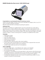
DIP Switch Settings
DIP switch 1 sets the pre-announcement chime on or off.
DIP switch 2 Not Used.
DIP switch 3 Not Used
DIP switch 4 sets the paging console ID number.
NOTE: The ID must be set when both consoles are being used.
IMPORTANT NOTE:
Ensure power is switched off when adjusting DIP switches.
New settings will be effective when power is switched back on.
A 4488 Rear Panel Connections
1 24V DC connector
2.1mm DC jack (centre pin positive).
2 RJ45 connector
For connection back to the A 4487.
Either port can be used.
3 DIP switch options
These switches set the chime options.
4 BGM (Background Music) Input
The background music can be connected via
a 3.5mm Stereo Jack.
5 BGM volume
Use this volume to adjust the background music
level.
6 Chime volume
Use this volume to adjust the chime level.
7 Microphone volume
Use this volume to adjust the microphone level.
1
2
Pre-announce Chime On
SW
Not used
On
O
DIP Switches 1-4 Settings
Pre-announce Chime O
3 Not used
4
Console ID =1 Console ID =2
To Paging Consoles
24V
DC IN
www.altronics.com.au
Manufactured in Australia By
+
-
Altronic Distributors Pty. Ltd.
+
-
Audio In
+-
+-+-
+-
+-
+-
Zone1Zone2Zone3Zone 4Mic OutLine Out
1 2
3
4
5
6
7
8
9
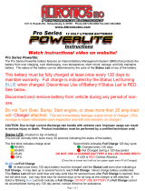
Fig 1b
A 4489 Rear Panel Connections
1 24V DC connector
2.1mm DC jack (centre pin positive).
2 RJ45 connector
For connection back to the A 4488 paging consoles. Either port can be used.
3 Line Out
This is the line level audio output from the paging console/s.
4 Mic Out
This is the low level audio output from the paging console/s.
5-8 Zone 1-4 Audio Outputs
These are switched audio outputs which output the signal present at the “Audio In” terminals when the particular
zone is triggered by a paging console.
9 Audio In
This is the input used to supply audio to the zone outputs.

www.altronics.com.au Redback® Proudly Made In Australia
3
Connecting the Paging Console/s and Audio Switcher
The Paging console/s and Audio Switcher are connected by a CAT5e cables with a maximum run distance of 300 metres.
This CAT5e cable can be connected to either of the two RJ45 ports provided on the rear of the microphone. A 24V DC
power supply rated at a minimum of 1A is required to power the system. Power connection must be made by connecting
power to the Audio Switcher via a 2.1mm DC Jack. Power is then fed through the CAT5e cables to supply power to the
paging consoles. We recommend tting the power supply with the Altronics P 0602 2.1mm DC Plug with collar which can
be screwed onto the DC socket to prevent accidental disconnection of power.
The balanced audio output from the microphone is transmitted down the CAT5e cable to the Audio Switcher which splits
and converts the signal to microphone and line level outputs. These are provided as screw terminal connections.
Volume controls for the microphone volume and chime volume are located on the rear of the microphone.
Connection Congurations
There are three basic different congurations for switching the audio output from the A 4489 Audio Switcher to the
output zones.
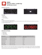
Option 1 : Individual Zone Ampliers using Microphone Level Signals
The audio from the paging console/s is fed down the Cat5e cable to the A 4489 audio switcher. Take the low level
balanced signal from the “Mic Out” terminals on the rear of the A 4489 and feed them back into the “Audio In”
terminals on the rear of the A 4489 as shown in Fig 3.
The audio from the “Zone 1” to “Zone 4” terminals are then fed into individual amplifers to provide the audio for the
four zones. The audio from these output terminals are switched internaly by relays and are not present unless the zone is
activated by the paging console/s.
Use this method if using ampliers with low level balanced inputs. If the ampliers used have line level inputs use the
conguration outlined in option 2.
CAT5 cable
Max 300M
MIC LEVEL SIGNAL
Typical connection of the A 4488/s and A 4489 with individual ampliers for each zone using mic levels
4 Zone Communicator
System Busy
Page
Lock On
All Call Cancel
A 4488
To Paging Consoles
24V
DC IN
www.altronics.com.au
Manufactured in Australia By
+-
Altronic Distributors Pty. Ltd.
+
-
Audio In
+-
+-+-
+-
+-
+-
Zone1Zone2Zone3Zone 4Mic OutLine Out
4 Zone Communicator
System Busy
Page
Lock On
All Call Cancel
A 4488
240V AC @ 50Hz
Fuse 800mA
Line Mic
L
R
OUTPUT
+
–
2 1
3
240V AC @ 50Hz
Fuse 800mA
Line Mic
L
R
OUTPUT
+
–
2 1
3
240V AC @ 50Hz
Fuse 800mA
Line Mic
L
R
OUTPUT
+
–
2 1
3
240V AC @ 50Hz
Fuse 800mA
Line Mic
L
R
OUTPUT
+
–
2 1
3
ZONE 1 AMPLIFIER
ZONE 2 AMPLIFIER
ZONE 3 AMPLIFIER
ZONE 4 AMPLIFIER
24V DC POWER SUPPLY
SUCH AS M 9391A PLUGPACK
OR SIMILAR 24V 1 AMP SUPPLY.
POWER MUST BE CONNECTED
AT THE A 4489 LINE OUT BOX.
Fig 3
P 0602

www.altronics.com.auRedback® Proudly Made In Australia
4
24V DC POWER SUPPLY
SUCH AS M 9391A PLUGPACK
OR SIMILAR 24V 1 AMP SUPPLY.
POWER MUST BE CONNECTED
AT THE A 4489 LINE OUT BOX.
CAT5 cable
Max 300M
LINE LEVEL SIGNAL
Typical connection of the A 4488/s and A 4489 with individual ampliers for each zone using Line levels
4 Zone Communicator
System Busy
Page
Lock On
All Call Cancel
A 4488
To Paging Consoles
24V
DC IN
www.altronics.com.au
Manufactured in Australia By
+
-
Altronic Distributors Pty. Ltd.
+
-
Audio In
+-
+-+-
+-
+-
+-
Zone1Zone2Zone3Zone 4Mic OutLine Out
4 Zone Communicator
System Busy
Page
Lock On
All Call Cancel
A 4488
240V AC @ 50Hz
Fuse 800mA
Line Mic
L
R
OUTPUT
+
–
2 1
3
240V AC @ 50Hz
Fuse 800mA
Line Mic
L
R
OUTPUT
+
–
2 1
3
240V AC @ 50Hz
Fuse 800mA
Line Mic
L
R
OUTPUT
+
–
2 1
3
240V AC @ 50Hz
Fuse 800mA
Line Mic
L
R
OUTPUT
+
–
2 1
3
ZONE 1 AMPLIFIER
ZONE 2 AMPLIFIER
ZONE 3 AMPLIFIER
ZONE 4 AMPLIFIER
Option 2 : Individual Zone Ampliers using Line Level Signals
The audio from the paging console/s is fed down the Cat5e cable to the A 4489 audio switcher. Take the line level
(1V balanced signal) from the “Line Out” terminals on the rear of the A 4489 and feed them back into the “Audio In”
terminals on the rear of the A 4489 as shown in Fig 4.
The audio from the “Zone 1” to “Zone 4” terminals are then fed into individual amplifers to provide the audio for the
four zones. The audio from these output terminals are switched internaly by relays and are not present unless the zone is
activated by the paging console/s.
Use this method if using ampliers with Line level balanced inputs. If the ampliers used have mic level inputs use the
conguration outlined in option 1.
Fig 4
Option 3 : One Zone Amplier using Mic or Line Level Signals and individual speakers for each zone
The audio from the paging console/s is fed down the Cat5e cable to the A 4489 audio switcher. Take the line level
(1V balanced signal) from the “Line Out” terminals or the low level balanced signal from the “Mic Out” on the rear of the
A 4489 and feed them into the audio inputs of the zone amplifer as shown in Fig 5.
The speaker output of the zone amplier is then fed into the “Audio In” terminals of the audio switcher.
The audio from the “Zone 1” to “Zone 4” terminals are then fed directly into the speakers to provide the audio for the
four zones. The audio from these output terminals are switched internaly by relays and are not present unless the zone is
activated by the paging console/s.

www.altronics.com.au Redback® Proudly Made In Australia
5
Fig 5
CAT5 cable
Max 300M
MIC LEVEL SIGNAL
(TO MIC IN ON AMPLIFIER)
LINE LEVEL SIGNAL
(TO LINE IN ON AMPLIFIER)
Typical connection of the A 4488/s and A 4489 with a single amplier and individual speakers for each zone
4 Zone Communicator
System Busy
Page
Lock On
All Call Cancel
A 4488
To Paging Consoles
24V
DC IN
www.altronics.com.au
Manufactured in Australia By
+-
Altronic Distributors Pty. Ltd.
+
-
Audio In
+-
+-+-
+-
+-
+-
Zone1Zone2Zone3Zone 4Mic OutLine Out
4 Zone Communicator
System Busy
Page
Lock On
All Call Cancel
A 4488
240V AC @ 50Hz
Fuse 800mA
Line Mic
L
R
OUTPUT
+
–
2 1
3
24V DC POWER SUPPLY
SUCH AS M 9391A PLUGPACK
OR SIMILAR 24V 1 AMP SUPPLY.
POWER MUST BE CONNECTED
AT THE A 4489 LINE OUT BOX.
NOTE : ONLY ONE OUTPUT SHOULD BE USED
Fig 6
General Paging
To page to a zone select the desired zone/s by pressing the buttons 1-4 or by pressing the “All Call” button if all zones are
desired. Make sure the switch is in the centre position before selecting the zones. The selected zones’ LED’s will illuminate
to indicate they have been pressed. Move the “Push to talk” switch down to the “Page” position and speak into the
microphone. Release the PTT switch when nished. The selected zones’ LED’s will ash for a few seconds after paging has
nished. While these LED’s are still ashing paging can be directed to these zones again by simply moving the PTT switch
back to the “Page” position.
If two paging consoles are connected to the system one console will be “Locked Out” when the other is in use.
Fig 6 illustrates an example of two consoles being used together. The rst console is being used to page to zones 1 and 2.
The second console is inactive while the rst console is in use.
NOTE : If both paging consoles are tted then the ID must be set for each. See the Dip switch setting for details.
Paging console 1 has zones 1 & 2
selected and the
“Push to Talk” switch
moved to the “Page” position.
The LED’s on zone 1 and
zone 2 are illuminated.
PAGING WITH TWO CONSOLES CONNECTED
4 Zone Communicator
System Busy
Page
Lock On
All Call Cancel
A 4488
4 Zone Communicator
System Busy
Page
Lock On
All Call Cancel
A 4488
Paging console 2 is
“Locked Out” because
paging console 1 is in use.
The system busy LED is
illuminated to indicate the
system is busy.

www.altronics.com.auRedback® Proudly Made In Australia
6
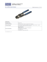
Connecting the BGM (Background Music)
Backgound music can be supplied to the paging system by connecting an audio source such as a mobile phone, tablet etc.
to the 3.5mm input jack on the rear of the paging microphone. Figure 7 shows the position of this connector.
To activate the background music, rst make sure the Push to Talk (PTT) switch is in the centre position and then select
the zones to receive the background music. The selected zones led indicators will ash to signify they have been selected.
Next move the PTT switch to the up position which is lablelled “Lock On”. While the switch is in this position and only this
position will the background music will be piped out to the zones selected.
The volume is adjusted by the BGM volume trimpot on the rear of the microphone.
If the PTT switch is moved to the “Page” position the background music will stop and paging will be active.
If the PTT switch is in the centre position the BGM and paging are not active.
If background music is required again to the same zones as previously selected, then all thats needed to initiate it again is
to move the PTT switch back to the “Lock On” position.
If the BGM is to be piped to different zones then it is only a matter of selecting the new zones, and then moving the PTT
switch to the “Lock On” position.
TO ACTIVATE THE BGM
MOVE THE SWITCH TO
THE “LOCK ON” POSITION
24VDC In
Volume
Mic
Chime
Volume
1 2 3 4
1
2
PA System Chime On
SW
PA System Chime O
Internal Chime On Internal Chime O
On
O
DIP Switches 1-2 Settings
ON
1 2 3 4
BGM
Volume
BGM
Input
REAR OF A 4488
ADJUST THE BACKGROUND
MUSIC VOLUME
BACKGROUND
MUSIC SOURCE
Connecting an audio source to the BGM input
4 Zone Communicator
System Busy
Page
Lock On
All Call Cancel
A 4488
Fig 7

www.altronics.com.au Redback® Proudly Made In Australia
7
Understanding the BGM (Background Music) and Paging Relationship with multiple paging consoles
The background music source is connected to the rear of the paging console as shown in Fig 7. If two paging consoles
are in use, a background music source could be connected to either console, operating on a First In, First serve basis. But
Altronics does not recommended using more than one BGM input.
Unfortunately when the BGM is active on one paging console there is no visual indication of this fact on the other
console. So having two BGM sources would become confusing.
When the BGM is active on Paging console 1 it can be over-ridden by general paging on Paging console 2 and vise versa.
If BGM is active on paging console 1 and paging is to be initiated by this same console then the PTT switch will need to be
moved to the “Page” position. Once the PTT switch is moved off the “Lock On” position, then the BGM stops.
Fig 8a and 8b illustrate a typical example of BGM on one console and paging on the other console.
In Fig 8a paging console 1 has zones 1 & 2 selected and the PTT switch moved to the “Lock On” position. Background
music is being fed to zones 1 & 2. The LED’s on zones 1 & 2 are illuminated indicating which zones have background
music. Paging console 2 has the PTT switch in the OFF position which means its not active and has no visual indication that
the BGM is active to zones 1 & 2.
In Fig 8b Paging console 2 has the PTT switch in the “Page” position and zones 3 and 4 are now active for paging.
Paging console 1 still has the PTT switch in the “Lock On” position. The LED’s on zones 1 & 2 stay illuminated indicating
which zones have background music. But since console 2 is now paging, console 1 has been over-ridden and the paging
audio is now sent to zones 3 & 4. The system busy led is illuminated on console 1 indicating the system is busy and that
console 1 has now been “Locked Out” until console 2 nishes paging. The background music has been disconnected.
Once console 2 nishes paging the BGM will be re-stored to zones 1 and 2.
Paging console 1 has zones 1 & 2
selected and the PTT switch
moved to the “Lock On” position.
Background music is fed to zones 1 &2.
The LED’s on zones 1 &2 are illuminated
indicating which zones have
background music.
4 Zone Communicator
System Busy
Page
Lock On
All Call Cancel
A 4488
4 Zone Communicator
System Busy
Page
Lock On
All Call Cancel
A 4488
Paging console 2 has the
PTT switch in the OFF position
and has no visual indication that
the BGM is active to zones 1 & 2.
Paging Console 1 Paging Console 2
Fig 8a
Paging console 1 still has
the PTT switch in the “Lock On” position.
The LED’s on zones 1 & 2 stay illuminated
indicating which zones have background
music. But since console 2 is paging the
system busy led is illuminated and the
background music has been disconnected.
4 Zone Communicator
System Busy
Page
Lock On
All Call Cancel
A 4488
4 Zone Communicator
System Busy
Page
Lock On
All Call Cancel
A 4488
Paging console 2 has the
PTT switch in the “Page” position
and zones 3 and 4 are active.
Console 1 has now been over-ridden
and the paging audio is now sent
to zones 3 & 4.
Paging Console 1 Paging Console 2
Fig 8b

www.altronics.com.auRedback® Proudly Made In Australia
8
Paging Console
SPECIFICATIONS
OUTPUT MIC LEVEL:......................................................3mV
OUTPUT LINE LEVEL:.........................................................1V
BGM INPUT SENSITIVITY:...........................................500mV
OUTPUT CONNECTORS:
Audio Outputs: (A 4489).............Euroblock terminal
Paging Console (A 4488):....................... RJ45 8P8C
INPUT CONNECTORS:
Line Out Box Input:................................. RJ45 8P8C
24V DC Power (A 4489):..2.1mm JACK (centre +ve)
24V DC Power (A 4488):..2.1mm JACK (centre +ve)
CONTROLS:
Mic Volume:.........................................Rear Volume
Chime Volume:.....................................Rear Volume
BGM Volume:.......................................Rear Volume
POWER SUPPLY:......................................24V DC @ 1 Amp
DIMENSIONS:≈..................... A 4488 - 117W x 135D x 350H
DIMENSIONS:≈.......................A 4489 - 210W x 122D x 44H
WEIGHT: ≈....................................................A 4488 - 0.7 kg
Trouble shooting
SYMPTOMS REMEDIES
Paging consoles not responding
No audio out of A 4489
No audio from zone terminals on
rear of A 4489
No Background music
No Pre-announcement chime
No sound from Microphone
Make sure the ID’s are set correctly
Check Cat5e lead wired correctly
Check wiring to “Audio In” terminals
Check lead on BGM input of paging console
Check BGM volume
Check DIP switch settings
Check chime volume
Check Mic Volume
RJ45 cabling conguration (586A ‘Straight through’)
System components are connected using “pin to pin” conguration RJ45 data cabling as shown in g 9. When installing
ensure all connections are veried with a LAN cable tester before switching any system component on.
Failure to follow the correct wiring conguration may result in damage to system components.
and will Void the warranty.
586A
1 TX+
2 TX-
3 RX +
4
5
6 RX-
7
8
Straight Through
(both ends)
Pins Face Upwards
1 TX+
2 TX-
3 RX +
4
5
6 RX-
7
8
Fig 9
/