Page is loading ...

BL1564
Page 1
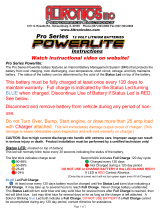
The A 2067 is a line monitoring unit or
LMU. An LMU monitors the condition of
100V PA speaker lines and alerts you if
there is a problem with the wiring.
The A 2067 comes standard with five sepa-
rate zones that have individual LEDs to
indicate the condition of the Line.
The A 2067 can be expanded up to 10
zones when the A 2068 (5 zone card) is
installed.
Features
• Up to 10 zones monitored (with A 2068
installed)
• LED’s to indicate condition of the Line
• Loud alert sound if there is a fault
• Separate rear outputs for the condition
LED’s (via DB26 Socket)
Fitting the A 2068 5 Zone Card
First remove the lid by way of the 6
screws on the top. Then remove the front
panel there are 3 screws on the bottom /
front. Watch for the wire connecting the
switch in the front panel to the pcb. DO
NOT disconnect these wires. Once the lid
and front panel have been removed install
the A 2068 on the four plastic standoffs
already in the chassis. Make sure you
remove the plugable terminal blocks on
the rear of the A 2068 before installation
otherwise it will not fit. Connect the spare
16 Way IDC plug into the A 2068 (Refer to
additional instructions inside case). Screw
the front panel then the lid back into place.
The A 2067 LMU is now ready to be
installed.
Installing the A 2067 LMU
The A 2067 can be powered by a 16VAC
plugpack or 24VDC. Terminals on the rear
are supplied for both.
Hook up the 100V PA amplifier/s to the
inputs on the rear. All the inputs are isolat-
ed from each other so up to 5 amplifiers
(10 if A 2068 fitted) can be used or any
combination below that number e.g. one
amplifier connected to 2 or more inputs.
NEVER
connect 2 or more amplifiers to
one zone it will cause major damage to the
A 2067 and the amplifiers.
The output terminals can now be con-
nected to the speaker lines. A maximum of
100 Watts of load per zone is allowed. Any
more than this will damage the A 2067.
Any number of 100V line transformer /
speaker combinations can be used as long
as the total load for each zone is below 100
Watts.
Setting up the speaker runs so they work
with the A 2067 is as easy as installing a
22uf BP capacitor at the input of each
transformer / speaker (please see figure 3).
Install an end of line resistor or EOL at the
very end of the wiring run before the final
transformer / speaker. The end of line
resistor must be 100K Ohm in value and at
least .25 Watt or above. Unused outputs
from the A 2067 need to have a EOL resis-
tor installed across positive and negative
terminals. If these are not installed the
A 2067 will bring up a fault condition for
the non EOL terminated zones.
Powering up the A 2067
When the A 2067 is powered up the unit
will emit three loud beeps to indicate that
the unit has turned on. The A 2067 then
pauses for about 10 seconds to allow the
protected zones to be checked for the con-
dition they are in.
The unit will then beep once to indicate
that it has checked the zones. If there is a
fault the A 2067 with alert you with a loud
pulsing beep. A short on a zone is indicat-
ed on the front panel by a red LED. An
open condition on a zone will be indicated
on the front panel by a yellow LED. If
there are no faults detected, all zones will
indicate good condition with a green LED.
If the A 2067 goes into alert mode and
the beeping is heard it can be stopped by
pushing the CANCEL button. The fault
LED indicators will remain on until the
fault on the zone is corrected. Any new
fault conditions will result in the alert tone
sounding again.
From then on no matter how many times
the cancel button is pushed the A 2067 will
go into alert mode any time there is a new
fault condition on any of the zones. The
alert will not sound again if a zone goes
from a fault (open or short) condition to
good condition.
Fault Finding
The A 2067 does not power up: Check that
power is applied to the unit either by a
16VAC plugpack or an external 24VDC
source.
Unit continues to go into alert mode and
emits a loud continuous beep: Push the cancel
button and check the LED display. See
which zone is causing the problem (if all
zones are showing “good” the buzzer will
not sound continuously).
The SHORT LED is coming up on a zone:
First check and see if you have installed
the 100K EOL resistor at the end of the line
and the 22uf BP capacitors on each of the
transformer / speakers that are installed
on that line (see diagram). If they are all
installed there must be a short across the
line, once removed the A 2067 will go into
GOOD.
The OPEN LED is coming up on a zone:
First check and see if you have installed
the 100K EOL Resistor at the end of the
line and the 22uf BP Capacitors on each of
the transformer / speakers that are
installed on that line (see diagram). If they
are all installed there must be a break in
the line, once this is removed the A 2067
will go into GOOD.
®
www.altronics.com.au
A 2067 Line
Monitoring Unit
Distributed by Altronic Distributors Pty. Ltd. Perth. Western Australia.
Phone: 1300 780 999 Fax: 1300 790 999
Internet: www.altronics.com.au

Redback A 2067 Line Monitoring Unit
Page 2
BL1564
Remote Fault Monitor
Refer to Instructions for Connections
1
6
V
A
C
Inp
u
t
2
4
V
D
C
In
p
u
t
+
-
Made In Australia by Altronic Distributors Pty Ltd
O
u
t
1
0
In
1
0
O
u
t
9
In
9
O
u
t
8
In
8
O
u
t
7
In
7
O
u
t
6
In
6
In
5
O
u
t
4
In
4
O
u
t
3
In
3
O
u
t
2
In
2
O
u
t
1
In
1
O
u
t
5
-
+
-
+
-
+
-
+
-
+
-
+
-
+
-
+
-
+
-
+
-
+
-
+
-
+
-
+
-
+
-
+
-
+
-
+
-
+
-
+
Zone 1
Zone 2
Zone 3
Zone 4
Zone 5
Zone 6
Zone 7
Zone 8
Zone 9
Zone 10
O
pen
Short
Good
Open
Short
G
ood
Cancel
O
n
Pow
er
REDBACK
A
2
0
6
7
L
in
e
M
o
n
ito
rin
g
U
n
it
5
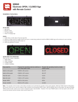
Fig 1. Rear Panel Legend
1 16V AC Input
2 24V DC Input
3 Remote fault connector (DB25)
4 Card 2 (Zones 6 - 10)
5 Card 1 (Zones 1 - 5)
Figure 1: A 2067 rear panel
4
321
Fig 2. Front Panel Legend
1 Zone Indicators 1-10
2 Piezo Buzzer
3 Cancel Button
4 Power Led
5 Power Switch
1
2 3 4 5
Figure 2: A 2067 front panel
Remote Fault Monitoring
A DB25 connector is provided to remote monitor line conditions.
These pins when in “good” condition are 12V. Once a circuit
becomes “open”or “short” the voltage switches to 0V or ground
Pin Number Function
1 Open Zone 10
2 Open Zone 9
3 Open Zone 8
4 Open Zone 7
5 Open Zone 6
6 Open Zone 5
7 Open Zone 4
8 Open Zone 3
9 Open Zone 2
10 Open Zone 1
11 +12V
12 Ground
Pin Number Function
13 Ground
14 Short Zone 10
15 Short Zone 9
16 Short Zone 8
17 Short Zone 7
18 Short Zone 6
19 Short Zone 5
20 Short Zone 4
21 Short Zone 3
22 Short Zone 2
23 Short Zone 1
24 +12V
25 Ground
Out
+
In
+
+
-
+
-
+
-
Fig. 3 Connection Details
Max Load, 100W per zone. Unused zones must have 100k 0.25W
end of line resistor installed. Max wire run, 200m.
Amplifier
22uf capacitors
100K 0.25W end
of line resistor.
Pin
1
2
3
4
5
6
7
8
9
10
14
15
16
17
18
19
20
21
22
23
+ve
Pin 11,24
Pins 12, 13 and 25 are ground
Zone
10
9
8
7
6
5
4
3
2
1
10
9
8
7
6
5
4
3
2
1
Open Circuit
Contacts
Short Circuit
Contacts
Fig. 4 Common Fault Detection
If required the unit can be set up to trigger a relay contact whenever
ANY zone fault occurs eg, Whenever any zone from 1-10 becomes
OPEN or SHORT. Further problem diagnosis can then be determined
from the front panel as required.
/