Page is loading ...

Instruction
Manual
Reaction Torque
Sensor
Type 4507A… and
Type 4509A…
450xA_002-843e-09.23

Foreword
450xA_002-843e-09.23 Page 1
Foreword
This manual applies to the Reaction Torque Sensor Type
4507A… (0150) und Type 4509A… (0154).
The instruction manual must be kept on hand for future
use, and must be available at the site of implementation
of the NC joining system, as needed.
The specifications in this manual can change at any time
without prior notification. Kistler reserves the right to
improve and to change the product for the purpose of
technical progress without the obligation to inform
persons and organizations as the result of such changes.
Original language of these operating instructions:
German
© 2009 … 2023 Kistler Group. All rights reserved.
Kistler Group
Eulachstrasse 22
8408 Winterthur
Switzerland
Phone +41 52-224 11 11
info@kistler.com
www.kistler.com

Reaction Torque Sensor Type 4507A… and Type 4509A…
Page 2 450xA_002-843e-09.23
Content
1. Introduction .................................................................................................................................. 3
2. Important information ................................................................................................................. 4
2.1 Disposal instructions for electrical and electronic equipment ............................................. 4
3. General ......................................................................................................................................... 5
4. Description of the measuring device ........................................................................................ 6
4.1 Mechanical design .............................................................................................................. 6
4.2 Electrical design .................................................................................................................. 7
4.3 Features of the strain gage bridge ...................................................................................... 7
5. Installation .................................................................................................................................... 8
5.1 Electrical connection ........................................................................................................... 8
5.1.1 Troubleshooting ...................................................................................................... 8
5.1.2 Connection assignment .......................................................................................... 8
5.2 Mechanical installation ........................................................................................................ 9
5.2.1 Order of insertion of the measuring device ............................................................ 9
5.3 Examples for the installation of the reaction torque sensor .............................................. 10
5.3.1 Reaction torque sensor with center bore-hole and flanged motor ....................... 10
5.3.2 Reaction torque sensor without center bore-hole with flanged motor .................. 10
5.4 Application example for reactional torque sensor with adapter flange for standard square
drive ................................................................................................................................... 11
6. Calibration .................................................................................................................................. 12
6.1 Electrical calibration .......................................................................................................... 12
6.2 Mechanical calibration ....................................................................................................... 12
6.2.1 Construction of a simple calibration device .......................................................... 12
6.2.2 Example for the calculation of lever arm length ................................................... 13
7. Technical data torque sensor Type 4507A… .......................................................................... 14
8. Technical data torque sensor Type 4509A… .......................................................................... 16
9. Accessories and ordering key ................................................................................................. 18
10. Index ........................................................................................................................................... 19
Total pages 19

Introduction
450xA_002-843e-09.23 Page 3
1. Introduction
Please take the time to thoroughly read this instruction
manual. It will help you with the installation, maintenance,
and use of this product.
To the extent permitted by law Kistler does not accept
any liability if this instruction manual is not followed or
products other than those listed under Accessories are
used.
Kistler offers a wide range of products for use in
measuring technology:
Piezoelectric sensors for measuring force, torque, strain,
pressure, acceleration, shock, vibration and acoustic-
emission
Strain gage sensor systems for measuring force and
torque
Piezoresistive pressure sensors and transmitters
Signal conditioners, indicators and calibrators
Electronic control and monitoring systems as well as
software for specific measurement applications
Data transmission modules (telemetry)
Electromechanical NC joining modules and force-
displacement monitors
Test bed systems for electric motors and gear units for
laboratory, manufacturing, and quality assurance
Kistler also develops and produces measuring solutions
for the application fields engines, vehicles, manufac-
turing, plastics and biomechanics sectors.
Our product and application brochures will provide you
with an overview of our product range. Detailed data
sheets are available for almost all products.
If you need additional help beyond what can be found
either online or in this manual, please contact Kistler's
extensive support organization.

Reaction Torque Sensor Type 4507A… and Type 4509A…
Page 4 450xA_002-843e-09.23
2. Important information
2.1 Disposal instructions for electrical and electronic equipment
Do not discard old electronic instruments in municipal
trash. For disposal at end of life, please return this
product to an authorized local electronic waste dis-
posal service or contact the nearest Kistler Instrument
sales office for return instructions.

General
450xA_002-843e-09.23 Page 5
3. General
Torque sensor with strain gages
Measurement of static and quasi static torques
Mechanical design, protective class IP45
Torque measurement in agitators and other rotating
machine elements
Quality inspection of screw drivers or wrenches
The construction was optimized concerning the length,
weight (moment of inertia) and volume, to minimize axial
forces and bending load on the measuring element.
Through connection of a DC voltage at the strain gage
bridge takes place the transformation of the mechanical
torque into electrical voltage, with standardised output
signal, therefore it is not necessary to do a calibration of
the measuring chain after exchange of the sensor.

Reaction Torque Sensor Type 4507A… and Type 4509A…
Page 6 450xA_002-843e-09.23
4. Description of the measuring device
4.1 Mechanical design
The torque sensor consists of a housing (shaft or flange)
with integrated torsional section with a strain gage full
bridge. The bridge connectors are routed to a built-in
connector or a solid connection cable with 6 pole
connector (depends on the sensor size).
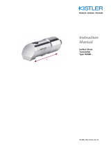
Fig. 1: Mechanical design Reaction Torque Sensor
Type 4507A... and Type 4509A…
Build-in connector
or solid connection cable
with connector
Cable length 2,5 m
with 6 pole connector male
Torsion shaft with
strain gages
Torque sensor
Flange version Type 4507A…
Torque sensor
Shaft end version Type 4509A…
Shaft
Flange
Terminal box
with electronics
Housing

Description of the measuring device
450xA_002-843e-09.23 Page 7
4.2 Electrical design
Fig. 2: Electrical design
R 1 … R 4 strain gages on torsion section surface
ε mechanical strain at connected torque
UB bridge supply voltage
UA measuring signal
4.3 Features of the strain gage bridge
Measuring signal proportional to the torque
High accuracy
Small influence of the bending tension potential on the
measuring signal (mechanical limits must be taken into
account)
Small influence of temperature fluctuation on the
measuring signa
U
B
Supply voltage
Calibration signal (100%
output signal by bridge to
supply -UB (Pin 1)
R 1
R 2
R 4
-ε
R 3
-ε
ε
ε
–
+
–
+
U
A
Measuring
signal
1
2
5
4
6
Connector type
6 pole Binder

Reaction Torque Sensor Type 4507A… and Type 4509A…
Page 8 450xA_002-843e-09.23
5. Installation
5.1 Electrical connection
Use a screened cable with 0,14 mm2 rated cross-section
Factory calibration is performed with 5 m cable length
Change of cable length results in approx. 0,07 % error
per meter
5.1.1 Troubleshooting
Increased cable length: recalibrate the sensor
Installation of the measuring cable: not parallel to heavy
current or control leads; not in the vicinity of transformers,
welding devices, relays, motors
6 pole plug: contact arrangement according to DIN 45322
Abduct away the connection cable from the sensor with a
swan-neck. Otherwise errors may occur by torque shunt.
Transmission of torque as possible close to the flange to
keep bending moments low.
5.1.2 Connection assignment
Built-in connector
Binder Series 680 Type 09-0123-00-06 (6 poles) or
similar
Contact order according to DIN 45322
Mating connector 6 pole female connector (Binder Type:
00-2022.09-6), article no.: 822
Function
Pin
–
Bridge voltage U
1
+
Bridge voltage U
2
Shield
3
+
Measuring signal
4
–
Measuring signal
5
Calibration signal
6

Installation
450xA_002-843e-09.23 Page 9
5.2 Mechanical installation
5.2.1 Order of insertion of the measuring device
Mounting of the adapter flange or other unit and tighten
the screws. Thereby clamp against the adapter flange or
other unit.
Mounting of the sensor to the basic set-up and tighten the
screws.
This will prevent the effects of excessive torque on the
torque sensor during assembly works.
Fig. 3: Torque sensor Type 4507A… with adapter
flange for standard female square drive.
The flanges of motor and basic setup must show a
planned tolerance of 0,01 mm and a surface quality of
Rz4 in order to prevent tightening of the flanges. In case
wider tolerances are used, zero point deviations, which
may change during the operation of the unit and therefore
cause measuring errors, must be taken into account
when tightening the screws.
The maximally allowed cross- and axial forces must be
noted.
When using a transmission after the motor please note
that there are torque shunts in the transmission. For this
reason as shown in the examples, motor and
transmission must always be flanged together at the
sensor.
Protect sensor and motor against any access by persons.
Large bending moments will arise, if someone holds on
the motor. This may result in measuring errors.
Do not assemble any other mechanical parts to the
motor, since this may change the measuring
characteristics of the torque sensor.
Tighten first
Tighten last
Attention to
good flatness

Reaction Torque Sensor Type 4507A… and Type 4509A…
Page 10 450xA_002-843e-09.23
5.3 Examples for the installation of the reaction torque sensor
5.3.1 Reaction torque sensor with center bore-hole and flanged motor
5.3.2 Reaction torque sensor without center bore-hole with flanged motor
Torque sensor Type 4507A… with flanges on booth sides
is qualified for recording reaction torques smooth and
maintenance free. The above examples are especially
recommended to measure torques in agitators.
Rotating drive shaft
Rotating drive shaft
Flange
Torsion section
Motor with transmission
Flange
Motor with transmission
Torsion section

Installation
450xA_002-843e-09.23 Page 11
5.4 Application example for reactional torque sensor with adapter
flange for standard square drive
Fig. 4: Application example for reactional torque sen-
sor with adapter flange for standard square
drive
It will be possible to provide the torque sensor type Type
4507A… with an adapter flange with female square drive.
For this reason the sensor is especially suited to check
up screw drivers and wrenches.

Reaction Torque Sensor Type 4507A… and Type 4509A…
Page 12 450xA_002-843e-09.23
6. Calibration
6.1 Electrical calibration
Attachment of - supply voltage on pin 6 (at 6-pole
connector). The calibration signal effects a measuring
signal at the output which corresponds with the positive
rated torque.
Measuring cable length is not considered.
6.2 Mechanical calibration
This requires a calibration device with lever arm and
weights for torque generation.
Calibration steps:
Adjust precisely the zero point
Load sensor with known torque (e.g. lever arm with
weights)
Adjust display to corresponding torque
6.2.1 Construction of a simple calibration device
Fig. 5: Construction of a simple calibration device
Shiftable half couplings
Lever arm
Torque sensor
Lever arm
bearing
Counter
holding device
Lever arm
Bearing for lever arm
(double)
Weight
(calibrated)

Calibration
450xA_002-843e-09.23 Page 13
6.2.2 Example for the calculation of lever arm length
gm
M
L⋅
=
, wobei
M = torque
L = required lever arm length
M = required mass
G = 9.80665 m/s²
(= normal case acceleration, dependent on location)
Fig. 6: Example for the calculation of lever arm length
Example: m = 1 kg
Mt = 10 N·m
L = = 1,0197 m
m
Mt
L
10 N·m s2
1 kg x 9,80665 m

Reaction Torque Sensor Type 4507A… and Type 4509A…
Page 14 450xA_002-843e-09.23
7. Technical data torque sensor Type 4507A…
Rated output
mV/V
1
Strain gage bridge resistance
350 , Full bridge
Supply voltage
VDC
5 .. 12, to 50 Nm 6V supply
Non-linearity including hysteresis
% FSO
± 0.2
Temperature influence
on the zero point
%/10K
± 0.1
Temperature influence
on the nominal value
%/10K
± 0.1
Nominal temperature range
°C
-5 ... +45
Operating temperature range
°C
-15 ... +55
Relative standard deviation of
repeatability
% FSO
± 0.01
Overload capacity
%
150 of nominal range
Rupture torque
%
>300 of nominal range
Dynamic resilience
%
70 of capacity
Protection class
IP 45
Cable length 2,5 m
10 … 200 N
•
m
500 … 1 000 N
•
m
2 000 … 10 000 N
•
m

Technical data torque sensor Type 4507A…
450xA_002-843e-09.23 Page 15
Measuring range
Nominal torque in
N•m
Dimensions (mm)
Numbers
of holes
of T
Part
Tightening torque
For mounting
N
•
m
L Ø D F Ø A Ø T G
0 ... ±10 N•m
65
70
12
20H7
58
M 8
6 x 60°
16594
1,5
0 ... ±25 N
•
m
65
70
12
20H7
58
M 8
6 x 60°
17445
3
0 ... ±50 N•m
65
70
12
20H7
58
M 8
6 x 60°
17446
6
0 ... ±100 N
•
m
65
70
12
20H7
58
M 8
6 x 60°
17447
12
0 ... ±200 N•m
65
70
12
20H7
58
M 8
6 x 60°
17448
20
0 ... ±500 N
•
m
80
100
15
40H7
82
M 10
8 x 45°
17451
35
0 ... ±1 000 N•m
80
100
15
40H7
82
M 10
8 x 45°
17452
70
0 ... ±2 000 N•m
110
150
20
70g6
120
M 12
6 x 60°
21054
110
0 ... ±5 000 N•m
140
250
25
100g6
220
M 12
8 x 45°
21055
150
0 ... ±10 000 N
•
m
180
280
35
180g6
240
M 18
8 x 45°
21481
250
>10 000 N•m
On request
Mating plug: 6 pole female-connector (Binder type: 99-
2022.09-6), article no.: 822

Reaction Torque Sensor Type 4507A… and Type 4509A…
Page 16 450xA_002-843e-09.23
8. Technical data torque sensor Type 4509A…
Rated output
mV/V
1, 0.5 at 0.25 N·m
Strain gage bridge resistance
350, Full bridge
Supply voltage
N·m
5 to 6 V, >5 to 12 V
Non-linearity including hysteresis
% FSO
±0,2
±0.3 for measure
range 0.5 N·m and 0.25 N·m
Relative standard deviation of repeatability
% FSO
± 0.02
Temperature influence on the zero point
%/10 K
± 0.1
Temperature influence on the nominal value
%/10 K
± 0.1
Nominal temperature range
°C
-5 ... +45
Operating temperature range
°C
-15 ... +55
Overload capacity
%
150 of the nominal torque
Rupture torque
%
>300 of the nominal torque
Dynamic resilience
%
70 from nominal torque
Protection class
IP 45
cabel length 2,5 m
with 6 pole-connector male
Nominal torque 0,5 … 20 N
•
m
Nominal torque 50 und 100 N
•
m
6 pole connector male

Technical data torque sensor Type 4509A…
450xA_002-843e-09.23 Page 17
Measuring
range
Nominal torque
in N•m
Dimensions (mm)
Feather
key slots Part
L Ø D1 Ø D2 B
0,5
50
38 12 12 without 6034
1
50
38 12 12 without 6033
2
50
38 12 12 without 5648
5
50
38 12 12 2x180° 5653
10
50
38 12 12 2x180° 5794
20
50
38 12 12 2x180° 5784
50
100
45 18 30 2x180° 21524
100
100
45 18 30 2x180° 17277
* Both shaft ends with feather key slots(2x 180°) acc. to
DIN 6885, sheet 1

Reaction Torque Sensor Type 4507A… and Type 4509A…
Page 18 450xA_002-843e-09.23
9. Accessories and ordering key

Index
450xA_002-843e-09.23 Seite 19
10. Index
A
Accessories and ordering key .................. .... 16
Application example for reactional
torque sensor............................................ .... 11
C
Calibration ................................................ .... 12
Connection assignment ............................ ...... 8
Construction of a simple calibration device ... 12
D
Description of the measuring system ....... ...... 6
Disposal Instructions ................................ ...... 4
E
Electrical calibration ................................. .... 12
Electrical connection ................................ ...... 8
Electrical design ....................................... ...... 7
Example for the calculation of lever
arm length ................................................. .... 13
Examples for the Installation .................... .... 10
F
Features of the strain gage bridge ........... ...... 7
G
General ..................................................... ...... 5
H
Help ........................................................... ..... 3
I
Important information ................................ ..... 4
Installation ................................................. ..... 8
Introduction ............................................... ..... 3
M
Mechanical calibration .............................. ... 12
Mechanical design .................................... ..... 6
Mechanical installation .............................. ..... 9
O
Order of insertion of the measuring device ..... 9
R
Reaction torque sensor with center
bore-hole and flanged motor..................... ... 10
Reaction torque sensor without center
bore-hole with flanged motor .................... ... 10
T
Technical data torque sensor Type 4507A… 14
Technical data torque sensor Type 4509A… 15
Troubleshooting ........................................ ..... 8
/