Page is loading ...

Tel. +41 52 224 11 11
info@kistler.com
www.kistler.com
Kistler Group
Eulachstrasse 22
8408 Winterthur, Switzerland
ENG
Introduction
The information stated in this document may be changed
at any time without a prior announcement. Kistler reserves
the right to improve and modify the product in keeping with
technical advances, with no obligation to notify individuals
or organizations on account of such changes.
Insofar as permitted by law, Kistler declines all liability in
case of actions contrary to these QuickStart instructions,
or if accessory is used, that is not listed in the datasheet or
communicated by Kistler
© 2020 ... 2022 Kistler Group. All rights reserved. Products
of the Kistler Group are protected by various intellectual
property rights. For more information, visit: www.kistler.com.
General information
• Do not open the amplifier (danger and loss of warranty)
• Commissioning by specialist staff only
• Comply with product-specific and nationally applicable
safety provisions
• Only perform manipulations with power off (dead)
Do not use devices that have been damaged, manipulated
or stored incorrectly; send them to Kistler Instrumente AG
or its representatives for repair.
Keep the plug connections dry and free of dust. When not
in use, cover with the protective caps supplied.
Firmware Updates
This device does allow Firmware update by customer, using
any standard IO-Link tool with Firmware update function-
ality. The latest Firmware Version is listed on the product
website at www.kistler.com. Please feel free to get in contact
with your Kistler Service Center in order to check options
to update your device to the latest Firmware.
Dimensions
18,5
31,4
5
24,65
SN_ _ _ _ _ _
5028A _ _ _
Output:
Plug M12x1, 4 pole
Input:
Kiag 10-32UNF
25
38
3 32
19 3
12
29,5
10,75
13
R3,5
4
Measure
Sensor
Power/Out
5028A
Link
Mini Industrie-LV mit IO-Link
Cadenas 5028A_
A4
0
1 / 1
1.5:1
measure. analyze. innovate.
Erstmals verwendet
Erste Proj.-Nr.
Werkstoff
Änderung
Datum
Massstab
Ersatz für
Kopie Datum
08.11.2019
gez.
gepr.
ges.
08.11.2019
Wls
100.429.652
Zeichnungs-Nr.
Material-Nr.
KIWAG-SWX_A4h / Vers. 21-Sep-2017
Ver.
Bl.
5028A_
D-00259-C1
siehe Tabelle
öffentlich
Das Urheberrecht an dieser Zeichnung, die dem Empfänger
persönlich anvertraut wird, verbleibt unserer Firma.
Ohne unsere schriftliche Genehmigung darf die Zeichnung
weder kopiert noch vervielfältigt, noch an Drittpersonen
mitgeteilt oder zugänglich gemacht werden.
For mounting, 2x thread M3x20 are required.
EMC and ground loops
At any time, the amplifier must be mounted onto a shielding
or metallic surface to prevent electrical fields from influenc-
ing the signal acquisition.
As sensor connector, amplifier housing and IO-Link Ground
are internally connected, it may be necessary for some
applications to take countermeasures against ground loops.
A low-impedance and at the same time low-inductance
connection between amplifier case, sensor and customer
system (large-area copper braiding, ribbon cable) usually
provides good results.
Kistler provides insulation elements for sensors as well as
ground insulation kits for the 5028A amplifier series. See
instruction manual section “Installation” for details.
LED Indication
LED Indication
Reset: blue blinking 1Hz
Operate: blue
Overload: red
Time constant enabled: green
System connector
1
2
3
4
Operation and configuration
All configuration is done using IO-Link. Please get the IODD
file from https://ioddfinder.io-link.com or from the Kistler
website directly. Type 5028A amplifier will automatically
turn into analog operation mode if no IO-Link Master is
detected during startup.
For operation using the analog voltage output signals, it is
essential to use shielded cables.
Cyclic data
Cyclic data according to IO-Link Specification V1.1 Smart
Sensor Profile SSP4.3.1:
“Measuring and Switching Sensor, floating point, 1 channel”
PD In (Device to Master) bit 48
Process Data Input structure:
Measurement value (Fraction32bit|Exp.8bit|Sign1bit) |
Vendor specific. (8 bit)
Name Data Type Length
(Byte)
Measure-
ment Value
Float32T
(Fraction32bit|Exp.8bit|Sign1bit)
4
Vendor Bitfield 1
Specific 0.
1.
2.
3.
4.
5.
6.
Switch Point 1
Switch Point 2
Operate
Overload
Trigger1
(future option)
Service calibration
(future option)
… 15. Reserved
(Bit0)
(Bit1)
(Bit2)
(Bit3)
(Bit4)
(Bit5)
(Bit6 ... 15)
PD Out (Master to Device) bit 8
Process Data Output structure:
Vendor specific. (bit 1-7) | Disable (bit 0)
Name Data Type Length
(Byte)
Control Bitfield 1
0.
1.
2.
3.
4.
5.
6.
7.
Reset (Disable)
Vendor Specific
Vendor Specific
Vendor Specific
Vendor Specific
Vendor Specific
Vendor Specific
Vendor Specific
(Bit0)
(Bit1)
(Bit2)
(Bit3)
(Bit4)
(Bit5)
(Bit6)
(Bit7)
Page 2
18
© 2013 … 2017 Kistler Group, Eulachstrasse 22, 8408 Winterthur, Switzerland
Tel.
+41
52
224
11 11, Fax
+41
52
224
14 14, [email protected]m, www.kistler.com
Kistler Group products are protected by various intellectual property rights. For
more details visit www.kistler.com.
This information corresponds to the current state of knowledge. Kistler reserves
the right to make technical changes. Liability for consequential damage resulting
from the use of Kistler products is excluded.
Mounting
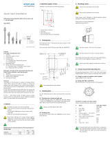
To mount the amplifier, use the diagonal flange and M3x20 Cylinder Head Screws.
LED
Indication
Reset: blue blinking 1Hz
Operate: blue
Overload: red
Pin
Function
1
L+ Power Supply Us, +24V
2
Analog Signal Output +/-10V
3
L- Power Supply GND / Signal GND
4
C/Q IO-Link Communication or digital Input: Operate
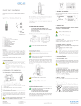
Fig. 1: Dimensions and LED codes
Fig. 2: Dimensions with cables and amplifier pinout
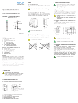
At any time, the amplifier must be mounted onto a shielding surface, in order to cover the bottom side.
Otherwise, electrical fields may influence the signal acquisition part of the amplifier directly.
Fig. 3: Mount to GND: Use shielding EMC pad if required (Accessory)
Fig. 4: Insulate from GND if required (Accessory)
Used electronic equipment must not be disposed
of with household garbage or residual waste.
Please return disused or retired equipment to
the nearest electronic waste collection point for
disposal, or contact your Kistler Sales Center.
https://www.kistler.com/en/product/
type-5028a
Data sheet 5028A (003-477)
Operating instructions 5028A (002-895) EN
QuickStart instructions
mICA – miniature Industrial Charge Amplifier
with IO-Link, Type 5028A
5028A_002-894e-05.22 © 2020 ... 2022 Kistler Group
General data
Operating temperature range °C –20 ... 65
Storage temperature range °C –40 ... 85
Vibration resistance IEC60068 Part 2-6
(58 ... 150 Hz constant)
gp 1
Shock resistance IEC60068 Part 2-27 (11ms) g 200
Degree of protection as per EN60529 (only
with cables fitted and/or covered connectors)
IP 67
Housing material aluminum
passivated
Weight g 30
Power supply
Supply voltage VDC 18 ... 30
Power consumption at 24V mA <50
Overvoltage resistance 40ms/
max
V 55
Galvanic isolation from
measuring circuit and digital
inputs typ. (not safety relevant)
VDC <50
Connectors
Sensor charge input Type KIAG 10-32 UNF neg.
IO-Link/System Type M12x1 4 pole male
Block diagram
Acyclic user and configuration data
Parameter name Parameter Type Default IO-Link Index
User Sensitivity Float (Fraction32bit|Exp.8bit|Sign1bit) byte 4 –1 index:256
User Range Float (Fraction32bit|Exp.8bit|Sign1bit) byte 4 500
5000
50000
100 000
500000
index:257
Switch Point 1 Level Float (Fraction32bit|Exp.8bit|Sign1bit) byte 4 0 index:258
Switch Point 2 Level Float (Fraction32bit|Exp.8bit|Sign1bit) byte 4 – User Range
Default
index:259
Switch Point Mode UIntegerT8 byte 1 0 index:260
Operating Hours (ro) UIntegerT16 byte 2 – index:261
Low-Pass Filter UIntegerT8 byte 1 0 – Deact. index:262
Time Constant UIntegerT8 byte 1 0 – Deact. index:263
Temperature Case Actual (ro) Float (Fraction32bit|Exp.8bit|Sign1bit) byte 4 – index:264
Temperature Case +Max (ro) Float (Fraction32bit|Exp.8bit|Sign1bit) byte 4 – index:265
Temperature Case -Max (ro) Float (Fraction32bit|Exp.8bit|Sign1bit) byte 4 – index:266
Measure High or Low Active UIntegerT8 byte 1 0 index:267
Switch Point Hysteresis Float (Fraction32bit|Exp.8bit|Sign1bit) byte 4 0 index:268
Product Type (ro) Ostring byte 15 – index:269
Calibration Date (ro) Ostring byte 15 – index:270
Units UIntegerT8 byte 1 M.U. index:271
Range Analog Output Float (Fraction32bit|Exp.8bit|Sign1bit) byte 4 10 index:272
Reset to Measure Jump
Correction
UIntegerT8 byte 1 0 – Deact. index:273
Corresponding Output
Voltage (ro)
Float (Fraction32bit|Exp.8bit|Sign1bit) byte 4 – index:274
Technical data
Reduced scope. For complete details, refer to the data sheet or instruction instructions.
/

