Page is loading ...

Crestron TPS-6X-IMCW
Interface Module
Installation Guide

This document was prepared and written by the Technical Documentation department at:
Crestron Electronics, Inc.
15 Volvo Drive
Rockleigh, NJ 07647
1-888-CRESTRON
Regulatory Compliance
Federal Communications Commission (FCC) Compliance Statement
This Class B digital apparatus complies with Canadian ICES-003.
Cet appareil numérique de la classe B est conforme à la norme NMB-003 du Canada.
Industry Canada (IC) Compliance Statement
This device complies with part 15 of the FCC Rules. Operation is subject to the following conditions:
(1) This device may not cause harmful interference and (2) this device must accept any interference received,
including interference that may cause undesired operation.
CAUTION: Changes or modifications not expressly approved by the manufacturer responsible for compliance
could void the user’s authority to operate the equipment.
NOTE: This equipment has been tested and found to comply with the limits for a Class B digital device,
pursuant to part 15 of the FCC Rules. These limits are designed to provide reasonable protection against harmful
interference in a residential installation. This equipment generates, uses and can radiate radio frequency energy
and, if not installed and used in accordance with the instructions, may cause harmful interference to radio
communications. However, there is no guarantee that interference will not occur in a particular installation. If
this equipment does cause harmful interference to radio or television reception, which can be determined by
turning the equipment off and on, the user is encouraged to try to correct the interference by one or more of the
following measures:
Reorient or relocate the receiving antenna
Increase the separation between the equipment and receiver
Connect the equipment into an outlet on a circuit different from that to which the receiver is connected
Consult the dealer or an experienced radio/TV technician for help
As of the date of manufacture, the TPS-6X-IMCW has been tested and found to comply with specifications for
CE marking and standards per EMC and Radiocommunications Compliance Labelling.
All brand names, product names and trademarks are the property of their respective owners.
©2010 Crestron Electronics, Inc.

Crestron TPS-6X-IMCW Interface Module
Contents
Interface Module for TPS-6X-DS: TPS-6X-IMCW 1
Introduction ...............................................................................................................................1
Features and Functions................................................................................................ 1
Specifications ..............................................................................................................2
Physical Description....................................................................................................4
Setup .......................................................................................................................................... 9
Network Wiring........................................................................................................... 9
Supplied Hardware....................................................................................................10
Installation................................................................................................................. 11
Hardware Hookup .....................................................................................................13
Problem Solving ......................................................................................................................16
Troubleshooting......................................................................................................... 16
Check Network Wiring..............................................................................................17
Further Inquiries ........................................................................................................18
Future Updates ..........................................................................................................18
Return and Warranty Policies .................................................................................................. 19
Merchandise Returns / Repair Service ......................................................................19
CRESTRON Limited Warranty.................................................................................19
Installation Guide – DOC. 6874B Contents • i


Crestron TPS-6X-IMCW Interface Module
Interface Module: TPS-6X-IMCW
Introduction
The TPS-6X-IMCW is the interface module that is included as standard
with the Isys™ TPS-6 Tilt Touchpanel, TPS-6X Series Wireless
Touchpanels and TPS-6X-DS and TPS-6XNL-DS Docking Stations. It
provides a convenient pluggable connection for the docking station via a
single 10-pin RJ-50 jack on its front panel. On the rear are connections
for Cresnet
®
, Ethernet, balanced or unbalanced video and a choice of
Cresnet or local DC power. An additional DC power jack is included on
the front panel to simplify the connection of a local power supply in a
typical wall mount application.
Using the hardware provided, the TPS-6X-IMCW can be mounted in a
standard 1-gang electrical box, to a flat surface or to a 19-inch rack rail.
Multiple TPS-6X-IMCW interface modules may be purchased
individually and installed as part of a complete system to provide
multiple connection locations.
Features and Functions
• Single wire connection for the TPS-6, TPS-6X Series and
TPS-6X-DS and TPS-6XNL-DS docking stations
• Mounts in a single-gang wall box
• Includes inserts to match black or white faceplates
• Surface mount and rack rail installation options included
• Wired Ethernet and Cresnet control system connections
• Balanced or coaxial video input
• Versatile powering options
Installation Guide – DOC. 6874B Interface Module: TPS-6X-IMCW • 1

Interface Module Crestron TPS-6X-IMCW
Specifications
Specifications for the TPS-6X-IMCW are listed in the following table.
TPS-6X-IMCW Specifications
SPECIFICATION DETAILS
Power Requirements*
Power Pack 0.75 Amps @ 24 Volts DC
(power pack sold separately)
Cresnet Power Usage 0.5 Watts
(0.02 Amps @ 24 Volts DC),
module only;
18 Watts
(0.75 Amps @ 24 Volts DC),
with TPS-6 or TPS-6X Series
touchpanel connected
Environmental
Temperature 32º to 112ºF (0º to 45ºC)
Humidity 10% to 90% RH
(non-condensing)
Heat Dissipation 61 BTU/Hr
Enclosure
Construction Metal, black matte powder coat
finish, includes (2) metal inserts
to allow choice of black or white
front panel
Flush Wall Mount 1-gang mountable in a standard
electrical box, 2.5 inch (64 mm)
deep minimum; requires third-
party decorative faceplate (not
included)
Surface Mount Surface mount bracket included
Rack Mount Mountable to a single 19-inch EIA
rack rail
(Continued on following page)
2 • Interface Module: TPS-6X-IMCW Installation Guide – DOC. 6874B

Crestron TPS-6X-IMCW Interface Module
TPS-6X-IMCW Specifications (Continued)
SPECIFICATION DETAILS
Dimensions
Height 4.11 in (105 mm)
Width 1.72 in (44 mm)
1.93 in (49 mm) with surface
mount bracket
Depth 1.43 in (37 mm)
1.49 in (38 mm) with surface
mount bracket
Weight 6 oz (162 g)
9 oz (232 g) with bracket
Available Accessories
Power Pack 24 Volt Power Pack, Universal
* May be powered by power pack (sold separately) or Cresnet network power, not
both.
Installation Guide – DOC. 6874B Interface Module: TPS-6X-IMCW • 3

Interface Module Crestron TPS-6X-IMCW
Physical Description
This section provides information on the connections, controls and
indicators available on your TPS-6X-IMCW.
TPS-6X-IMCW Physical View
4 • Interface Module: TPS-6X-IMCW Installation Guide – DOC. 6874B

Crestron TPS-6X-IMCW Interface Module
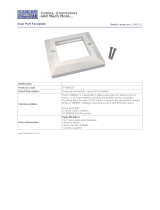
TPS-6X-IMCW Overall Dimensions
1.67 in
(43 mm)
3
4
5
6
1.72 in
(44 mm)
4.11 in
(105 mm)
1
2
3
1.43 in
(37 mm)
1.24 in
(32 mm)
2.62 in
(67 mm)
5.00 in
(127 mm)
7
Installation Guide – DOC. 6874B Interface Module: TPS-6X-IMCW • 5

Interface Module Crestron TPS-6X-IMCW
Connectors, Controls & Indicators
# CONNECTORS
1
,
CONTROLS &
INDICATORS
DESCRIPTION
1 TO PANEL
(1) 10-wire RJ-50 female;
Connection for TPS-6 touchpanel or
TPS-6X Series docking station
TYPE PIN COLOR SIGNALS
1 Gray Ground
2 Orange/
White
Ethernet
TX+
3 Orange Ethernet
TX-
4 Green/
White
Ethernet
RX+
5 Blue Cresnet Y
6 Blue/
White
Cresnet Z
7 Green Ethernet
RX-
8 Brown/
White
Diff Video
+
9 Brown Diff Video
-
10-Position
RJ-50
10 Gray/
White
Power 24V
2 PWR LED (1) Green LED, indicates DC power
supplied from Cresnet network or DC
power pack
3 PWR
24VDC .75A
2
(1 on front panel and 1 on back
panel) 2.1 mm barrel DC power jack;
24 Volt DC power input;
(power supply sold separately)
(Continued on following page)
6 • Interface Module: TPS-6X-IMCW Installation Guide – DOC. 6874B

Crestron TPS-6X-IMCW Interface Module
Connectors, Controls, & Indicators (Continued)
# CONNECTORS
1
,
CONTROLS &
INDICATORS
DESCRIPTION
4 VIDEO IN
3
-
+
VS
S
BAL
UNBL
(1) 3-pin 3.5 mm detachable
terminal block;
Balanced composite video input;
Input impedance: 100 Ω nominal;
Input level: 1 V
p-p
nominal,
1.5 V
p-p
maximum;
Maximum DC offset: ±2 Volts;
Connects to any Crestron CAT5
video out port via CresCAT cable
(1) 2-pin 3.5 mm detachable
terminal block;
Unbalanced composite video input;
Input impedance: 75 Ω nominal
Input level: 1 V
p-p
nominal,
1.5 V
p-p
maximum;
Maximum DC offset: ±2 Volts;
Connects to any conventional coax
video source
5 NET
2
24
GZY
(1) 4-pin 3.5 mm detachable
terminal block;
Cresnet slave port, connects to
Cresnet control network
24: Power (24 Volts DC)
Y: Data
Z: Data
G: Ground
(Continued on following page)
Installation Guide – DOC. 6874B Interface Module: TPS-6X-IMCW • 7

Interface Module Crestron TPS-6X-IMCW
Connectors, Controls, & Indicators (Continued)
# CONNECTORS
1
,
CONTROLS &
INDICATORS
DESCRIPTION
6 LAN
(1) 8-wire RJ-45;
10/100BASE-T Ethernet port
TYPE PIN SIGNALS
1 TD+
2 TD-
3 RD+
4 N/C
5 N/C
6 RD-
7 N/C
8-Position
RJ-45
8 N/C
7 GROUND
4
(1) Flying lead, grounding wire
1. Interface connectors for NET and VIDEO IN ports are provided with the unit.
2. May be powered by power pack (sold separately) or Cresnet network power, not
both. Be sure to use a Crestron approved power supply as another may cause
damage.
3. Balanced and unbalanced video inputs are mutually exclusive.
4. A grounding lead is provided for connection to earth ground (building steel). This
ground connection is recommended to provide a common ground reference for
signals provided to the TPS6X-IMCW, notably video inputs and to reduce the
incidence of possible damage to the unit from static discharge.
8 • Interface Module: TPS-6X-IMCW Installation Guide – DOC. 6874B

Crestron TPS-6X-IMCW Interface Module
Setup
Network Wiring
When wiring the Cresnet and Ethernet network, consider the following:
• Use Crestron Certified Wire.
• Use Crestron power supplies for Crestron equipment.
• Provide sufficient power to the system.
CAUTION: Insufficient power can lead to unpredictable results
or damage to the equipment. Please use the Crestron Power
Calculator to help calculate how much power is needed for the
system (www.crestron.com/calculators
).
Cresnet
For networks with 20 or more devices, use a Cresnet Hub/Repeater
(CNXHUB) to maintain signal quality.
For more details, refer to “Check Network Wiring” which starts on page
17.
Ethernet
The TPS-6X-IMCW can also use high-speed Ethernet for
communications between the device and a control system, computer,
digital media server and other IP-based devices.
For information on connecting Ethernet devices in a Crestron system,
refer to the latest version of the Crestron e-Control
Reference Guide
(Doc. 6052), which is available from the Crestron website
(www.crestron.com/manuals
).
Installation Guide – DOC. 6874B Interface Module: TPS-6X-IMCW • 9

Interface Module Crestron TPS-6X-IMCW
Supplied Hardware
The hardware supplied with the TPS-6X-IMCW is listed in the following
table.
Supplied Hardware for the TPS-6X-IMCW
DESCRIPTION PART
NUMBER
QTY
Assy, Insert, Black 4503186 1
Assy, Insert, White 4503188 1
Metal, Bracket, 16 GA CRS 2016054 1
Conn, Plug, 2-pin, SKT, Single Row 2003574 1
Conn, Plug, 3-pin, SKT, Single Row 2003575 1
Conn, Plug, 4-pin, SKT, Single Row 2003576 1
Hole Plug, Ferrule Dust Cap, Blk 2017028 1
Screw, #06-32 x 1”, Flat, Slot 2013235 2
Screw, #06-32 x 3/16”, Pan, Phil 2007203 2
10 • Interface Module: TPS-6X-IMCW Installation Guide – DOC. 6874B

Crestron TPS-6X-IMCW Interface Module
Installation
The TPS-6X-IMCW can be installed in either a 1-gang box, rack
mounted or mounted to any flat surface using the provided surface mount
bracket.
Installing in
1-Gang Box
To install the TPS-6X-IMCW in a 1-gang box, ensure the unit is mounted
into the electrical box as shown in the following illustration.
TPS-6X-IMCW 1-Gang Box – Exploded View
1-Gang Wall Box
(Not Supplied)
TPS-6X-IMCW
(6501242)
Screws (2) #6-32 X 1"
(2013235)
Wall Plate With
Hardware
(Not Included)
Assy, Insert, Black
(4503186)
or
Assy, Insert, White
(4503188)
Mounting Surface
Installation Guide – DOC. 6874B Interface Module: TPS-6X-IMCW • 11

Interface Module Crestron TPS-6X-IMCW
Rack
Mounting
The TPS-6X-IMCW can be mounted in a rack with other equipment
using the four mounting holes on the corners of the interface module, as
shown in the following illustration.
TPS-6X-IMCW Rack Mount – Exploded View
Rack Mount Screws
(Not Supplied)
Rack Rail
TPS-6X-IMCW
(6501242)
Assy, Insert, Black
(4503186)
or
Assy, Insert, White
(4503188)
WARNING: To prevent bodily injury when mounting or servicing this
unit in a rack, take special precautions to ensure that the system remains
stable. The following guidelines are provided to ensure your safety:
• When mounting this unit in a partially filled rack, load the rack
from the bottom to the top with the heaviest component at the
bottom of the rack.
• If the rack is provided with stabilizing devices, install the
stabilizers before mounting or servicing the unit in the rack.
12 • Interface Module: TPS-6X-IMCW Installation Guide – DOC. 6874B

Crestron TPS-6X-IMCW Interface Module
Installing on
a Level
Surface
To prepare the TPS-6X-IMCW to be mounted onto a level surface,
ensure the unit is attached to the surface mount bracket, as shown in the
following illustration.
TPS-6X-IMCW Bracket Mount – Exploded View
TPS-6X-IMCW
(6501242)
Mounting Bracket
(2016054)
Screws (2) #6-32 X 3/16"
(2007203)
Assy, Insert, Black
(4503186)
or
Assy, Insert, White
(4503188)
Hardware Hookup
Make the necessary connections as called out in the illustration on the
following page. Refer to “Network Wiring” on page 9 before attaching
the 4-position terminal block connector. Apply power after all
connections have been made.
When making connections to the TPS-6X-IMCW, use Crestron power
supplies for Crestron equipment.
Installation Guide – DOC. 6874B Interface Module: TPS-6X-IMCW • 13

Interface Module Crestron TPS-6X-IMCW
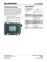
Hardware Connections for the TPS-6X-IMCW (Front)
TO PANEL:
Connect to TPS-6
touchpanel or
TPS-6X Series
docking station via
10-Pin RJ-50 Cable
(Cable Provided
with docking
station)
POWER*:
From DC
Power Pack
* A ferrule dust cap (2017028) is provided to cover the front panel DC power jack
when not in use.
Hardware Connections for the TPS-6X-IMCW (Back)
POWER:
From DC
Power Pack
VIDEO IN:
Balanced or
Unbalanced Source
NET:
To Control System
and Other Cresnet
Devices
LAN:
10/100BASE-T
to LAN
NOTE: Ensure the unit is properly grounded by connecting the chassis
ground lug to an earth ground (building steel).
14 • Interface Module: TPS-6X-IMCW Installation Guide – DOC. 6874B

Crestron TPS-6X-IMCW Interface Module
NOTE: The TPS-6X-IMCW can be powered via the PWR jack on
either the front or the back of the unit if the NET port is not being used to
power the module.
Installation Guide – DOC. 6874B Interface Module: TPS-6X-IMCW • 15

Interface Module Crestron TPS-6X-IMCW
Problem Solving
Troubleshooting
The following table provides corrective action for possible trouble
situations. If further assistance is required, please contact a Crestron
customer service representative.
TPS-6X-IMCW Troubleshooting
TROUBLE POSSIBLE
CAUSE(S)
CORRECTIVE
ACTION
Device is not
receiving
sufficient power.
Use a Crestron
approved power
source and verify
connections.
Device does not
function.
Use the Crestron
Power Calculator to
help calculate how
much power is
needed for the
system.
PWR LED does
not illuminate.
Device is not
receiving
sufficient power.
Use a Crestron
approved power
source and verify
connections.
Use the Crestron
Power Calculator to
help calculate how
much power is
needed for the
system.
Loss of
functionality
due to
electrostatic
discharge.
Improper
grounding.
Check that all ground
connections have
been made properly.
16 • Interface Module: TPS-6X-IMCW Installation Guide – DOC. 6874B
/