
1
Installation, Assembly and Operating Instructions
I.V. ROD TELESCOPING KIT
9000XT RECLINER - KIT NO. 1074656
2000, 4000 AND 9000 RIDELITE
RECLINER - KIT NO. 1029598
NOTE: Check ALL parts for shipping damage. In case of
shipping damage, DO NOT use. Contact Carrier/Dealer
for further instruction.
SAFETY SUMMARY
The following recommendations are made for safe instal-
lation and adjustment of the I.V. Rod Telescoping Kit:
GENERAL WARNINGS
DO NOT install or use this equipment with-
out first reading and understanding this
instruction sheet. If you are unable to un-
derstand the Warnings, Cautions or Instruc-
tions, contact a healthcare professional,
dealer or technical personnel before at-
tempting to install this equipment - other-
wise, injury or damage may occur.
DO NOT pull/push the wheelchair by the
I.V. rod assembly. Injury to the assistant/
occupant and/or damage to the I.V. rod
assembly may occur.
DO NOT place any other objects on the
I.V. rod assembly other than those deter-
mined by a healthcare professional.
INSTALLATION WARNINGS
After ANY adjustments, repair or service
and BEFORE use, make sure all attaching
hardware is securely tightened - other-
wise injury or damage may result.
Use EXTREME caution when the I.V. rod
holder for MODELS 2000, 4000 and 9000
Ridelite is installed. When installed, the rear
arm release lever is removed and will NOT
lock the arm in place.
NOTE: If installing the telescoping I.V. rod holder onto
a 2000, 4000 or 9000 RIDELITE, refer to INSTALL-
ING THE TELESCOPING I.V. ROD HOLDER - 2000,
4000 or 9000 RIDELITE in this instruction sheet.
INSTALLING THE TELESCOPING
I.V. ROD HOLDER - 9000XT ONLY
(FIGURE 1)
NOTE: Refer to INSTALLATION WARNINGS in the
SAFETY SUMMARY in this instruction sheet.
1. Remove the rear wheel from the wheelchair. Refer to
REMOVING/INSTALLING THE REAR WHEELS
in this instruction sheet.
2. Remove the arm from the wheelchair. Refer to RE-
MOVING/INSTALLING THE ARMRESTS in this in-
struction sheet.
3. Remove the locknut and hex screw that secure the
arm socket to the wheelchair frame.
4. Remove the locknut that secures the back tube to the
clevis bracket.
5. Position the I.V. holder on the existing pivot bolt as
shown in FIGURE 1.
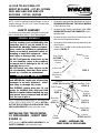
FIGURE 1 - INSTALLING THE
TELESCOPING I.V. ROD HOLDER
Arm Socket
(OUTSIDE of
Wheelchair
Frame)
Locknut
Outside of
Wheelchair
Frame
Locknut
(STEP 8,9,11)
Mounting
Screw
(STEP 7)
I.V. Holder
(STEP 5)
Hex
Screw
STEP 3
Clevis
Bracket
(STEP 4)
Pivot Bolt
(STEP 5)
Back Tube
(STEP 4)
Locknut
(STEPS 4,6,11 )
Flat Portion
(STEP 5)
Front
Cylinder
Side Frame

2
6. Reinstall locknut onto pivot bolt. DO NOT tighten.
7. Install the provided mounting screw through the lower
hole on the front cylinder section of the I.V. holder and
into the side frame.
8. Install locknut onto mounting screw.
9. Turn locknut until snug fit is obtained. DO NOT tighten.
10. Reinstall the arm to ensure proper fit. Refer to RE-
MOVING/INSTALLING THE ARMRESTS in this in-
struction sheet.
11. Securely tighten both locknuts of STEPS 6 AND 9.
12. Install the I. V. rod support tube. Refer to INSTALL-
ING THE I.V. ROD SUPPORT TUBE in this instruc-
tion sheet.
INSTALLING THE I.V. ROD
SUPPORT TUBE (FIGURE 2)
NOTE: Refer to INSTALLATION WARNINGS in the
SAFETY SUMMARY in this instruction sheet.
NOTE: The I.V. holder must already be mounted to the
side frame of the wheelchair.
1. Insert the I.V. rod support tube into the rear cylinder of
the I.V. rod holder.
NOTE: When installing the I.V. rod support tube, ensure
the adjustment knob is pointing out away from the wheel-
chair.
2. Turn the I.V. rod support tube until the holes in the I.V.
rod support tube align with the holes in the rear cylin-
der of the I.V. rod holder.
3. Press the large nylon washer into the back hole of the
rear cylinder so that it is flush with outside surface.
4. Insert mounting screw through rear cylinder, large
nylon washer, small nylon washer, and steel washer.
5. Install locknut onto mounting screw. Securely tighten.
6. Reinstall the rear wheel onto the wheelchair. Refer to
REMOVING/INSTALLING THE REAR WHEELS
in this instruction sheet.
7. Adjust I.V. rod to desired height. Refer to ADJUST-
ING THE I.V. ROD in this instruction sheet.
ADJUSTING THE I.V. ROD
(FIGURE 2)
NOTE: Refer to INSTALLATION WARNINGS in the
SAFETY SUMMARY in this instruction sheet.
1. Loosen adjustment knob.
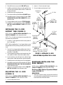
FIGURE 2 - INSTALLING I.V. ROD
SUPPORT TUBE/ADJUSTING THE I.V. ROD
NOTE: Attaching hardware
enlarged 3X scale for clarity.
I.V. Rod
Holder
(STEP 1)
Adjustment
Knob
Steel
Washer
(STEP 4)
Rear
Cylinder
Large
Nylon
Washer
(STEPS 3
AND 4)
Small Nylon
Washer
(STEP 4)
Locknut
(STEP 5)
Mounting Screw
(STEP 4)
I.V. Rod
Support Tube
(STEPS 1,2)
I.V. Rod
REMOVING/INSTALLING THE
REAR WHEELS
NOTE: Refer to INSTALLATION WARNINGS in the
SAFETY SUMMARY in this instruction sheet.
Recliners With Patient Operated Wheel
Locks (FIGURE 3)
REMOVING.
1. Remove the axle mounting screw and locknut that
secure the patient operated wheel lock, spacers, and
rear wheel to the wheelchair frame.
2. Adjust I.V. Rod to desired height.
3. Securely tighten adjustment knob.

3
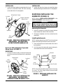
Spacers
Axle
Mounting
Screw
Patient Operated
Wheel Lock
Rear
Wheel
Wheelchair Frame
Locknut
FIGURE 3 - REMOVING/INSTALLING THE
REAR WHEELS - RECLINERS WITH
PATIENT OPERATED WHEEL LOCKS
Recliners With Attendant Operated
Wheel Locks (FIGURE 4)
REMOVING.
1. Remove the axle mounting screw and locknut that
secure the rear wheel and spacer to the wheelchair
frame.
FIGURE 4 - REMOVING/INSTALLING THE
REAR WHEELS - RECLINERS WITH
ATTENDANT OPERATED WHEEL LOCKS
Locknut
Wheelchair
Frame
Rear
Wheel
Axle
Mounting
Screw
Spacer
REMOVING/INSTALLING THE
ARMRESTS (FIGURE 5)
NOTE: Refer to INSTALLATION WARNINGS in the
SAFETY SUMMARY in this instruction sheet.
WARNING
Make sure the armrest release lever is in the
locked position before using the wheelchair.
Removing the Armrests
1. Unlock the armrest by turning the armrest release
levers towards the outside of the wheelchair.
2. Lift armrest completely out of arm sockets from the
wheelchair.
Installing the Armrests
NOTE: Armrest release levers MUST be in the unlocked
position when placing armrests into the arm sockets.
1. Place armrest into arm sockets located on the side of
the wheelchair.
2. Lock the armrest by turning the armrest release le-
vers towards the inside of the wheelchair.
Armrest
Release
Lever
Arm Socket
Arm
Socket
Armrest
Release
Lever
FIGURE 5 - REMOVING/INSTALLING THE
ARMRESTS
Armrest
NOTE: Only the adjustable height armrest is shown
for clarity. The fixed height armrest remove/install
in the same manner.
INSTALLING.
1. Secure rear wheel and spacer to wheelchair frame
with axle mounting screw and locknut. Securely tighten.
INSTALLING.
1. Secure rear wheel, patient operated wheel lock, and
spacers to wheelchair frame with axle mounting
screw and locknut. Securely tighten.

INVACARE CORPORATION l
ONE INVACARE WAY l
P.O. Box 4028 l
Elyria, Ohio 44036-2125
l
Phone 1-(800)-333-6900
Form No. 91-199 Part No. 1029377 Rev. (2) - 8/98 Printed in U.S.A.
INSTALLING THE TELESCOPING
I.V. ROD HOLDER - 2000, 4000
AND 9000 RIDELITE (FIGURE 6)
NOTE: Refer to INSTALLATION WARNINGS in the
SAFETY SUMMARY in this instruction sheet.
1. Remove the rear wheel from the wheelchair. Refer to
REMOVING/INSTALLING THE REAR WHEELS
in this instruction sheet.
2. Remove the arm from the wheelchair. Refer to RE-
MOVING/INSTALLING THE ARMRESTS in this in-
struction sheet.
3. Do one (1) of the following:
A. If arm tube does NOT contain arm release lever,
proceed to STEP 4.
B. If arm tube contains arm release lever, the spring
button and arm release lever MUST be removed
to ensure proper fit by performing the following:
a. Depress the spring button on the arm.
b. Slide the arm release lever to remove from
the arm.
c. Remove the plug button on the bottom of the
arm.
d. Depress the spring button on the arm.
e. Remove the spring from the arm.
f. Reinstall EXISTING plug button to the bottom
of the arm.
g. Proceed to STEP 4.
4. Remove the EXISTING pivot bolt and locknut that se-
cure the reclining back tube to the rear upright.
5. Install the NEW pivot bolt through the reclining back
tube and rear upright.
NOTE: The I.V. rod holder can be mounted on either side
of the wheelchair.
WARNING
Before installing the I.V. rod holder, en-
sure that the flat portion of the I.V. holder
is closest to the side frame of the wheel-
chair - otherwise injury or damage may
result.
6. Position the I.V. rod holder onto the EXISTING arm
socket as shown in FIGURE 6.
7. Securely tighten the I.V. rod holder to the wheelchair
with EXISTING locknut.
NOTE: When installing the I.V. rod support tube, en-
sure the adjustment knob is pointing out away from
the wheelchair.
8. Install the I.V. rod support tube into the I.V. rod holder.
9. Align the holes in the I.V. rod support tube with the I.V.
rod holder.
10. Install the mounting screw through the I.V. holder
and I.V. support rod support tube.
11. Install the locknut that secures the I.V. rod sup-
port tube and I.V. rod holder to the wheelchair.
12. Reinstall the arm to ensure proper fit. Refer to RE-
MOVING/INSTALLING THE ARMRESTS in this in-
struction sheet.
13. Securely tighten both locknuts of STEPS 5 AND 8.
14. Reinstall the rear wheel onto the wheelchair. Re-
fer to REMOVING/INSTALLING THE REAR
WHEELS in this instruction sheet.
15. Adjust I.V. rod to desired height. Refer to ADJUST-
ING THE I.V. ROD in this instruction sheet.
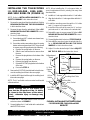
FIGURE 6 - INSTALLING THE TELESCOPING
I.V. ROD HOLDER - 2000, 4000 and 9000
RIDELITE
DETAIL “A”
Arm Release
Lever
Spring
Button
Arm
Tube
Plug Button
Pivot Bolt
EXISTING
Locknut
Reclining Back Tube
Rear
Upright
I.V. Rod
Support
Tube
I.V. Rod
Holder
Arm Socket
Locknut
Mounting
Screw
Adjustment
Knob
-
 1
1
-
 2
2
-
 3
3
-
 4
4


Invacare Veranda 4000 series User manual
- Type
- User manual
- This manual is also suitable for
Ask a question and I''ll find the answer in the document
Finding information in a document is now easier with AI
Related papers
-
Invacare 1110154 User manual
-
Invacare 9000 SL Owner's Operator And Maintenance Manual
-
-
-
-
-
-
-
-
Other documents
-
 Stryker Medical RUGGED 6080 MX–PRO Operation & Maintenance Manual
-
Stryker Power-PRO XT 6500 Operation & Maintenance Manual
-
-
Graham Field 565WG User manual
-
3M Ranger™ Irrigation Warming Unit 24700, Model 247, 120V-ENG-B Operating instructions
-
-
3M Food Warmer 245 User manual
-
Atrium 2450 User manual
-
Intermetro LEC9800 Installation guide
-
 level 1 H-1200 115V User manual

