Eaton Form 6 Operating instructions

Type
Operating instructions

This manual is also suitable for

Form 6 microprocessor-based rack-mount recloser control
installation and operation instructions
COOPER POWER
SERIES
Reclosers
MN280075EN
Effective July 2018
Supersedes May 2017
For type F6-R2 controls above serial number 20,000 or beginning with CP57.
COOPER POWER
SERIES
F6 Recloser Control
ii OPERATION AND INSTALLATION INSTRUCTIONS MN280075EN July 2018
DISCLAIMER OF WARRANTIES AND LIMITATION OF LIABILITY
The information, recommendations, descriptions and safety notations in this document are based on Eaton Corporations
(“Eaton”) experience and judgment and may not cover all contingencies. If further information is required, an Eaton sales
office should be consulted. Sale of the product shown in this literature is subject to the terms and conditions outlined in
appropriate Eaton selling policies or other contractual agreement between Eaton and the purchaser.
THERE ARE NO UNDERSTANDINGS, AGREEMENTS, WARRANTIES, EXPRESSED OR IMPLIED, INCLUDING WARRANTIES
OF FITNESS FOR A PARTICULAR PURPOSE OR MERCHANTABILITY, OTHER THAN THOSE SPECIFICALLY SET OUT IN ANY
EXISTING CONTRACT BETWEEN THE PARTIES. ANY SUCH CONTRACT STATES THE ENTIRE OBLIGATION OF EATON. THE
CONTENTS OF THIS DOCUMENT SHALL NOT BECOME PART OF OR MODIFY ANY CONTRACT BETWEEN THE PARTIES.
In no event will Eaton be responsible to the purchaser or user in contract, in tort (including negligence), strict liability or
other-wise for any special, indirect, incidental or consequential damage or loss whatsoever, including but not limited to
damage or loss of use of equipment, plant or power system, cost of capital, loss of power, additional expenses in the use of
existing power facilities, or claims against the purchaser or user by its customers resulting from the use of the information,
recommendations and descriptions contained herein. The information contained in this manual is subject to change
withoutnotice.
iiiOPERATION AND INSTALLATION INSTRUCTIONS MN280075EN July 2018
Contents
DISCLAIMER OF WARRANTIES AND LIMITATION
OF LIABILITY ...............................II
SAFETY FOR LIFE ..........................IV
SAFETY INFORMATION .....................IV
Safety instructions ..........................iv
PRODUCT INFORMATION .....................1
Introduction ............................... 1
ANSI standards ............................ 1
Quality standards. . . . . . . . . . . . . . . . . . . . . . . . . . . 1
Acceptance and initial inspection .............. 1
Handling and storage ........................ 1
Control power ............................. 1
FORM 6 RECLOSER CONTROL DESCRIPTION ....1
Description ............................... 1
Theory of operation ......................... 2
Control front panel .......................... 3
Control features ............................ 8
Communications ...........................11
Control information .........................11
Control back panel ..........................11
INSTALLATION PROCEDURE .................12
Initial programming prior to installation ......... 12
Control/recloser compatibility ................ 12
Duty cycle monitor ........................ 13
Mounting the control ....................... 13
Grounding the control ...................... 14
Customer connections for DC power and AC
voltage sensing .......................... 16
Before placing the control and the recloser
into service ............................. 20
Using removable inserts .................... 25
ACCESSORIES .............................27
Control cable ............................. 27
Recloser interface junction box ............... 27
Recloser interface junction box cable .......... 28
Discrete interface board (DIF) option accessory .. 32
Mounting kits ............................ 32
Communication board accessories ............ 36
TESTING ..................................38
Testing an installed control .................. 38
Remove the control from service ............. 39
Testing with type MET tester ................ 39
Closing the recloser during testing ............ 40
Return the control to service ................. 44
ADDITIONAL INFORMATION .................45
Replacement kits .......................... 45
Factory-authorized service centers ............ 45
Factory testing and troubleshooting classes ..... 45
iv OPERATION AND INSTALLATION INSTRUCTIONS MN280075EN July 2018
Form 6 microprocessor-based rack-mount recloser control
Safety for life
Eaton meets or exceeds all applicable industry standards relating to product safety in its Cooper Power™ series products.
We actively promote safe practices in the use and maintenance of our products through our service literature, instructional
training programs, and the continuous efforts of all Eaton employees involved in product design, manufacture, marketing, and
service.
We strongly urge that you always follow all locally-approved safety procedures and safety instructions when working around
high-voltage lines and equipment, and support our “Safety For Life” mission.
Safety information
The instructions in this manual are not intended as a
substitute for proper training or adequate experience in the
safe operation of the equipment described. Only competent
technicians who are familiar with this equipment should
install, operate, and service it.
A competent technician has these qualifications:
Is thoroughly familiar with these instructions.
Is trained in industry-accepted high- and low-voltage safe
operating practices and procedures.
Is trained and authorized to energize, de-energize, clear,
and ground power distribution equipment.
Is trained in the care and use of protective equipment
such as arc flash clothing, safety glasses, face shield,
hard hat, rubber gloves, clampstick, hotstick, etc.
Following is important safety information. For safe
installation and operation of this equipment, be sure to read
and understand all cautions and warnings.
Hazard Statement Definitions
This manual may contain four types of hazard statements:
DANGER
Indicates an imminently hazardous situation which, if
not avoided, will result in death or serious injury.
WARNING
Indicates a potentially hazardous situation which, if not
avoided, could result in death or serious injury.
CAUTION
Indicates a potentially hazardous situation which, if not
avoided, may result in minor or moderate injury.
NOTICE
Indicates a potentially hazardous situation which, if not
avoided, may result in equipment damage only.
Safety instructions
Following are general caution and warning statements that
apply to this equipment. Additional statements, related to
specific tasks and procedures, are located throughout the
manual.
DANGER
Hazardous voltage. Contact with hazardous voltage will
cause death or severe personal injury. Follow all locally-
approved safety procedures when working around high-
and low-voltage lines and equipment. G103.3
WARNING
Before installing, operating, maintaining, or testing this
equipment, carefully read and understand the contents
of this manual. Improper operation, handling, or
maintenance can result in death, severe personal injury,
and equipment damage. G101.0
WARNING
This equipment is not intended to protect human
life. Follow all locally-approved procedures and safety
practices when installing or operating this equipment.
Failure to comply can result in death, severe personal
injury, and equipment damage. G102.1
WARNING
Power distribution and transmission equipment must
be properly selected for the intended application. It
must be installed and serviced by competent personnel
who have been trained and understand proper safety
procedures. These instructions are written for such
personnel and are not a substitute for adequate training
and experience in safety procedures. Failure to properly
select, install, or maintain power distribution and
transmission equipment can result in death, severe
personal injury, and equipment damage. G122.2
WARNING
Overlapping zones of protection are required. Upstream
protection device settings must provide adequate
overcurrent protection in the event of a system or
product failure. Failure to properly select appropriate
upstream coordination protection can result in death,
severe personal injury, and equipment damage. G172.0
!
SAFETY
FOR LIFE
!
SAFETY
FOR LIFE
1OPERATION AND INSTALLATION INSTRUCTIONS MN280075EN July 2018
Form 6 microprocessor-based rack-mount recloser control
Product information
Introduction
Service Information MN280075EN provides installation and
operation instructions for the Form 6 microprocessor-based
rack mount recloser control above serial number 20,000 or
beginning with CP57.
Refer to the following information as appropriate for your
version of ProView software:
Service Information S280-70-4 Form 6 Recloser Control
Programming Guide: ProView 4.X.X software
Service Information S280-70-21 Form 6 Recloser Control
Programming Guide: ProView 5.X.X software
Read this manual first
Read and understand the contents of this manual and follow
all locally approved procedures and safety practices before
installing or operating this equipment.
Additional information
These instructions cannot cover all details or vari ations
in the equipment, procedures, or process described, nor
provide directions for meeting every possible contin gency
during installation, operation, or maintenance. When
additional information is desired to satisfy a problem not
cov ered sufficiently for the users purpose, contact your
Eaton representative.
ANSI standards
Eatons Cooper Power series reclosers are designed and
tested in accordance with the following ANSI standards:
C37.60 and C37.85 and ANSI Guide C37.61.
Quality standards
ISO 9001-Certified Quality Management System
Acceptance and initial inspection
Each Form 6 rack mount recloser control is completely
assembled, tested, and inspected at the factory. It is
carefully calibrated, adjusted and in good condition when
accepted by the carrier for shipment.
Upon receipt, inspect the carton for signs of damage.
Unpack the control and inspect it thoroughly for damage
incurred during shipment. If damage is discovered, file a
claim with the carrier immediately.
Handling and storage
Be careful during handling and storage of the control to
minimize the possibility of damage. If the control is to be
stored for any length of time prior to installation, provide a
clean, dry storage area. If storage is in a humid atmosphere,
make provisions to keep the control circuitry energized.
Control power
All operating power is obtained from the substation battery
bank. There are two power supply options available for the
Form 6 rack mount recloser control. Examine the voltage
decal on the back of the recloser control to verify the
correct voltage rating.
The following power supply options are available and
configured at the factory:
24 VDC ±20%
Burden 14 Watts
40 VDC –140 VDC
Burden 14 Watts
ote:N The 40 VDC – 140 VDC power supply is a universal
power supply adaptable for either 48 VDC or 125 VDC
substation batteries.
Refer to the Customer connections for DC power and
AC voltage sensing section of this manual for incoming
power wiring illustrations for the Form 6 rack mount
recloser control.
Form 6 recloser control description
Description
The Form 6 rack mount microprocessor-based recloser
control includes extensive system protection functionality,
including phase, ground, and negative sequence overcurrent
protection, over/underfrequency, and voltage protection,
directionality, sensitive ground fault, and sync check.
Analysis tools include fault locating, event recording, TCC
Editor II, Idea Workbench, and oscillography functions,
including oscillography replay.
Metering functions include demand and instantaneous
current on a per-phase basis, instantaneous voltage
and power factor on a per-phase basis, and power (real,
reactive,apparent).
The front panel LCD display is used to configure the
operating settings for the control. It is also used to display
metering, counter information, control parameters, reset
alarms, and provide diagnostic information.
Control parameters can also be programmed via a personal
computer connected to the control through the front panel
RS-232 port. Control programming, interrogation, and
operations are performed with Form 6 ProView interface
software on a personal computer.
The interface program software includes additional functions
used to create and graphically display Time Current Curves
and provide Idea Workbench for configuring user-selected
inputs and outputs, configurable event and alarm data, and
selectable communication points for serial communication.
The control operates on 50 and 60 Hz systems.
2 OPERATION AND INSTALLATION INSTRUCTIONS MN280075EN July 2018
Form 6 microprocessor-based rack-mount recloser control
The control can be configured, by the factory or by the
user, for a wide variety of applications. If user requirements
change, the control functions can be modified to meet the
new requirements.
Theory of operation
Current sensing is provided by three current transformers
located in the recloser and interfaced to the Form 6 recloser
control via control wiring. This wiring also supplies Trip,
Close, and Recloser status, and connects to the Recloser
Interface (RIF) module to provide isolation for reliable
operation. Voltages for metering are connected to the
analog board via the connector terminal block, TB-2.
A functional block diagram of the Form 6 recloser control
is shown in Figure1. Line current flowing through the
recloser is converted by the CPU module to a digital
signal suitable for metering and fault current calculations.
Data sampling occurs at a rate of 64 times per cycle. The
CPU contains a data acquisition section that uses the
acquired samples to compute the fundamental currents
and voltage for use in overcurrent, under/overvoltage, and
under/overfrequency protection, as well as currents and
voltages for metering functions. The current for overcurrent
protection is calculated on a sub-cycle basis; it includes only
the fundamental and DC component.
TRIP SOLENOID
CLOSE SOLENOID
A Ø CT
B Ø CT
C Ø CT
OPEN / CLOSE
SWITCHES
CT COMMON
RECLOSER
POWER
28 VDC
AUXILIARY
POWER
OUTPUT
INTERCON-
NECTION
BOARD
CPU
FRONT
PANEL
RS-232
(PROVIEW
PROTOCOL
ONLY)
24, 48/125 VDC
POWER INPUT
CONNECTIONS
3 inputs
USER
CONNECTIONS
5 outputs
8 inputs
USER
CONNECTIONS
8 outputs
MATCHING
TRANSFORMERS
AND SIGNAL
CONDITIONING
ANALOG INPUT
RIF
OPTICAL
ISOLATION
OPTICAL
ISOLATION
OPTICAL
ISOLATION
OPTICAL
ISOLATION
USER
VOLTAGE
SENSING
4 inputs
I/O
ACCESSORY
RS-232
IRIG-B
COMMUNICATIONS
BOARD ACCY
•RS-485
•FIBER-OPTIC
•ETHERNET
Figure1. Form 6 rack mount recloser control operational flow diagram
When the phase or ground current exceeds its programmed
minimum-trip value and associated time-current-curve (TCC)
timing, the control initiates the programmed sequence of
recloser tripping and reclosing operations via the CPU and
RIF modules. If the fault is temporary, the control resets
to the start of its operating sequence after a preset time
delay. If the fault is permanent, the control performs its
complete programmed sequence of reclose commands
and locks out with the recloser open. Once locked out, the
control must be closed via the operator panel or SCADA
communications. This resets the control to the start of the
operating sequence.
The following chain of events occurs for an operating
sequence of two trips to lockout (one trip on TCC1,
one trip on TCC2):
1. The overcurrent signal is integrated with time on the
selected curve for the first trip operation (TCC1) to
produce the signal which energizes the trip circuit.
2. Energizing the trip circuit connects the supply to the
trip solenoid to open the recloser.
3. Upon opening, the control starts timing on the first
reclosing interval-delay time.
4. Upon expiration of this reclosing interval-delay, a closing
signal is issued from the control, closing the recloser,
and selecting the time-current characteristics for the
second trip operation (TCC2).
5. If current remains above the minimum-trip level, the
recloser will trip on TCC2 and lockout the recloser.
3OPERATION AND INSTALLATION INSTRUCTIONS MN280075EN July 2018
Form 6 microprocessor-based rack-mount recloser control
Control front panel
The Form 6 control front panel is illustrated in Figure2.
The front panel is separated into two clearly identified, color-
coded sections:
The top portion of the front panel is used for programming
the control and providing LED status indication.
The lower portion of the front operating panel is used for
operating the control and recloser.
The control includes a Power Save feature that will turn off
the backlit LCD display and all LEDs (except Hot Line Tag) if
no front panel keypad is pressed within ten minutes. Pressing
the LAMP TEST key will re-activate the display andLEDs.
ote:N The Power Save feature is a ProView interface
software default setting. This feature can be disabled
via the ProView interface software.
The control includes a Reset Menu feature that will cause
the LCD display to revert to the root menu after ten minutes
of inactivity.
ote:N The ten minute timer and MMI Reset Menu is a
ProView interface software default setting. The menu
selection and timer can be changed via the ProView
interface software.
CONTROL POWER
CONTROL OK
CONTROL LOCKOUT
RECLOSER OPEN
RECLOSER CLOSED
A PHASE FAULT
B PHASE FAULT
C PHASE FAULT
GROUND FAULT
SENSITIVE GND
ALARM
ABOVE MIN TRIP
INDICATOR 1
INDICATOR 2
INDICATOR 3
A PHASE VOLTAGE
B PHASE VOLTAGE
C PHASE VOLTAGE
FREQUENCY TRIP
VOLTAGE TRIP
METERING
RESET
TARGETS
EVENTS
LAMP TEST
MENU
ENTER
+
SETTINGS
OPER
COUNTER
ALARMS
CHANGE
F1 F2 F3 F4
TRIP CLOSE
HOT LINE TAG
ON
GND TRIP
BLOCKED
NON
RECLOSING
SUPERVISORY
OFF
ALTERNATE
PROFILE #1
ALTERNATE
PROFILE #2
ALTERNATE
PROFILE #3
RS-232 DATA PORT
OPTION #1
OPTION #2
OPTION #3
(LOCKOUT)
LCD Display
LCD Display
Dedicated
Function Keys
One-Touch
Analysis Keys
Hot Line Tag Toggle Switch and
Three-Segment LED Indication
RS-232
Configuration
Data Port
CLOSE Pushbutton
TRIP (LOCKOUT)
Pushbutton
(Hardwire Connected)
LED Indicators
LCD Display
Dedicated
Function Keys
One-Touch
Function Keys
Cursor Movement Arrows
LCD Menu Function Keys
One-Touch
Analysis Keys
INDICATOR 4
INDICATOR 5
INDICATOR 6
INDICATOR 7
INDICATOR 8
CLOSE CIRCUIT
DISABLE
Close Circuit
Disable Fuse
and Fuseholder
F6 Recloser Control
COOPER POWER
SERIES
Figure2. Form 6 recloser control front panel
4 OPERATION AND INSTALLATION INSTRUCTIONS MN280075EN July 2018
Form 6 microprocessor-based rack-mount recloser control
Front panel text messaging
The LCD messages are accessed from the front panel by
following the Text Messages menu path. This menu displays
any active user-configured text messages.
Up to fourteen user-configurable text messages can be
programmed via the Idea Workbench. Refer to Service
Information S280-70-4 (ProView 4.X.X) or S280-70-21
(ProView 5.X.X) Form 6 Control Programming Guide for
information on programming the text messages.
These text messages appear on the front panel LCD and
can be programmed to appear for alarm or other conditions.
Text messages displayed on the front panel are limited to
four lines of 20 characters each (including spaces). Text
messages can also be accessed by pressing the LAMP
TEST one-touch analysis key on the front panel.
Programming panel
The Programming panel has the following sections:
One-touch analysis keys
There are eight analysis keys (Figure3) that allow
one-button access to a variety of control and monitoring
functions that appear in the LCD display. Pressing these
buttons causes the following information to display or
function to occur:
ote:N When pressing a membrane pushbutton, always
press and hold for 0.5 seconds to ensure the button
press is recognized by the device.
METERING: Displays the systems instantaneous metering
values for current and voltage on the LCD display.
RESET TARGETS: Resets the fault target indicators on the
operator panel.
EVENTS: Displays the last 25 events from the Sequence of
Events log.
LAMP TEST: All operator panel LEDs are illuminated for
verification of proper connection and operating status of all
indicator lights. All status indicators will then return to their
previous state. While in the LAMP TEST mode, the control
response to operator panel keys is disabled, except for the
TRIP (LOCKOUT), CLOSE, and HOT LINE TAG switches.
SETTINGS: Displays recloser settings on the LCD display.
METERING
RESET
TARGETS
EVENTS
LAMP TEST
MENU
ENTER
+
SETTINGS
OPER
COUNTER
ALARMS
CHANGE
F1 F2 F3 F4
Figure3. Analysis keys, LCD display, LCD menu function
keys, and cursor movement arrows
OPER COUNTER: Displays the total number of trip
operations and target counters for each A, B, and C Phase;
Ground, and Sensitive Ground on the LCD display.
ALARMS: Provides status information on the LCD display
for all recloser alarms.
CHANGE: Allows the user to change the state of the control
functions on the operator panel function keys.
ote:N The CHANGE mode is a ten second period in which
one function setting can be changed. If no change
is made in that time, the control returns to the
currentsetting.
LCD Display
The LCD Display is a backlit 4-line, 20-character display that
provides extensive distribution system, recloser, and control
status information using a minimum of eight navigation
keypads (Figure3).
ote:N The LCD display panel contrast is field-adjustable to
allow for various mounting heights and applications.
Press the MENU key and then press the (+) or (–)
key to increase or decrease the contrast.
The four LCD navigation buttons are as follows:
MENU Identifies the LCD Display menu options.
ENTER Selects a menu option.
+ Increases value selection.
– Decreases value selection.
The four LCD menu function keys activate specific menu
commands. When a command appears in the LCD display
directly above one of the four LCD menu function keys, the
user can press the key to accept/select the command.
The four LCD menu function keys are as follows:
F1 F2 F3 F4
The four cursor movement arrows allow movement in the
following directions:
Moves the cursor left.
Moves the cursor right.
Moves the cursor up one line.
Moves the cursor down one line.
Status indicator LEDs
The status indicator LEDs (Figure4) in the Programming
section of the Operator Panel give instant information on
the control and recloser status:
All of the default status indicators LEDs (except for
CONTROL OK, CONTROL POWER, and ALARM) can be
reconfigured via the Idea Workbench. Refer to Service
Information S280-70-4 (ProView 4.X.X) or S280-70-21
(ProView 5.X.X) Form 6 Control Programming Guide for
additional information.
5OPERATION AND INSTALLATION INSTRUCTIONS MN280075EN July 2018
Form 6 microprocessor-based rack-mount recloser control
The label inserts can be user-customized. Refer to
Using removable inserts section of this manual for
additionalinformation.
CONTROL OK: The green LED indicates the control is
operating normally and not in an alarm state.
The CONTROL OK LED will not be illuminated during these
alarms (indicated by the red ALARM LED and displayed in
the alarm status log):
RAM Failure: This alarm indicates a failed RAM
memory test.
ROM Failure: This alarm indicates a failed ROM
memory test.
Power Supply Malf[unction]: This alarm indicates internal
control operation power was outside of its operating
tolerance for more than 20 seconds. This alarm resets
when the internal control operation power returns to
operation within its normal tolerances.
CONTROL POWER: The green LED indicates there is
adequate VTC voltage to trip the recloser. This LED does not
indicate the presence of AC or battery power.
CONTROL LOCKOUT: The green LED indicates the control
is in a locked out state, i.e. a reclosing sequence is not in
progress. This LED does not indicate that the recloser isopen.
RECLOSER OPEN: The green LED indicates the recloser is
in the open position.
RECLOSER CLOSED: The red LED indicates the recloser is
in the closed position.
ote:N There are several conditions that will cause the
alternate blinking of the CONTROL LOCKOUT,
RECLOSER OPEN, and RECLOSER CLOSED
LEDs: Failure to Trip, Failure to Close, Interrupter
Malfunction, and 52a/b Disagreement.
The LED blinking pattern for these conditions is the
CONTROL LOCKOUT green LED and RECLOSER
CLOSED red LED alternating with the RECLOSER
OPEN green LED.
In addition to the above LED blinking pattern,
the red ALARM LED will also be illuminated for
these alarms: Failure to Trip, Failure to Close, and
Interrupter Malfunction.
A PHASE FAULT, B PHASE FAULT, C PHASE FAULT: The red
LEDs indicate A, B, and/or C phase current was either the
maximum phase current or within 20% of the maximum
when a trip signal was issued.
GROUND FAULT, SENSITIVE GROUND FAULT: The red
LEDs indicate that a Ground and/or Sensitive Earth Fault
tripping function was asserted at the time the trip signal
wasasserted.
ALARM: The red LED indicates an alarm has been issued.
Review the alarm status and log on the LCD display for the
specific alarm.
ote:N If a Battery Alarm occurs, de-select the Pole
Mounted Control checkbox in the ProView application
software Configure>System Configuration dialog
box. Refer to Service Information S280-70-4 (ProView
4.X.X) or S280-70-21 (ProView 5.X.X) Form 6 Control
Programming Guide foradditional information.
ABOVE MINIMUM TRIP: The red LED indicates the current
exceeds the level set for minimum trip.
FREQUENCY TRIP: Indicates the recloser tripped due to an
under or over frequency condition.
VOLTAGE TRIP: Indicates the recloser tripped due to an
under or over voltage condition.
A PHASE VOLTAGE, B PHASE VOLTAGE, C PHASE
VOLTAGE: The red LED indicates a presence of voltage
on the respective phases. The Single-Phase Undervoltage
Pickup setting controls the voltage indication for the front
panel LEDs as defined in the Voltage setting dialog box for
the active setting profile. Refer to Settings - Voltage in the
Schemes section of S280-70-4 (ProView 4.X.X) or S280-70-21
(ProView 5.X.X) Form 6 Control ProgrammingGuide.
INDICATOR 1, INDICATOR 2, INDICATOR 3, INDICATOR4,
INDICATOR 5, INDICATOR 6, INDICATOR 7, INDICATOR8:
Customizable LEDs that are used with functions programmed
through the Idea Workbench. The LED indicators do not have
active default values. The LEDs are illuminated when the
status configured via the Idea Workbench is present.
Operating panel
The Operating section includes the following sections:
RS-232 configuration data port
The RS-232 connector (shown in Figure2) on the front
operating panel allows direct connection to a personal
computer without any special cables or connectors. This
port is used only for configuring the control with ProView
application software. All settings, metering, events, and
oscillography data are available from this port. The port is
Data Communication Equipment (DCE) wired for direct
connection to a personal computer.
A 9-pin RS-232 cable (Catalog Number KME5-66) to
connect from the PC to the RS-232 data port is available as
an accessory.
CONTROL POWER
CONTROL OK
CONTROL LOCKOUT
RECLOSER OPEN
RECLOSER CLOSED
A PHASE FAULT
B PHASE FAULT
C PHASE FAULT
GROUND FAULT
SENSITIVE GND
ALARM
ABOVE MIN TRIP
INDICATOR 1
INDICATOR 2
INDICATOR 3
A PHASE VOLTAGE
B PHASE VOLTAGE
C PHASE VOLTAGE
FREQUENCY TRIP
VOLTAGE TRIP
INDICATOR 4
INDICATOR 5
INDICATOR 6
INDICATOR 7
INDICATOR 8
Figure4. Status indicator LEDs
6 OPERATION AND INSTALLATION INSTRUCTIONS MN280075EN July 2018
Form 6 microprocessor-based rack-mount recloser control
HOT LINE TAG ON/OFF Toggle Switch and LED Indicator
WARNING
Hazardous voltage. Do not use Hot Line Tag as
a substitute for a visible disconnect. Always
establish a visible disconnect prior to performing
any work requiring a de-energized line. Failure to
comply may cause death, severe personal injury, or
equipmentdamage. T276.0
Hot Line Tag is provided for live-line work applications. All
closing operations are disabled when the Hot Line Tag
feature is activated.
IMPORTANT
Hot Line Tag activation does not cause the recloser to trip
open. It only prevents the recloser from closing.
IMPORTANT
Hot Line Tag is intended solely for live-line work applications,
such as maintenance, repairs or improvements to the
distribution system, that occur while the line remains
energized.
Hot Line Tag prevents all closing attempts from the control
and shifts protection to one trip-to-lockout on the composite
curve of the Hot Line Tag definite time and the TCC1 curve
(whichever is faster). Hot Line Tag takes precedence over
Cold Load Pickup, Non-Reclosing, and Fast Trips Disabled.
Hot Line Tag is activated from either the operator panel
toggle switch, serial communications, or a discrete SCADA
function. All sources must be off to de-activate Hot Line Tag.
To activate the function from the operator panel, flip toggle
switch up to the ON position. See Figure5. The LED
indicator illuminates when the function is active.
The Hot Line Tag function may only be reset by the source
which initiates it. For example, if Hot Line Tag is activated at
the operator panel, the reset function is only possible at the
operator panel, and not via SCADA command.
Close circuit disable
Close Circuit Disable (Figure5) is a removable fuse that,
when removed from the front operating panel, disables
the close circuit from the control to the recloser. Removing
the cartridge from the control disables all electrical closing
of the recloser and provides a physical disconnect to the
recloser closing circuit. As a result, the control cannot
perform a close operation. This disconnect overrides all
close functions and makes a remote or manual close
operation impossible.
ote:N When the Close Circuit Disable fuse is removed,
the trip circuit remains active and will trip
per the programmed time current curve for a
faultedcondition.
IMPORTANT
If the CLOSE button is pressed after the Close Circuit
Disable fuse is removed, do not reinstall the fuse until after
the ALARM LED illuminates (within approximately five
seconds) to indicate CLOSE MALFUNCTION. Re-installing
the Close Circuit Disable fuse prior to the CLOSE
MALFUNCTION ALARM indication will cause the control to
close the recloser.
TRIP (Lockout) pushbutton
The TRIP pushbutton (Figure5) provides front-panel
access to trip (lockout) the recloser. When pressed, the
TRIP pushbutton opens the recloser and locks out the
control. The TRIP pushbutton operates independent of the
microprocessor and is directly connected to the trip coil
circuitry in the recloser.
ote:N In the event of microprocessor failure, the trip circuit
can operate independent of the main microprocessor.
CLOSE pushbutton
When pressed, the CLOSE pushbutton (Figure5) returns
the control to the initial or home sequence position, closing
the recloser. The control is ready for the start of a new trip/
close sequence.
ote:N The Close Malfunction alarm must be reset before
Closing will be allowed.
ote:N Pressing the CLOSE pushbutton from the Lockout
position initiates Cold Load Pickup (CLPU) protection,
if the feature is enabled.
The user does have the ability to block COLD LOAD
PICKUP through the LCD menu or by configuring one
of the Option one-touch function keys via the Idea
Workbench feature in ProView.
If the recloser is closed, pushing and holding the
CLOSE pushbutton does not activate the Cold Load
Pickup feature. See Cold Load Pickup in the Control
Features section of this manual.
TRIP CLOSE
HOT LINE TAG
ON
CLOSE
CIRCUIT
DISABLE
(LOCKOUT)
COOPER POWER
SERIES
Figure5. TRIP (Lockout) pushbutton; CLOSE
pushbutton; Close Circuit Disable removable fuse; and
Hot Line Tag switch and Hot Line Tag red indicator LEDs
7OPERATION AND INSTALLATION INSTRUCTIONS MN280075EN July 2018
Form 6 microprocessor-based rack-mount recloser control
One-touch function keys
Quick access to frequently operated Form 6 control features
is provided with nine function key pushbuttons on the
control operator panel.
The Form 6 control operator panel one-touch function keys
are illustrated in Figure6.
GND TRIP
BLOCKED
NON
RECLOSING
SUPERVISORY
OFF
ALTERNATE
PROFILE #1
ALTERNATE
PROFILE #2
ALTERNATE
PROFILE #3
OPTION #1
OPTION #2
OPTION #3
Figure6. Operator panel function keys
Red LEDs located on each function key indicate the status
of the function, regardless of local or remote activation. For
example, if Ground Trip Blocked is activated from a SCADA
signal, the red indicator will illuminate even though it was
not activated from the operator panel.
Operator panel function key activation or de-activation
requires the operator to first press the CHANGE key to
enter the CHANGE mode. A function must then be selected
or de-selected within ten seconds to activate or de-activate
the function. Once selected, the control returns to normal
operation until prompted for another change request. This
prevents accidental changing of functions or features.
ote:N Only one function can be changed per each CHANGE
mode activation.
GND TRIP BLOCKED
The Ground Trip Blocked function blocks all ground sensing
in the control for the active profile. This red indicator is
illuminated when Ground Trip Block is activated from the
serial port, I/O, the interface software, or locally (via the
front panel) causing the control to block all ground sensing.
NON RECLOSING
The control is operating in a non-reclosing mode when the
NON RECLOSING red indicator is illuminated. Non-reclosing
mode disables any automatic reclosing operations.
Non-reclosing does not alter the active TCC. Activation is
possible from the SCADA port, I/O, the interface software,
or locally (via the front panel).
SUPERVISORY OFF
When the SUPERVISORY OFF red indicator is illuminated,
supervisory commands are blocked. Supervisory functions
through the back panel serial communication ports and the
discrete I/O are blocked. Serial communications through
the front panel RS-232 port remain active independent of
the status of the SUPERVISORY OFF switch. Activation
of this function key is restricted to the operator panel and
is accomplished by pressing the CHANGE key and then
pressing the SUPERVISORY OFF key. Operational data
and metering information are available while the control is
in the SUPERVISORY OFF position. The TRIP and CLOSE
pushbuttons and Hot Line Tag are active independent of the
SUPERVISORY OFF function.
ALTERNATE PROFILE #1, #2, AND #3
The Form 6 control has four separate protection profiles;
a Normal profile, and Alternate Profiles 1, 2, and 3. Each
profile changes all protection parameters for the control.
Except for the normal profile, each has an indication and
selection key. When the operator panel display lights are
active and none of the three indicators are on, the normal
profile is active. Only one profile can be active.
To select an alternate profile, press the CHANGE key and
then press the desired alternate profile.
To return to the normal profile, press the CHANGE key
and then press the active alternate profile to deselect
it. These functions can also be completed remotely via
communications interfaces.
IMPORTANT
Unused alternate profiles should be programmed with the
same settings as one of the applicable profiles. Default
settings on unused alternate profiles can cause unnecessary
outages if they are below normal systemrequirements.
IMPORTANT
Check minimum trip values prior to changing an alternate
profile to avoid misoperation of the control under load
conditions.
OPTION #1, OPTION #2, AND OPTION #3
The OPTION #1, OPTION #2, and OPTION #3 function
keys must be programmed via the ProView Idea
Workbenchsoftware.
The OPTION LEDs are illuminated when the options
configured via the Idea Workbench are selected. Refer
to Service Information S280-70-4 (ProView 4.X.X) or
S280-70-21 (ProView 5.X.X) Form 6 Control Programming
Guide for additional information.
These OPTION keys provide a momentary signal. For
instance, these keys can be programmed to toggle control
status, protective functions, or a momentary input pulse.
The OPTION #1, OPTION #2, and OPTION #3 function
keys are intentionally not defaulted to any function. The
functions are assigned to each OPTION key via the Idea
Workbenchapplication.
8 OPERATION AND INSTALLATION INSTRUCTIONS MN280075EN July 2018
Form 6 microprocessor-based rack-mount recloser control
Control features
The Form 6 recloser control offers numerous standard
features and accessories that allow the user the utmost
flexibility applying the recloser control.
Control security
The Form 6 recloser control has multiple customer-
programmable security codes to limit control programming
and viewing function access to authorized personnel. The
front panel Human-Machine Interface (HMI) includes a
user-selected security code to access the settings. Plus, the
ProView interface software has it’s own security levels for
multiple-user access.
Refer to Service Information S280-70-4 (ProView 4.X.X) or
S280-70-21 (ProView 5.X.X) Form 6 Control Programming
Guide for additional information.
Protection profiles
Four protection profiles capable of fully specifying control
operation are standard in the control. Each protection profile
includes the following as a minimum:
Overcurrent Protection
Over/Undervoltage Protection
Over/Underfrequency Protection
Directional Protection
Hot Line Tag Functionality
Sync Check
Sensitive Earth Fault Protection
Sequence Coordination
Operation Settings
Time current curves
Time-current curves are available for numerous functions,
including fast and delayed operations for phase, ground, and
negative sequence protection. Each time-current is selected
from a defined fifty curves which can be further customized
by the user. The time-current curves are also selected from
a graphical TCC Editor II to visualize any modifications prior
to configuring the control.
The time-current curves include the following modifications
for phase, ground, and negative sequence protection:
Time Multiplier with a range of 0.1 to 25 in .1 increments.
Time Adder with a range of 0 to 30 seconds in .01
second increments.
Minimum Response Time with a range of 0.1 to 1
seconds in .001 second increments.
High Current Trip multiplier with a range of 1 to 32
multipliers in increments of 0.1.
High Current Trip Time Delay with a range of 0.01 to .150
seconds in .001 second increments.
Time Dial Reset co-efficient with a range of .1 to 30
seconds in 1 second increments.
Sequence coordination
Sequence Coordination eliminates nuisance tripping through
trip coordination. It allows the control to step through
selected operations in the operating sequence without
tripping. The number of Sequence Coordination advances
is programmable from one to three operations to provide
trip coordination with a downline recloser. This feature is
independently selectable for each protection profile.
Cold load pickup
The control includes a Cold Load Pickup feature to prevent
the control from tripping while energizing non-fault system
loads. This feature has independently programmable
minimum trip value time-current curve, reclose interval,
and number of independent operations to lockout for
each protection profile. Cold Load Pickup also includes
TCC Multipliers, TCC Adders, Minimum Response Time,
Time Dial Reset, and High Current Lockout. Also, direct
values, not multiples of minimum trip, are provided for high
current lockout.
Fast trips disabled
The control includes a Fast Trips Disabled feature to modify
protection, so that all trip operations use the programmed
TCC2. This feature is independently selectable for each
protection profile. All trip operations will time on TCC2.
Typically, TCC1 is fast and TCC2 is delayed. So, as an
example, the control will change it’s sequence from 2 fast
and 2 delayed operations to 2 operations on TCC2 when
Fast Trips Disabled is active.
High current lockout
The High Current Lockout feature will automatically lockout
the control on the selected operation when current
exceeds a programmable level. The active trip numbers for
the lockout is selectable for phase, ground, and negative
sequence. This feature is independently selectable for each
protection profile.
Sensitive ground/earth fault operation
The control has a Sensitive Ground/Earth Fault Trip feature
that provides tripping of the recloser after a programmable,
definite time for ground currents below normal ground
minimum trip levels. The feature has programmable
operations to lockout and reclose intervals independent of
the ground settings. This feature is independently selectable
for each protection profile.
9OPERATION AND INSTALLATION INSTRUCTIONS MN280075EN July 2018
Form 6 microprocessor-based rack-mount recloser control
Metering
The control provides instantaneous and/or demand
metering with programmable integration intervals for the
followingfunctions:
Real and reactive power for each phase and total,
including directional, on an individual phase basis.
Demand currents on a per phase basis.
Instantaneous currents, including ground current.
Instantaneous voltage on a per phase basis.
Instantaneous frequency.
Positive, negative, and zero sequence voltages.
Instantaneous power factor on a per phase basis.
Metering settings to include demand interval, and alarm
thresholds for current, single-phase kW, three-phase kW,
single-phase kvar, and three-phase kvar.
Event recorder
The Form 6 control contains capabilities to perform
Sequence of Events time-stamping for up to 33 event
types. Sixteen additional inputs can be user-defined through
the Idea Workbench.
Factory-defined event types include:
Overcurrent Protection Trip
External Trip
Non-Reclose Trip
External Close
Lockout
Reset
The Event Recorder maintains a minimum of 90 event
records. The last 25 events are viewable on the front
panel LCD display. Refer to Service Information S280-70-4
(ProView 4.X.X) or S280-70-21 (ProView 5.X.X) Form 6
Control Programming Guide for additional information.
Recloser duty monitor
The Form 6 recloser control software is equipped with
a Recloser Interrupting Duty Monitor. The Duty Monitor
accumulates the summation of I
1. 5
for all interrupted
currents on each interrupter. This feature permits
programmable entries to preset the duty of an existing
recloser. The recloser duty monitor displays interrupting duty
in percent of duty used. If the duty cycle monitor exceeds
100%, the recloser should be examined for maintenance.
Discrete SCADA communications
The control provides five configurable output status contacts
and three configurable input control contacts as standard.
Each status contact is configurable using graphical interface
software to combine status functionality along with Boolean
algebra. Default output status contacts are: Lockout,
Recloser Open, Recloser Closed, Ground Trip Block, and Hot
Line Tag. One output status contact is a solid state output
(SS1) with a pickup time no longer than twomilliseconds.
The control also provides a minimum of three configurable
input control contacts. Each control contact is configurable
using ProView application software. Contacts accept a
whetting voltage range of 9 VDC - 290 VDC, 7 VAC - 265
VAC. Each digital input is configured for either a momentary,
maintained, or maintained with precedence contact. Default
input control contacts are: Supervisory Trip and Lockout,
Supervisory Close, and Remote Trip and Lockout.
A Discrete Interface Board is also available as an accessory
to provide an additional eight output status contacts and
eight input control contacts. The expansion I/O board is
completely user-configurable.
TCC Editor II
Coordination and actual time current modifications are
available with a graphic interactive TCC Editor or similar
graphical software.
The TCC Editor II includes a complete database of standard
recloser industry time current curves (TCC), both ANSI and
IEC types, along with the ability to customize the TCCs with
multipliers, constant time adders, or minimum response time
adders. Also, the user is able to derive their own specific TCC
through data point entry. Each modified time current curve can
be identified with a user-customized name and is selectable
for configuring the control. The grid and format for presenting
the TCCs has a user-adjustable scale, including the option of
presenting multiple TCCs in various user-configured colors.
Oscillography
Oscillography is provided to present current and voltage
waveforms, along with protection element and recloser
response status changes. Filtered and unfiltered data are
provided for viewing.
The recorded values are super-imposed on the protection
scheme, and the state or value at any point in the scheme is
displayed. The user has the capability to move through the
event and watch the response of every function. All analog
signals, digital inputs, and contact outputs are monitored.
Analog oscillography is displayed at 16 samples per cycle.
Oscillographic data is recorded to analyze multiple
events during a permanent fault or other event type. The
oscillographic data shows two cycles before the trigger
point and eight cycles after the trigger point (default).
ote:N The configuration settings are programmable.
Oscillography automatically initiates trigger points for the
following functions:
Above Minimum Trip for Phase, Ground, and Sensitive
Ground Fault
Single and Three-Phase Overvoltage
Single and Three-Phase Undervoltage
10 OPERATION AND INSTALLATION INSTRUCTIONS MN280075EN July 2018
Form 6 microprocessor-based rack-mount recloser control
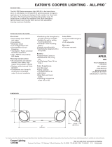
Over and Underfrequency
Trip Signal Issued
Close Signal Issued
Removable inserts
Removable inserts are included with the control design
for customization of specific protection requirements.
Inserts are available for the status indicator LEDs, the
operator panel function keys, and the analysis keys.
The removable inserts are designed for use without
adhesives, labelmakers, or temporary labels. Refer to
Using removable inserts section in this manual for more
information.
An electronic label template is included on the ProView
application software CD and can be accessed through the
following default address: C: / Program Files / Cooper /
ProviewXX / Form6 / Form 6 Inserts.doc
Idea workbench
The Idea Workbench provides access to various inputs,
intermediate variables, and internal Form 6 alarms, status,
and targets to allow user-customization of the Form 6
recloser control to meet specific and unique applications.
Idea Workbench also gives the user the ability to perform
logical functions with these variables by using a simple
graphical user interface. Use of Idea Workbench is not a
requirement for operation.
Refer to Service Information S280-70-4 (ProView 4.X.X) or
S280-70-21 (ProView 5.X.X) Form 6 Control Programming
Guide for additional Idea Workbench information.
Over/underfrequency protection
The control includes two-stage operation for both
underfrequency and overfrequency protection. A fixed
time delay ranging from 0 to 100 seconds in .001 second
increments is available for both over and underfrequency.
A frequency restoration function, enabled or disabled by
the user, is provided to allow the recloser to automatically
close should frequency return to within configured settings
for a user-settable time. Over/Underfrequency Protection is
included as part of each protection profile.
Over/undervoltage protection
The control includes single-phase and three-phase
undervoltage tripping. The control also includes three-phase
overvoltage tripping. Both over and undervoltage functions
include a single-phase and three-phase pick-up setting; a
single-phase and three-phase time delay setting ranging
from 0 to 100 seconds.
Directional
Directional functionality is included to maintain system
coordination from multiple sources, as well as circuit
reconfiguration for each profile. Directional applies to
phase, ground, and negative sequence protection, selected
independently. A maximum torque angle has a range of
0 – 90 degrees.
Fault location
The control includes an impedance-based fault locator
based upon the Takagi algorithm
1
. Load-compensated
impedance calculation is used for calculating the distance.
Positive and zero sequence is configured in ohms, and the
fault locator line length is configured in kilometers/miles.
1
T. Takagi, Y. Yamakoshi, J. Baba, K. Uemura, T. Sakaguchi,
A New Algorithm of an Accurate Fault Location for EHV/
UHV Transmission Lines: Part I - Fourier Transformation
Method”, IEEE Trans. on PAS, Vol. PAS-100, No. 3,
March1981, pp1316-1323.
Sync check
Sync Check is a permissive system used to qualify any
close signal to the mechanism when enabled via the
sync check settings. Sync check allows for closing for
any combination of dead/live bus/line, and to perform
anticipatory closing for a live bus/live line condition by
calculating slip and anticipating the mechanism closing
delay. In addition to the anticipatory close calculation, the
sync check system performs verification of line and bus
voltage magnitudes and frequencies to determine that they
are within pre-determined ranges, and that the angular
difference between the two systems is also within the
pre-determined range. For a live/live close, where there
is no slip between the systems, the sync check system
allows permissive closing after the two systems are within
frequency and voltage limits, and the angular difference
between the systems has been within the allowable limits
for a pre-determined time.
Sync Check functionality includes the following applications:
Hot Line/Hot Bus Closing; Dead Line/Hot Bus Closing; Hot
Line/Dead Bus Closing; and Dead Line/Dead Bus Closing.
Sync Check Parameters include the following configurable
settings: Voltage Angle; Mechanism Operating Delay; Static
Angle Delay; Dead Threshold; Live Threshold; Positive
Sequence Dead Threshold; Upper Voltage Limit; Lower
Voltage Limit; Lower Frequency Limit; Upper Frequency
Limit; and Fail to Close Timer.
Data profiler
A fully-configurable data profiler is available which allows the
user to collect information by sampling data at selectable
intervals. These time-stamped values can then be viewed to
determine weekly load profiles, daily harmonic disturbances
or hourly voltage fluctuations. The number of days of
information the data profiler can provide depends upon
configuration parameters.
Refer to Service Information S280-70-4 (ProView 4.X.X) or
S280-70-21 (ProView 5.X.X) Form 6 Control Programming
Guide for additional information.
11OPERATION AND INSTALLATION INSTRUCTIONS MN280075EN July 2018
Form 6 microprocessor-based rack-mount recloser control
Manual close delay
Manual Close Delay provides a delay from the time that the
manual CLOSE button is pushed to the time the manual
close operation is performed.
The delay is programmable from 0 to 60 seconds in 1
second increments. A programmed delay value can be
overridden for immediate closing by pressing the CLOSE
button a second time.
An active Manual Close Delay can be canceled by pressing
the TRIP/LOCKOUT button.
The default setting has the feature disabled (0 seconds). A
countdown on the front panel LCD screen indicates Manual
Close Delay is active.
Communications
Communication ports
The Form 6 control has two back panel communication
ports and a front panel configuration data port.
The front panel configuration data port is described in the
Operating Panel section of this manual.
There is one standard 9-pin RS-232 and one optional
communication port (RS-485, serial fiber, Ethernet wire
or fiber or both) on the back operator panel, as well as a
standard IRIG-B port for user time-syncing. See Figure7.
Communication protocols
Four communication protocols are available for the Form 6
recloser control:
Modbus
DNP3
2179
IEC870-5-101
One communication protocol can be selected for either the
back panel RS-232 or the optional communication port.
All four protocols are selected and configured by the
user with the ProView Communications Workbench
applicationsoftware.
Ethernet communications
ProView over TCP/IP
DNP3 over TCP/IP
Ethernet connection allows for network application of
the Form 6 control for both DNP3 and ProView protocols.
In addition, the front panel data port can simultaneously
communicate ProView to the PC.
Ethernet configuration is accomplished via ProView
interface software. Refer to Service Information S280-70-4
(ProView 4.X.X) or S280-70-21 (ProView 5.X.X) Form
6 Control Programming Guide, Section 4: Schemes,
Communicating with the Form 6 Control, for Ethernet
Configuration information.
When a communication protocol is selected for the
optional communication boards (serial fiber or the RS-485
serial port), the RS-232 serial port is defaulted to ProView
interface software protocol.
DNP3 is factory-defaulted to the RS-232 port.
When a communication protocol is selected for the RS-232
serial port, the optional RS-485 or serial fiber optic board is
not active.
The RS-485 or fiber optic serial ports do not support
ProView interface software protocol.
The user can simultaneously communicate to the
Form 6 control using both the front panel data port and
the appropriate back panel serial communication port
(provided the back panel RS-232 port or the Ethernet
optional communications board is not configured to be
ProViewprotocol).
Control information
Control information includes firmware identification by
catalog number and name, date code, and ProView release
number. Control information is available through the Settings
menu on the front panel (Figure3).
Control back panel
The control back panel (Figure7) is easily accessible when
the control is mounted in a standard 19" rack.
ote:N It is not necessary to remove the control from the
standard 19" rack to access the wiring to the power
supply and recloser.
12 OPERATION AND INSTALLATION INSTRUCTIONS MN280075EN July 2018
Form 6 microprocessor-based rack-mount recloser control
TB1
1
2
3 57911 13 15 17 19
46 81012141618
CI1
CI2 CI3 SS1 CO1
CO2 CO3 CO4
CI4
CI1 CI2 CI3 SS1 CO1 CO2 CO3 CO4
TB3
1
3
579111315171921
CI5 CI6 CI7 CI8 CI9 CI10 CI11 CO5 CO6
TB4
2
46 81012141618
20
CI4 CI5 CI6 CI7 CI8 CI9 CI10 CI11 CO5
CO6
13
5
7911 13
CO7 CO8
CO9 CO10 CO11
CO12
2
46 81012
CO7 CO8 CO9 CO10 CO11 CO12
FUSE
(10 AMP)
FUSE
(10 AMP)
TB5
+
1
-
5
2
-
4
+
INPUT POWER AUXILIARY POWER
28 VDC
RECLOSER INTERFACE CONNECTIONS
A
1
D
3
F
57
2
B
4
C
6
E
TB6
TB2
12
34
56
78
910
11 12
13 14
15 16
17 18
19
20
I
(1-2)
I(3-4) I(5-6) V(1-2)
V(3-4) V(5-6) V1
I(SEF)
Three Control Input
and Five Status
Output Contacts
(Standard Feature)
Eight Control Inputs
and Eight Status
Outputs (Accessory)
Fuses
125 VDC
10 Amp
VDC Power Input
Connections
28 VDC Auxiliary
Power Connections
Recloser Interface
Terminal Block
Analog Connections
Terminal Block for
Connecting to Recloser,
Voltage Inputs
J1-RS-232
IRIG-B
RS-485
RS-232 DTE
RS-232 Serial Communication Port
Fiber Optic port, "ST" Type Connector (optional),
Ethernet Port, "MT-RJ" Fiber RJ45 Connector (optional)
RS-485 Serial Communication Port (optional)
C + –
IRIG-B Time Sync Connector
Figure7. Rack mount control back panel
Installation procedure
Initial programming prior to installation
CAUTION
Equipment misoperation. Do not connect this control
to an energized recloser until all control settings have
been properly programmed and verified. Refer to the
programming information for this control. Failure to
comply can result in control and recloser misoperation,
equipment damage, and personal injury. G110.3
IMPORTANT
Equipment misoperation. Check minimum trip values prior
to changing an alternate profile. Failure to do so may cause
misoperation of the recloser under loadconditions. T280.1
IMPORTANT
Program all protection profiles. Unused alternate profiles
should be programmed with the same settings as one of
the applicable profiles. Default settings on unused alternate
profiles can cause unnecessary outages if they are below
normal system requirements.
The control must be programmed with all necessary
operating settings, all alternate profiles, and parameters
prior to operation with an energized recloser.
ote:N Initial programming of the control is the responsibility
of a qualified technician or engineer familiar with
control functions and programming parameters
required for the specific recloser installation.
The control must be programmed with the Form 6 ProView
interface software. Refer to Service Information S280-70-4
(ProView 4.X.X) or S280-70-21 (ProView 5.X.X) Form 6
Control Programming Guide for additional information.
Control/recloser compatibility
The Form 6 rack mount recloser control is adaptable to the
following Eaton Cooper Power series reclosers:
WE*, WVE27, WVE38X, VWE, VWVE27, VWVE38X,
VSA12, VSA16, VSA20, VSA12B, VSA20A, VSO12, VSO16,
Auxiliary-Powered NOVA reclosers.
* This control is not compatible with Form 1 Type WE
reclosers below s/n 300 and RE reclosers below s/n 400.
IMPORTANT
All Auxiliary-Powered NOVA reclosers require power at the
input power receptacle for tripping and closing.
A new control cable is required to connect the Form 6 rack
mount recloser control to these reclosers. Refer to Table3
in the Recloser connections/control cable Section of the
Customer connections for DC power and AC voltage
sensing section of this manual.
13OPERATION AND INSTALLATION INSTRUCTIONS MN280075EN July 2018
Form 6 microprocessor-based rack-mount recloser control
Reclosers manufactured prior to June 1989 are equipped
with Type A bushing current transformers. These reclosers
were designed for use with Form 2, Form 3, and Form
3A controls. Because the Form 6 recloser control is
designed for use with reclosers equipped with Type B
current-sensing Transformers, reclosers retrofitted with
Form 6 recloser controls should be retrofitted with Type B
current transformers. All reclosers manufactured since 1989
are equipped with Type B (1000:1, 1000/500:1, or 2000:1)
sensing CTs.
Reclosers equipped with Type B sensing CTs are compatible
with all Eaton Cooper Power series recloser controls
(Form2, Form 3, Form 3A, Form 4A, Form 4C, FXA, FXB,
Form5, Form 5 LS/UDP, and Form 6 recloser controls), and
are identified with the following label prominently displayed
on the recloser sleet hood or the front of the operator cabinet:
IMPORTANT
RECLOSER IS EQUIPPED WITH TYPE B SENSING CTs.
RECLOSER DOES NOT HAVE A BATTERY CHARGER.
The Form 6 recloser control can be used with the old-style Type
A CTs; however, the event recorder and duty cycle monitor will
have limited accuracy for currents above 5000 Amps.
Retrofit kits with the new Type B sensing CTs are available
to upgrade existing families of reclosers for operation with
Form 6 recloser controls. For additional information, contact
your Eaton representative.
For identification, Table1 lists the serial number breaks
between old-style Type A and the new-style Type B sensing
CTs. Below this serial number, the recloser is equipped with
the Type A CTs.
ote:N For reclosers shipped prior to June 1989 and not
listed below, contact your Eaton representative with
the recloser type and serial number for verification of
Type A or B bushing current transformers.
Table1. Serial number break for reclosers with Type A
sensing CTs
Recloser Below serial number
RXE 5831
RVE 5894
WE 11199
WVE 3695
VWE 7199
VWVE27 7208
VWVE38 1204
All VSA reclosers are equipped with Type A Sensing CTs.
All VSML reclosers are equipped with Type A Sensing CTs.
All VSA12, VSA12B, VSA16, VSA20, VSA20A, and VSA20B
reclosers are equipped with Type B Sensing CTs.
All VWVE38X and VWE38X reclosers are equipped with
TypeB Sensing CTs.
Duty cycle monitor
The Duty Cycle Monitor provides the following duty
cycleinformation:
Measures and records duty for each individual phase in
non-volatile memory.
The recloser duty is measured and stored on the basis
of Current
1. 5
x Number of Operations for Each Phase
(ANSIC37.61).
Readout is based on a percentage of total duty cycle for
each phase.
Duty record can be adjusted or reset if recloser is
changed-out, serviced, etc.
Using Table2, select the appropriate recloser interrupting
duty cycle factor and enter that value via the ProView
interface software.
Table2. Duty cycle factor
Recloser type
Interrupting rating
(rms sym Amps)
100% Duty
cycle factor*
RXE, RVE
WE
WE
6,000
12,000 @ 4.8 kV
10,000 @ 14.4 kV
97
257
196
VWE
VWVE27
VWVE38X
12,000 1045
WVE27 8,000 140
WVE38X 8,000 140
VSA12
VSA16
12,000
16,000
1045
1608
VSA20
VSA20A
VSA20B
20,000 2248
VSO12 12,000 1045
VSO16 16,000 1608
Auxiliary-Powered NOVA 12,500 1111
* Duty Cycle Factor is Value x 10
5
.
Mounting the control
WARNING
This equipment is not intended to protect human
life. Follow all locally approved procedures and safety
practices when installing or operating this equipment.
Failure to comply may result in death, severe personal
injury, and equipment damage. G102.1
The Form 6 rack mount recloser control is intended to be
mounted in a substation facility protected from weather
elements, such as rain, snow, wind, etc. Mount the control
in a convenient and accessible location that fits the above
criteria. See Figure8 for control weight and dimensions.
14 OPERATION AND INSTALLATION INSTRUCTIONS MN280075EN July 2018
Form 6 microprocessor-based rack-mount recloser control
The control is designed to be mounted in a standard19"
substation rack. There are three available mounting
accessories available:
Double rack mount accessory with two handles and one
connecting plate.
Single rack mount accessory with two handles.
Double rack – single mount accessory with two handles
and one filler plate.
Refer to Accessories section of this manual for accessory
attachment instructions.
CONTROL WEIGHT: 7 kg (15 lbs)
ote:N Weight of one Form 6 rack mount recloser control
with handles attached to both sides.
19 (.75)
229 (9)
254 (10)
38
(1.5)
184
(7.25)
222
(8.75)
220 (8.75)
262 (10.25)
245 (9.75)
.32 x .41 Dia. Mounting Holes (4)
Grounding Terminal
0.25 x 20 x 0.75 LG
Side View
Front View
22 (.87)
88 (3.5)
88 (3.5)
10-32 Tapped Holes
3 Places on Each Side
Optional Handles (2)
CONTROL POWER
CONTROL OK
CONTROL LOCKOUT
RECLOSER OPEN
RECLOSER CLOSED
A PHASE FAULT
B PHASE FAULT
C PHASE FAULT
GROUND FAULT
SENSITIVE GND
ALARM
ABOVE MIN TRIP
INDICATOR 1
INDICATOR 2
INDICATOR 3
A PHASE VOLTAGE
B PHASE VOLTAGE
C PHASE VOLTAGE
FREQUENCY TRIP
VOLTAGE TRIP
METERING
RESET
TARGETS
EVENTS
LAMP TEST
MENU
ENTER
+
SETTINGS
OPER
COUNTER
ALARMS
CHANGE
F1 F2 F3 F4
TRIP CLOSE
HOT LINE TAG
ON
GND TRIP
BLOCKED
NON
RECLOSING
SUPERVISORY
OFF
ALTERNATIVE
PROFILE #1
ALTERNATIVE
PROFILE #2
ALTERNATIVE
PROFILE #3
RS-232 DATA PORT
OPTION #1
OPTION #2
OPTION #3
(LOCKOUT)
INDICATOR 4
INDICATOR 5
INDICATOR 6
INDICATOR 7
INDICATOR 8
CLOSE CIRCUIT
DISABLE
COOPER POWER
SERIES
Figure8. Form 6 rack mount recloser control weight and dimensions
Grounding the control
WARNING
Hazardous voltage. Recloser and control must
be solidly grounded. Follow all locally approved
procedures and safety practices when grounding this
equipment. Improper grounding can result in contact
with high voltage, which will cause death or severe
personal injury. G115.1
The Form 6 rack mount recloser control must be solidly
grounded prior to installation or energization. Refer to
Figure9 for grounding connections.
ote:N Grounding of the mounting panel or
standard19" rack does not eliminate the control
grounding requirement.
The grounding connection on the back of the control will
accommodate a spade connector or ring terminal that fits
on a .25 inch diameter grounding terminal stud (Figure10).
ote:N Control grounding must comply with all locally
approved procedures and safety practices that apply
in a substation or other appropriate indoor facility.
The recloser that the control will be connected to must also
be properly grounded per the grounding requirements of the
individual recloser. Refer to the appropriate installation and
operation manual for grounding requirements.
IMPORTANT
All external wiring inputs to the Form 6 recloser control
must be routed within 8 inches of their corresponding
ground. During a surge, a potential of approximately 1.5
kV per foot can develop in the conductors. Differences
between conductor and ground path lengths can add
additional stress to the control components in the event of
a power surge.
15OPERATION AND INSTALLATION INSTRUCTIONS MN280075EN July 2018
Form 6 microprocessor-based rack-mount recloser control
Two Form 6 Rack Mount
Recloser Controls
Mounted in Rack in
Substation House
Ground
Connector
Control Cable
Receptacle
NOVA Recloser
Control
Cable
Ground
Wire
See Note
Note: Refer to Customer Connections
for DC Power and AC Voltage
Sensing section of this manual
for control cable wiring
connections.
TB1
1
2
357911 13 15 17 19
4681012141618
CI1
CI2CI3 SS1CO1
CO2CO3
CO4
CI4
CI1CI2 CI3SS1 CO1CO2 CO3CO4
TB3
1
3
579111315171921
CI5CI6 CI7CI8 CI9CI10 CI11 CO5CO6
TB4
2
4681012141618
20
CI4CI5 CI6CI7 CI8CI9 CI10CI11 CO5
CO6
13
5
7911 13
CO7CO8
CO9CO10CO11
CO12
2
4681012
CO7CO8 CO9CO10CO11CO12
FUSE
(10 AMP)
FUSE
(10 AMP)
TB5
+
1
-
5
2
-
4
+
INPUT POWERAUXILIARY POWER
28 VDC
RECLOSER INTERFACE CONNECTIONS
A
1
D
3
F
5
7
2
B
4
C
6
E
TB6
TB2
12
34
56
78
910
11 12
13 14
15 16
17 18
19
20
I
(1-2)
I
(3-4)
I
(5-6)
V
(1-2)
V
(3-4)
V
(5-6)
V1
I
(SEF)
J1-RS-232
IRIG-B
RS-485
RS-232 DTE
C +
TB1
1
2
3 57911 13 15 17 19
4681012141618
CI1
CI2CI3 SS1CO1
CO2 CO3
CO4
CI4
CI1CI2 CI3SS1 CO1 CO2 CO3 CO4
TB3
1
3
579111315171921
CI5CI6 CI7CI8 CI9CI10CI11 CO5 CO6
TB4
2
4681012141618
20
CI4CI5 CI6CI7 CI8CI9 CI10 CI11 CO5
CO6
13
5
7911 13
CO7CO8
CO9CO10CO11
CO12
2
4681012
CO7CO8 CO9CO10CO11CO12
FUSE
(10 AMP)
FUSE
(10 AMP)
TB5
+
1
-
5
2
-
4
+
INPUT POWER AUXILIARY POWER
28 VDC
RECLOSER INTERFACE CONNECTIONS
A
1
D
3
F
57
2
B
4
C
6
E
TB6
TB2
12
34
56
78
910
11 12
13 14
15 16
17 18
19
20
I
(1-2)
I
(3-4)
I
(5-6)
V
(1-2)
V
(3-4)
V
(5-6)
V1
I
(SEF)
J1-RS-232
IRIG-B
RS-485
RS-232 DTE
C +
Figure9. Grounding connections for a Form 6 rack mount control installed in a substation
16 OPERATION AND INSTALLATION INSTRUCTIONS MN280075EN July 2018
Form 6 microprocessor-based rack-mount recloser control
Grounding Terminal Stud
.25 inch diameter x .75 inch length
TB1
1
2
3 57911 13 15 17 19
46 81012141618
CI1
CI2CI3 SS1 CO1
CO2 CO3
CO4
CI4
CI1CI2 CI3SS1 CO1 CO2 CO3CO4
TB3
1
3
579111315171921
CI5CI6 CI7CI8 CI9CI10CI11CO5 CO6
TB4
2
46 81012141618
20
CI4CI5 CI6CI7 CI8CI9 CI10 CI11 CO5
CO6
13
5
7911 13
CO7CO8
CO9CO10CO11
CO12
2
46 81012
CO7CO8 CO9CO10CO11CO12
FUSE
(10 AMP)
FUSE
(10 AMP)
TB5
+
1
-
5
2
-
4
+
INPUT POWER AUXILIARY POWER
28 VDC
RECLOSER INTERFACE CONNECTIONS
A
1
D
3
F
57
2
B
4
C
6
E
TB6
TB2
12
34
56
78
910
11 12
13 14
15 16
17 18
19
20
I(1-2)
I(3-4) I(5-6) V(1-2)
V(3-4) V(5-6) V1
I(SEF)
J1-RS-232
IRIG-B
RS-485
RS-232 DTE
C + –
Figure10. Form 6 rack mount control grounding
terminal identification (back panel)
Customer connections for DC power and AC
voltage sensing
DC Power
Wiring connections to the Form 6 rack mount recloser
control are made to the back panel (Figure11). Input DC
power is required to power the control.
IMPORTANT
Verify the label on the Form 6 rack mount recloser control
matches the voltage of the substation supply prior to
installation.
DC power is connected to terminal block TB5, terminal
points 1(+) and 2(–). Battery negative is not grounded at the
control as the control should be grounded as discussed in
the Grounding the Control section.
AC Voltage sensing
Input AC power is required to provide the
followingfunctions:
Directional Protection
Sync Check Protection
Voltage Protection
Frequency Protection
Single- or Three-Phase Voltage and Power Metering
AC voltage input connections are connected to TB2 for Wye
connections only. Figure11 illustrates three-phase wiring
connections for source side connections and single-phase
wiring connections for load side connections.
ote:N Three-phase wiring connections for load side
connections are not available.
Figure12 illustrates customer connections to TB2, 120 VAC
Delta connection.
  • Page 1 1
  • Page 2 2
  • Page 3 3
  • Page 4 4
  • Page 5 5
  • Page 6 6
  • Page 7 7
  • Page 8 8
  • Page 9 9
  • Page 10 10
  • Page 11 11
  • Page 12 12
  • Page 13 13
  • Page 14 14
  • Page 15 15
  • Page 16 16
  • Page 17 17
  • Page 18 18
  • Page 19 19
  • Page 20 20
  • Page 21 21
  • Page 22 22
  • Page 23 23
  • Page 24 24
  • Page 25 25
  • Page 26 26
  • Page 27 27
  • Page 28 28
  • Page 29 29
  • Page 30 30
  • Page 31 31
  • Page 32 32
  • Page 33 33
  • Page 34 34
  • Page 35 35
  • Page 36 36
  • Page 37 37
  • Page 38 38
  • Page 39 39
  • Page 40 40
  • Page 41 41
  • Page 42 42
  • Page 43 43
  • Page 44 44
  • Page 45 45
  • Page 46 46
  • Page 47 47
  • Page 48 48
  • Page 49 49
  • Page 50 50
  • Page 51 51
  • Page 52 52

Eaton Form 6 Operating instructions

Type
Operating instructions
This manual is also suitable for

Ask a question and I''ll find the answer in the document

Finding information in a document is now easier with AI