Sanyo VA-82LAN Installation guide
- Category
- Security cameras
- Type
- Installation guide

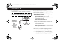
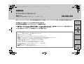
This option board provides simultaneous delivery of video in the JPEG and H.264 formats and also bi-directional video and
voice communications between the camera and PC.
■ Applicable models: Power Board Unit VA-84SA or VA-80SA
■ Cautions on Connecting Microphone/Speakers for Bi-directional Voice Communication
● Howling may occur if microphone and speakers are put too close. Move them apart or change the speakers orientation to
prevent howling. Also adjust the microphone sensitivity as well as the speaker volume.
● For speakers on the camera side, use speakers with built-in amplifier.
■ System Requirements
The system requirements for camera operation via network are as follows:
•PC: IBM PC/AT and compatibles
•OS: Windows XP Home Edition/Windows XP Professional
•CPU: Pentium IV (2.0GHz or higher) (3.0 GHz or higher for using the VA-SW3050Lite)
• Memory: 512MB or more (1 GB or more for using the VA-SW3050)
• Network interface: 10Base-T/100Base-TX (RJ-45 connector)
• Graphics processor: nVIDIA: GeForce 6000 series or higher
ATI: RADEON X1000 series or higher
• Display card: 1024 x 768 pixels or higher, 16 million colors or higher
• Web browser: Internet Explorer Ver.6.0 or higher
•Voice: Sound card and speakers with 100% DirectX compatibility
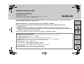
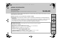
INSTALLATION MANUAL
Option Board (Network)
About this manual
Please read this installation manual before installing this unit, and always follow the instructions in it for proper use.
VA-82LAN
English Deutsch Français Español
中文简体
L9EBH_WA(VA-82LAN_INSTALLATION).book 1 ページ 2007年7月30日 月曜日 午後5時31分

2
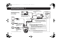
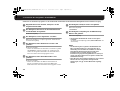
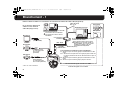
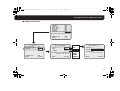
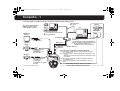
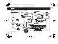
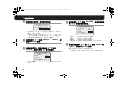
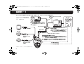
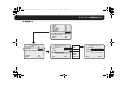
Connection - 1
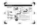
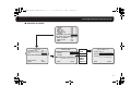
Connect the camera to the LAN through a switching hub using LAN cables (straight type).
✱4
✱5
✱1
✱2
✱3
Switching hub
PC
Speaker
Microphone
LAN cable (straight type)
Max. 100 m
LAN cable (straight type)
Voice signal transmission to camera
Voice signal check at PC
Video output
(BNC connector)
Voice output (black)
3.5 φ mini jack
(supplied with the
option board)
External microphone
input (white)
3.5 φ mini jack
(supplied with the option
board)
Microphone
Speaker
TV monitor
Video/voice data
Max. 100 m
When directly connecting
the camera to a PC, use the
LAN cable (cross type).
To prevent electromagnetic interference:
✱
1: Attach the white square clamping core (large) by winding the cable around
it twice.
✱
2, 3: Attach the two black round clamping cores (small) by nipping the cables
with them.
(Both cores need to be attached to the cables inside the camera body.)
✱
4: Attach the white round clamping core (large) by winding the cable around
it twice.
✱
5: Attach the white round clamping core (small) by nipping the cable with it.
* Use shielded LAN cables.
When using the IE/VA-SW3050Lite/VA-SW3050
server version:
You need the VA-SW3050 client version to
view live/replayed video, because the
VA-SW3050 server version is used for
recording purpose only.
When using the IE/VA-SW3050Lite/
VA-SW3050 client version:
You need a PC for the VA-SW3050
server version.
L9EBH_WA(VA-82LAN_INSTALLATION).book 2 ページ 2007年7月30日 月曜日 午後5時31分

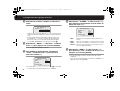
3
Connection - 1
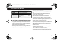
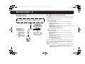
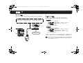
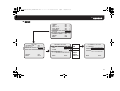
■ Internet connection
Connect the camera to a router or ADSL modem with LAN interface
using LAN cables.
■ About the internet connection
Port forwarding must be set on two of the router ports (camera side).
For details on how to set port forwarding, please refer to your router's
instruction manual.
• Video port number
Conduct the following port forwarding settings with respect to the
router:
IP address on the LAN side: Camera IP address (default:
192.168.0.2)
Port number on the LAN side: Camera video port number
(default: 80)
Port number on the WAN side: Optional
For communication, use TCP/IP.
• Voice port number
Conduct the following port forwarding settings with respect to the
router:
IP address on the LAN side: Camera IP address (default:
192.168.0.2)
Port number on the LAN side: Camera voice port number
(default: 34341)
Port number on the WAN side: Camera voice port number
(default: 34341)
For communication, use UDP.
When installing multiple cameras on the LAN side, change the voice port
number for the second camera onwards accordingly (default: 34341),
and make the port forwarding setting for the corresponding router.
When connecting to a router, use the straight type LAN cable.
When connecting to an ADSL modem or other devices, refer to the
instruction manual for the device.
✱1
✱2
Router or
ADSL modem
Internet
To prevent
electromagnetic
interference:
✱
1:
Attach the white
round clamping core
(large) by winding
the cable around it
twice.
✱
2:
Attach the white
round clamping core
(small) by nipping
the cable with it.
MEMO: When viewing video in H.264 format over the Internet, set the
communication protocol of H.264 to "HTTP". (See page 27 of
the INSTRUCTION MANUAL [VA-82LAN] contained in the
supplied CD-ROM.)
L9EBH_WA(VA-82LAN_INSTALLATION).book 3 ページ 2007年7月30日 月曜日 午後5時31分

4
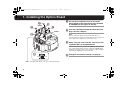
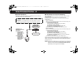
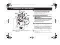
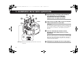
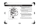
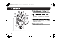
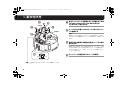
1. Installing the Option Board
1
Use the three supplied screws to install the
option board on the power board unit (VA-84SA
or VA-80SA)(see the figure on the left).
2
Pass the LAN cable through the cable hole and
plug it into the LAN port.
Note:
When it is difficult to plug in or pull out the LAN cable, we
recommend that you either use a LAN cable that has no plug cover
at the cable end, or displace the cover if there is one.
3
When using the voice interface, connect the two
supplied cables to the option board.
Connect the red connector cable to the CN805 (red) terminal for
voice output and the white connector cable to the CN806 (white)
terminal for microphone input. These connector cables should be
fixed firmly by wrapping once around the fixer.
4
Configure the network settings (see page 5).
CN806
CN805
1
1
1
2
3
3
A
Note: Arrange the two cables so as not to contact the board A.
L9EBH_WA(VA-82LAN_INSTALLATION).book 4 ページ 2007年7月30日 月曜日 午後5時31分

5
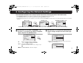
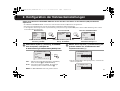
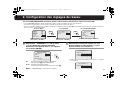
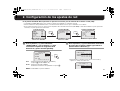
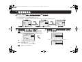
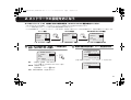
2. Configuring the Network Settings
On the NETWORK SETTING screen, specify the options required for connecting the camera to the network (LAN).
• The NETWORK SETTING screen appears only when the camera is equipped with this option board.
• For displaying the menu screen, refer to the instruction manual supplied with the camera.
• In the following instructions, the lever operations of the system controller (VSP-9000) are shown using xy for vertical operation and vw for horizontal
operation.
1
Use the lever (xy) to select “IP ADDRESS”, use
the lever (vw) to select the IP address assignment
option, and press the [ENTER] button.
2
Use the lever (xy) to select the setting item you
want to change, and press the lever to the right
(vw).
ROnly the selected option is displayed on the screen, and “x”
appears below the address.
CAMERA
LENS
PAN/TILT
AUTO MODE
PASSWORD
LANGUAGE
OPTION
ADVANCED MENU
SET
SET
SET
SET
SET
SET
SET
SET
y
y
y
y
y
y
y
y
ENTER
y
y
OPTION
INFORMATION
AUTO FLIP
NETWORK
SET
OFF
SET
ENTER
NETWORK SETTING
IP ADDRESS
PORT
ALARM
MAC ADDRESS
08-00-7I-81-25-J2
FIX
00080
OUT1/2
y
Menu screen
Use the lever (xy) to select “OPTION”.
OPTION screen NETWORK SETTING screen
Use the lever (xy) to select “NETWORK”. Perform the network settings.
FIX : Manual assignment (default: 192.168.0.2)
Go to step
2 (IP ADDRESS SETTING).
AUTO
Automatic assignment (DHCP)
Confirm the information in the screen, and go to step
4.
MEMO: The “MAC ADDRESS” cannot be changed.
NETWORK SETTING
IP ADDRESS
PORT
ALARM
MAC ADDRESS
08-00-7I-81-25-J2
FIX
00080
OUT1/2
y
ENTER
R
IP ADDRESS SETTING
IP ADDRESS
192.168.000.002
SUBNETMASK
255.255.255.000
GATEWAY
192.168.000.001
IP ADDRESS SETTING
IP ADDRESS
192.168.000.002
x
L9EBH_WA(VA-82LAN_INSTALLATION).book 5 ページ 2007年7月30日 月曜日 午後5時31分

6
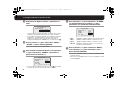
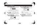
2. Configuring the Network Settings
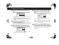
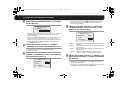
3
Select the digit to be changed, and specify the
value.
• Use the lever (vw) to move “x” to the digit you want to change,
and use the lever (vw) to select the number.
• If you change the setting item, use the lever vw) to move “x” to
either end, and press the lever (vw) toward the same end. This
displays the IP ADDRESS SETTING screen, returning you to
step
2.
4
Use the lever (xy) to select “MENU” – “BACK”,
and press the [ENTER] button.
RReturns to the NETWORK SETTING screen.
5
To change the port number, use the lever (xy) to
select “PORT”, and press the lever to the right (w).
RUse the same procedure as step 3 to change the port number
to your desired value (between 1 and 65535).
6
Use the lever (xy) to select “ALARM” and then
use the lever (vw) to select the alarm output
option.
•OFF: Disables alarm output from the camera to the
network.
•OUT1: Enables alarm output 1 to be sent to the network.
•OUT2: Enables alarm output 2 to be sent to the network.
• OUT1/2: Enables alarm outputs 1 and 2 to be sent to the
network (default setting).
7
Use the lever (xy) to select “MENU”, use the
lever (vw) to select “END”, and press [ENTER].
RCloses the settings screen and returns to the normal monitoring
screen.
• To return to the previous screen, select “BACK” and press the
[ENTER] button.
IP ADDRESS SETTING
IP ADDRESS
192.168.000.052
x
NETWORK SETTING
IP ADDRESS
PORT
ALARM
MAC ADDRESS
08-00-7I-81-25-J2
FIX
00080
x
OUT1/2
y
NETWORK SETTING
IP ADDRESS
PORT
ALARM
MAC ADDRESS
08-00-7I-81-25-J2
FIX
00090
OUT1/2
y
L9EBH_WA(VA-82LAN_INSTALLATION).book 6 ページ 2007年7月30日 月曜日 午後5時31分

7
2. Configuring the Network Settings
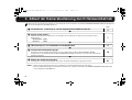
■ Screen Sequence
IP ADDRESS SETTING
IP ADDRESS
192.168.000.002
SUBNETMASK
255.255.255.000
GATEWAY
192.168.000.001
MENU BACK
NETWORK SETTING
IP ADDRESS
PORT
ALARM
MAC ADDRESS
08-00-7I-81-25-J2
MENU
FIX
00080
OUT1/2
BACK
y
CAMERA
LENS
PAN/TILT
AUTO MODE
PASSWORD
LANGUAGE
OPTION
ADVANCED MENU
PRESET
MENU
SET
SET
SET
SET
SET
SET
SET
SET
OFF
END
y
y
y
y
y
y
y
y
y
y
OPTION
INFORMATION
AUTO FLIP
NETWORK
PRESET
MENU
SET
OFF
SET
OFF
BACK
AUTO
FIX
OFF
OUT1
OUT2
OUT1/2
1-65535
L9EBH_WA(VA-82LAN_INSTALLATION).book 7 ページ 2007年7月30日 月曜日 午後5時31分

8
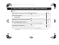
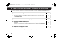
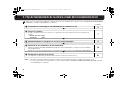
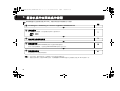
3. Flow of Camera Operation through to Network Operation
Perform the following procedures according to the detailed instructions given in the INSTRUCTION MANUAL [VA-82LAN] contained in the supplied
CD-ROM.
Refer to
1 Installing the “H.264 Plug-in” from the supplied CD-ROM onto PC
3
5
2 Accessing the Camera
Enter your user name and password, and then select a language you want to display on the screen.
User name: admin
Password: admin
7
5
3 Monitoring The Live Video In The Main Screen
9
5
4 Selecting the Operating Conditions
Using the [MAIN SETTINGS] screen for an administrative user, configure the detailed settings for administration.
When you access the camera for the first time, be sure to perform the settings on the [CLOCK SETTINGS] screen.
15
5
5 Changing the Camera Settings
Changes in the camera settings can be made through the network connection.
41
MEMO: • After you turn on the power, wait approximately one minute before network connection is established.
• When the TCP/IP settings on your PC are required, refer to page 5 of the INSTRUCTION MANUAL [VA-82LAN] contained in the
supplied CD-ROM.
L9EBH_WA(VA-82LAN_INSTALLATION).book 8 ページ 2007年7月30日 月曜日 午後5時31分

9
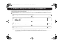
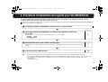
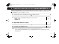
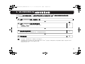
4. Software Setup Procedure for VA-SW3050Lite
The VA-SW3050Lite software achieves multiple monitoring by using up to 128 cameras and allows you to switch the monitoring screen
between single, 4-part split and 16-part split viewing.
Perform the following procedures according to the detailed instructions given in the INSTRUCTION MANUAL [VA-SW3050Lite] contained in the
supplied CD-ROM.
1 Installing the VA-SW3050Lite Software (see next page)
5
Refer to
2 Starting and Logging in to the VA-SW3050Lite Software
Double-click the “Network Recorder” shortcut icon created on the desktop.
USER ID: admin
PASSWORD: admin
5
5
3 Registering the Cameras with the Software
Register the camera(s) to access, and configure the camera settings such as IP address and camera title.
7
5
4 Viewing the Live Video
11
MEMO: • After you turn on the power, wait approximately one minute before you can login.
• To view the INSTRUCTION MANUAL contained in the supplied CD-ROM, you need Adobe
®
Reader
®
application. If your PC has not
been installed with it, you can download it for installation from the following web site at Adobe Systems Incorporated.
http://www.adobe.com
L9EBH_WA(VA-82LAN_INSTALLATION).book 9 ページ 2007年7月30日 月曜日 午後5時31分

10
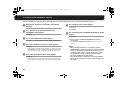
4. Installing the VA-SW3050Lite Software
Start the installation program from the software CD, and use the interactive dialog boxes to advance the installation process.
1
Double-click “Setup.exe” contained in the supplied
CD-ROM.
2
The “Welcome to the InstallShield Wizard for
VA-SW3050” dialog appears.
Click [Next].
3
The “License Agreement” dialog appears.
Select the “I accept the agreement” option and then click [Next].
4
The “Select Destination Location” dialog appears.
Click [Next].
• To change the destination folder in which you want to save the
VA-SW3050Lite software, click [Browse] and select the desired
folder. You may also type the folder name directly in the box.
5
The “Select Start Menu Folder” dialog appears.
Click [Next].
• To change the start menu folder, click [Browse] and select the
desired folder. You may also type the folder name directly in the
box.
6
The “Ready to Install” dialog appears.
Click [Install].
☞ Installing
7
The “Completing the VA-SW3050 Setup Wizard” dialog
appears.
Click [Finish].
☞ Now you have installed the VA-SW3050Lite software
successfully.
You will find the “Network Recorder” short cut icon on the
desktop.
MEMO:
• Microsoft .NET Framework 1.1 is required to use the
VA-SW3050Lite software. If your PC has not been installed
with it, an automatic installation program will show you a
confirmation dialog box to start its setup process, when
you double-click “Setup”. It will be about two minutes
before the installation program finishes.
• Once the installation is finished, you may be prompted to
restart the PC. Follow the instructions that may appear on
the screen.
L9EBH_WA(VA-82LAN_INSTALLATION).book 10 ページ 2007年7月30日 月曜日 午後5時31分

11
Specifications
Appearance and specifications are subject to change without prior notice
or obligations.
■ License for Software Contained in CD-ROM
• Please read carefully the terms and conditions contained in the
license agreement that appears on the screen during the software
installation process. Provided that you have agreed to all the terms
and conditions therein, you may use the software subject to the
license agreement.
• For information on the other products or services provided by third
parties which are introduced in the CD-ROM, please contact each
supplier or manufacturer.
■ Copyright notice
This instruction manual is copyrighted by SANYO Electric Co., Ltd.
No materials contained in this manual may be reproduced in any format
without the prior permission of the copyright holder.
Microsoft, Windows and Internet Explorer are registered trademarks or
trademarks of Microsoft Corporation in the United States and other
countries.
The official name for “Windows” used in this manual is Microsoft
®
Windows
®
Operating System. In this manual, note that the word
“Windows” refers to both “Microsoft
®
Windows
®
2000 Operating System”
and “Microsoft
®
Windows
®
XP Operating System”.
Intel and Pentium are registered trademarks or trademarks of Intel
Corporation and its subsidiaries in the United States and other countries.
IBM and IBM PC/AT are trademarks of International Business Machines
Corporation.
Adobe Reader is a trademark of Adobe Systems Incorporated.
UPnP is a trademark of UPnP Implementers Corporation, which is
established by the UPnP Forum SC.
Java is a trademark of Sun Microsystems, Inc.
All other brands and product names in this manual are the registered
trademarks or trademarks of their respective owners.
Power
consumption
21 W (for AC 24 V), 22 W (for AC 230 V)
When installed on the main unit
Power source Supplied from main unit
Weight Approx. 33 g (1.2 oz)
Accessory
Screw................................................................... 3
Cable with 3.5 φ mini jack
(black and white)......................................... each 1
Clamping core...................................................... 5
CD-ROM (VA-SW3050Lite).................................. 1
L9EBH_WA(VA-82LAN_INSTALLATION).book 11 ページ 2007年7月30日 月曜日 午後5時31分

L9EBH_WA(VA-82LAN_INSTALLATION).book 12 ページ 2007年7月30日 月曜日 午後5時31分

English Deutsch Français Español
中文简体
日本語
Diese Optionskarte ermöglicht gleichzeitig die Bildwiedergabe in den Formaten JPEG und H.264 und zudem die bidirektionale
Bild- und Sprachkommunikation zwischen Kamera und PC.
■ Modelle: Stromversorgungsmodul VA-84SA oder VA-80SA
■ Vorsichtsmaßnahmen für den Anschluss von Mikrofon/Lautsprechern für die bidirektionale
Sprachkommunikation
● Wenn der Abstand zwischen Mikrofon und Lautsprecher zu klein ist, können Misstöne (Heulen) entstehen. Vergrößern Sie
den Abstand oder verändern Sie die Ausrichtung der Lautsprecher, um Heulgeräuschen vorzubeugen. Darüber hinaus
empfiehlt es sich, die Empfindlichkeit des Mikrofons und die Lautstärke der Lautsprecher zu regulieren.
● Verwenden Sie Geräte mit eingebautem Verstärker für die Lautsprecher auf der Kameraseite.
■ Systemanforderungen
Die Systemvoraussetzungen für den Kamerabetrieb über das Netzwerk sind wie folgt:
•PC: IBM PC/AT und kompatible Modelle
• Betriebssystem: /Windows XP Home Edition/Windows XP Professional
•CPU: Pentium IV (2,0 GHz oder höher) (Mindestens 3,0 GHz bei Verwendung des VA-SW3050Lite)
• Arbeitsspeicher: mindestens 512 MB (Mindestens 1 GB bei Verwendung des VA-SW3050)
• Netzwerk-Schnittstelle: 10Base-T/100Base-TX (RJ45-Steckverbinder)
•Grafikchip: nVIDIA: GeForce 6000 oder höher
ATI: RADEON X1000 oder höher
• Grafikkarte: Mindestens 1024 x 768 Bildpunkte, Mindestens 16 Millionen Farben
• Internet-Browser: Internet Explorer Version 6.0 oder höher
• Sprachausgabe: Soundkarte und Lautsprecher mit 100% DirectX-Kompatibilität
INSTALLATIONSANLEITUNG
Optionskarte (Netzwerk)
Zu dieser Anleitung
Lesen Sie bitte diese Anleitung vor der Installation dieser Einheit sorgfältig durch
und befolgen Sie die Anweisungen für den richtigen Gebrauch.
VA-82LAN
L9EBH_WA(VA-82LAN_INSTALLATION).book 1 ページ 2007年7月30日 月曜日 午後5時31分

2
Anschlussschema - 1
Schließen Sie die Kamera über ein Umschalt-Hub mit LAN-Kabeln (Patchkabeln) an das LAN-Netzwerk an.
✱4
✱5
✱1
✱2
✱3
Umschalt-Hub
PC
Lautsprecher
Mikrofon
LAN-Netzwerkkabel (Patchkabel)
Max. 100 m
LAN-Netzwerkkabel (Patchkabel)
Sprachsignalübertragung an Kamera
Sprachsignalüberprüfung am PC
Video-Ausgang
(BNC-Stecker)
Sprach-Ausgang (schwarz)
3,5 φ Miniklinkenbuchse
(mit der Optionskarte
geliefert)
Externer Mikrofon-
Eingang (weiß)
3,5 φ Miniklinkenbuchse
(mit der Optionskarte
geliefert)
Mikrofon
Lautsprecher
TV-Monitor
Video-/
Sprachdaten
Max. 100 m
* Geschirmte LAN-Netzwerkkabel verwenden.
Zum direkten Anschluss der
Kamera an einen PC verwenden
Sie das LAN-Kabel
(Crossover-Kabel).
Vermeiden von elektromagnetischen Störungen:
✱
1: Bringen Sie den weißen quadratischen Ferritkern (groß) an, indem Sie
das Kabel zweimal darum wickeln.
✱
2, 3: Bringen Sie die zwei schwarzen runden Ferritkerne (klein) an, indem
Sie das Kabel mit diesen einklemmen. (Beide Ferritkerne müssen im
Kameragehäuse an das Kabel angebracht werden.)
✱
4: Bringen Sie den weißen runden Ferritkern (groß) an, indem Sie das Kabel
zweimal darum wickeln.
✱
5: Bringen Sie den weißen runden Ferritkern (klein) an, indem Sie das Kabel
mit diesem einklemmen.
Bei Verwendung der Version IE/VA-SW3050Lite/
VA-SW3050 Server:
Für das Betrachten von Live-Videobildern bzw. die
Videowiedergabe benötigen Sie die Version
VA-SW3050 Client, da die Version VA-SW3050
Server nur zu Aufnahmezwecken verwendet wird.
Bei Verwendung der Version IE/
VA-SW3050Lite/VA-SW3050 Client:
Für die Version VA-SW3050 Server
benötigen Sie einen PC.
L9EBH_WA(VA-82LAN_INSTALLATION).book 2 ページ 2007年7月30日 月曜日 午後5時31分

3
Anschlussschema - 2
■ Internet-Anschluss
Verbinden Sie die Kamera mithilfe von LAN-Kabeln mit einem Router
oder ADSL-Modem mit LAN-Schnittstelle.
■ Informationen zur Internet-Verbindung
Die Port-Weiterleitung muss auf zwei Ports des Routers (Kamera-Seite)
eingestellt werden.
Für Einzelheiten über die Vorgehensweise zur Einstellung der
Port-Weiterleitung, schlagen Sie bitte in der Bedienungsanleitung des
Routers nach.
• Video-Port-Nummer
Führen Sie die folgenden Einstellungen für die Port-Weiterleitung unter
Berücksichtigung des Routers aus:
IP-Adresse auf der LAN-Seite:
Kamera-IP-Adresse (Grundeinstellung: 192.168.0.2)
Port-Nummer auf der LAN-Seite:
Kamera-Video-Port-Nummer (Grundeinstellung: 80)
Port-Nummer auf der WAN-Seite: Optional
Verwenden Sie für die Kommunikation das TCP/IP-Protokoll.
• Voice-Port-Nummer
Führen Sie die folgenden Einstellungen für die Port-Weiterleitung unter
Berücksichtigung des Routers aus:
IP-Adresse auf der LAN-Seite:
Kamera-IP-Adresse (Grundeinstellung: 192.168.0.2)
Port-Nummer auf der LAN-Seite:
Kamera-Voice-Port-Nummer (Grundeinstellung: 34341)
Port-Nummer auf der WAN-Seite: Kamera-Voice-Port-Nummer
(Grundeinstellung: 34341)
Verwenden Sie für die Kommunikation das UDP-Protokoll.
Ändern Sie bei Installation mehrerer Kameras auf der LAN-Seite die
Voice-Port-Nummer ab der zweiten Kamera entsprechend (Grundeinstellung:
34341) und nehmen Sie die Einstellung für die Port-Weiterleitung für den
jeweiligen Router vor.
Verwenden Sie Patch-Netzwerkkabel, wenn Sie einen Router
anschließen.
Bei Anschluss an ein ADSL-Modem oder andere Geräte, wird auf
die Bedienungsanleitung des angeschlossenen Geräts verwiesen.
✱1
✱2
Router oder
ADSL-Modem
Internet
Vermeiden von
elektromagnetischen
Störungen:
✱
1:
Bringen Sie den
weißen runden
Ferritkern (groß) an,
indem Sie das
Kabel zweimal
darum wickeln.
✱2: Bringen Sie den
weißen runden
Ferritkern (klein) an,
indem Sie das
Kabel mit diesem
einklemmen.
MEMO: Stellen Sie zum Betrachten von Videobildern im Format H.264
über das Internet das Kommunikationsprotokoll für H.264 auf
„HTTP“ ein. (Siehe Seite 27 der BEDIENUNGSANLEITUNG
[VA-82LAN] auf der mitgelieferten CD-ROM.)
L9EBH_WA(VA-82LAN_INSTALLATION).book 3 ページ 2007年7月30日 月曜日 午後5時31分

4
1. Installieren der Optionskarte
1
Verwenden Sie die drei mitgelieferten Schrauben
zum Installieren der Optionskarte auf dem
Stromversorgungsmodul (VA-84SA oder
VA-80SA) (siehe Abb. links).
2
Führen Sie das LAN-Kabel durch die
Kabeldurchführung und stecken Sie es in den
LAN-Anschluss ein.
Hinweis:
Lässt sich das LAN-Kabel nur schwer einstecken oder abziehen,
empfehlen wir, entweder ein LAN-Kabel ohne Steckerabdeckung
am Kabelende zu verwenden oder die ggf. vorhandene
Abdeckung beiseite zu schieben.
3
Bei Verwendung der Sprachschnittstelle die zwei
mitgelieferten Kabel an die Optionskarte
anschließen.
Das Kabel mit dem roten Stecker an die Klemme CN805 (rot) für
die Sprachausgabe und das Kabel mit dem weißen Stecker an die
Klemme CN806 (weiß) für den Mikrofoneingang anschließen.
Diese Steckerkabel sollten zur sicheren Fixierung einmal um die
Befestigung gewickelt werden
4
Konfigurieren Sie die Netzwerkeinstellungen
(siehe Seite 5).
CN806
CN805
1
1
1
2
3
3
A
Hinweis: Ordnen Sie die zwei Kabel so an, dass diese die Karte A
nicht berühren.
L9EBH_WA(VA-82LAN_INSTALLATION).book 4 ページ 2007年7月30日 月曜日 午後5時31分

5
2. Konfiguration der Netzwerkeinstellungen
Geben Sie im Bildschirm NETZWERK EINST. die für den Anschluss der Kamera an das Netzwerk (LAN) erforderlichen
Optionen ein.
• Der Bildschirm NETZWERK EINST. erscheint nur, wenn die Kamera mit dieser Optionskarte ausgestattet ist.
• Zur Anzeige des Menübildschirms siehe die mit der Kamera mitgelieferte Bedienungsanleitung.
• In den folgenden Anweisungen wird die Joystick-Bedienung am Systemsteuergerät (VSP-9000) mit xy für die vertikale Bedienung und vw für die
horizontale Bedienung dargestellt.
1
Wählen Sie mit Joystick (
xy
) den Eintrag „IP-ADRESSE“,
dann mit Joystick (
vw
) die Option der
IP-Adresszuweisung und drücken Sie die [ENTER]-Taste.
2
Wählen Sie mit Joystick (xy) die Einstellung, die
geändert werden soll, und drücken Sie den
Joystick nach rechts (w).
RNur die gewählte Option wird angezeigt und „x“ wird unter der
Adresse eingeblendet.
KAMERA
OBJEKTIV
PAN/KIPP
AUTO-MODUS
KENNWORT
SPRACHE
OPTION
ERWEIT. MENUE
EINST
EINST
EINST
EINST
EINST
EINST
EINST
EINST
y
y
y
y
y
y
y
y
ENTER
y
y
OPTION
INFORMATION
AUTOM. UMDREH.
NETZWERK
EINST
AUS
EINST
ENTER
NETZWERK EINST.
IP-ADRESSE
PORT
ALARM
MAC-ADRESSE
08-00-7I-81-25-J2
FEST
00080
AL-1/2
y
Menübildschirm
Wählen Sie mit dem Joystick xy
den Eintrag „OPTION“.
Bildschirm OPTION Bildschirm NETZWERK EINST.
Wählen Sie mit dem Joystick xy den
Eintrag „NETZWERK“.
Nehmen Sie die
Netzwerkeinstellungen vor.
FEST : Manuelle Zuweisung (Grundeinstellung: 192.168.0.2).
Weiter mit Schritt
2 (IP-ADRESSE EINST.).
AUTO : Automatische Zuweisung (DHCP). Die angezeigte
Information prüfen und weiter mit Schritt
4.
MEMO: Die „MAC-ADRESSE“ kann nicht geändert werden.
NETZWERK EINST.
IP-ADRESSE
PORT
ALARM
MAC-ADRESSE
08-00-7I-81-25-J2
FEST
00080
AL-1/2
y
ENTER
R
IP-ADRESSE EINST.
IP-ADRESSE
192.168.000.002
SUBNETZMASKE
255.255.255.000
GATEWAY
192.168.000.001
IP-ADRESSE EINST.
IP-ADRESSE
192.168.000.002
x
L9EBH_WA(VA-82LAN_INSTALLATION).book 5 ページ 2007年7月30日 月曜日 午後5時31分

6
2. Konfiguration der Netzwerkeinstellungen
3
Wählen Sie die zu ändernde Ziffer aus und legen
Sie den Wert fest.
• Bewegen Sie mit dem Joystick (vw) das Zeichen „x“ auf die zu
ändernde Ziffer und wählen Sie mit dem Joystick (xy) die
gewünschte Zahl.
• Um zu einer anderen Einstelloption zu wechseln, bewegen Sie
mit dem Joystick (vw) das Zeichen „x“ an ein Ende und
drücken Sie den Joystick (vw) zum selben Ende hin. Hierdurch
wird der Bildschirm IP-ADRESSE EINST. angezeigt und zu
Schritt
2 zurückgekehrt.
4
Wählen Sie mit dem Joystick (xy) „MENUE“ –
„ZURUECK“ und drücken Sie die [ENTER]-Taste.
RDamit wird zum Bildschirm „NETZWERK EINST.“
zurückgeschaltet.
5
Zum Ändern der Port-Nummer wählen Sie mit dem
Joystick (xy) den Eintrag „PORT“ und drücken Sie
den Joystick nach rechts (w).
RVerwenden Sie das in Schritt 3 beschriebene Verfahren, um
die Port-Nummer auf den gewünschten Wert einzustellen
(zwischen 1 und 65535).
6
Wählen Sie mit dem Joystick (xy) den Eintrag
„ALARM“ und dann mit dem Joystick (vw) die
Option für den Alarmausgang.
•AUS: Deaktiviert den Alarmausgang von der Kamera zum
Netzwerk.
•AL-1: Aktiviert den Alarmausgang 1 zur Signalsendung an
das Netzwerk.
•AL-2: Aktiviert den Alarmausgang 2 zur Signalsendung an
das Netzwerk.
• AL-1/2: Aktiviert die Alarmausgänge 1 und 2 zur Signal-
sendung an das Netzwerk (Grundeinstellung).
7
Wählen Sie mit dem Joystick (xy) „MENUE“ und
dann mit dem Joystick (vw) „ENDE“ und drücken
Sie [ENTER].
R Schließt den Einstellbildschirm und schaltet zum normalen
Monitorbildschirm zurück.
• Um in den vorherigen Bildschirm zurückzukehren, wählen Sie
„ZURUECK“ und drücken Sie die [ENTER]-Taste.
IP-ADRESSE EINST.
IP-ADRESSE
192.168.000.052
x
NETZWERK EINST.
IP-ADRESSE
PORT
ALARM
MAC-ADRESSE
08-00-7I-81-25-J2
FEST
00080
x
AL-1/2
y
NETZWERK EINST.
IP-ADRESSE
PORT
ALARM
MAC-ADRESSE
08-00-7I-81-25-J2
FEST
00090
AL-1/2
y
L9EBH_WA(VA-82LAN_INSTALLATION).book 6 ページ 2007年7月30日 月曜日 午後5時31分

7
2. Konfiguration der Netzwerkeinstellungen
■ Menüfolge
IP-ADRESSE EINST.
IP-ADRESSE
192.168.000.002
SUBNETZMASKE
255.255.255.000
GATEWAY
192.168.000.001
MENUE ZURUECK
NETZWERK EINST.
IP-ADRESSE
PORT
ALARM
MAC-ADRESSE
08-00-7I-81-25-J2
MENUE
FEST
00080
AL-1/2
ZURUECK
y
KAMERA
OBJEKTIV
PAN/KIPP
AUTO-MODUS
KENNWORT
SPRACHE
OPTION
ERWEIT. MENUE
VOREINST.
MENUE
EINST
EINST
EINST
EINST
EINST
EINST
EINST
EINST
AUS
ENDE
y
y
y
y
y
y
y
y
y
y
OPTION
INFORMATION
AUTOM. UMDREH.
NETZWERK
VOREINST.
MENUE
EINST
AUS
EINST
AUS
ZURUECK
AUTO
FEST
AUS
AL-1
AL-2
AL-1/2
1-65535
L9EBH_WA(VA-82LAN_INSTALLATION).book 7 ページ 2007年7月30日 月曜日 午後5時31分

8
3. Ablauf der Kamerabedienung durch Netzwerkbetrieb
Gehen Sie wie im Folgenden beschrieben vor und schlagen Sie zu diesem Zweck in der detaillierten BEDIENUNGSANLEITUNG [VA-82LAN] nach,
die auf der mitgelieferten CD-ROM enthalten ist.
Siehe
1 Installation des „H.264 Plug-in“ von der mitgelieferten CD-ROM auf dem PC
3
5
2 Zugriff auf die Kamera
Geben Sie Benutzername und Kennwort ein und wählen Sie anschließend eine Sprache für die Anzeige auf dem
Bildschirm aus.
Benutzername: admin
Kennwort: admin
7
5
3 Überwachung des Live-Videobildes im Hauptbildschirm
9
5
4 Auswahl der Betriebsbedingungen
Konfigurieren Sie die detaillierten Einstellungen für einen Administrator im Menü [HAUPTEINSTELLUNGEN].
Vergessen Sie nicht, die Einstellungen im Menü [UHREINSTELLUNGEN] vorzunehmen, wenn Sie zum ersten Mal auf
die Kamera zugreifen.
15
5
5 Ändern der Kameraeinstellungen
Änderungen an den Kameraeinstellungen können über die Netzwerkverbindung vorgenommen werden.
41
MEMO: • Warten Sie nach dem Einschalten etwa eine Minute bis die Netzwerkverbindung hergestellt wurde.
• Wenn die TCP/IP-Einstellungen auf Ihrem PC erforderlich sind, schlagen Sie auf Seite 5 der BEDIENUNGSANLEITUNG [VA-82LAN]
auf der mitgelieferten CD-ROM nach.
L9EBH_WA(VA-82LAN_INSTALLATION).book 8 ページ 2007年7月30日 月曜日 午後5時31分
Page is loading ...
Page is loading ...
Page is loading ...
Page is loading ...
Page is loading ...
Page is loading ...
Page is loading ...
Page is loading ...
Page is loading ...
Page is loading ...
Page is loading ...
Page is loading ...
Page is loading ...
Page is loading ...
Page is loading ...
Page is loading ...
Page is loading ...
Page is loading ...
Page is loading ...
Page is loading ...
Page is loading ...
Page is loading ...
Page is loading ...
Page is loading ...
Page is loading ...
Page is loading ...
Page is loading ...
Page is loading ...
Page is loading ...
Page is loading ...
Page is loading ...
Page is loading ...
Page is loading ...
Page is loading ...
Page is loading ...
Page is loading ...
Page is loading ...
Page is loading ...
Page is loading ...
Page is loading ...
Page is loading ...
Page is loading ...
Page is loading ...
Page is loading ...
Page is loading ...
Page is loading ...
Page is loading ...
Page is loading ...
Page is loading ...
Page is loading ...
Page is loading ...
Page is loading ...
-
 1
1
-
 2
2
-
 3
3
-
 4
4
-
 5
5
-
 6
6
-
 7
7
-
 8
8
-
 9
9
-
 10
10
-
 11
11
-
 12
12
-
 13
13
-
 14
14
-
 15
15
-
 16
16
-
 17
17
-
 18
18
-
 19
19
-
 20
20
-
 21
21
-
 22
22
-
 23
23
-
 24
24
-
 25
25
-
 26
26
-
 27
27
-
 28
28
-
 29
29
-
 30
30
-
 31
31
-
 32
32
-
 33
33
-
 34
34
-
 35
35
-
 36
36
-
 37
37
-
 38
38
-
 39
39
-
 40
40
-
 41
41
-
 42
42
-
 43
43
-
 44
44
-
 45
45
-
 46
46
-
 47
47
-
 48
48
-
 49
49
-
 50
50
-
 51
51
-
 52
52
-
 53
53
-
 54
54
-
 55
55
-
 56
56
-
 57
57
-
 58
58
-
 59
59
-
 60
60
-
 61
61
-
 62
62
-
 63
63
-
 64
64
-
 65
65
-
 66
66
-
 67
67
-
 68
68
-
 69
69
-
 70
70
-
 71
71
-
 72
72


Sanyo VA-82LAN Installation guide
- Category
- Security cameras
- Type
- Installation guide
Ask a question and I''ll find the answer in the document
Finding information in a document is now easier with AI
in other languages
- français: Sanyo VA-82LAN Guide d'installation
- español: Sanyo VA-82LAN Guía de instalación
- Deutsch: Sanyo VA-82LAN Installationsanleitung
- 日本語: Sanyo VA-82LAN インストールガイド
Related papers
-
Sanyo VCC-HD4000 - Network Camera Quick Reference Manual
-
-
-
-
-
-
-
-
-
Other documents
-
 Golmar CAMARA IP EXTERIOR IPCAM/EXT Owner's manual
-
Marmitek IP Eye Anywhere 470 Owner's manual
-
Cudy M2100 Whole Home Mesh Wi-Fi System Installation guide
-
Cudy M1800 Installation guide
-
Huawei AX3000 User guide
-
Messoa NCR772 Quick start guide
-
Marmitek IP ROBOCAM 10 Owner's manual
-
-
Pentax IMAGE Transmitter 2 Owner's manual
-
