Page is loading ...

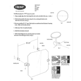
3000 LB. ROTISSERIE
INS TRUCTI ONS
Item #32194

2 Eastwood Technical Assistance: 800.343.9353 >> techelp@eastwood.com
The EASTWOOD ROTISSERIE is built using heavy gauge steel components mounted on six 4” swivel and locking casters to support up to a total loaded weight
of 3000lbs. [1360kg.] while offering shop mobility. Low-friction spindle design and fine-tuning height and balance adjustments provide greater safety and ease of
use. A generous 18’ [5.5m] maximum span will accommodate large vehicle bodies and projects.
CONTENTS
COMPONENTS
(2) Main Support Frame Assemblies - [A]
(4) Caster Arms - [B]
(6) Locking Swivel Casters - [C]
(2) Support Arm “Tee” Beams – [D]
(2) Spindle Support Assemblies - [E]
(2) Hydraulic Cylinders - [F]
(2) Hydraulic Cylinder Control Handles - [G]
(2) Spindle Assemblies - [H]
HARDWARE
• (24) M10 x 25mm Bolts, washers, lock washers and nuts
• (2) Cotter Pins
A
B
C
D
E
F
G
H
J
K
L
M
A
B
B
B
E
H
D
N
R
P
Hardware
(2) Spindle Assemblies - [H]
(2) Spindle Retaining Collar - [J]
(2) Spindle Rotating Bars - [K]
(4) Spindle Rotating Bar Grips - [L]
(2) Large Connector Beams - [M]
(2) Intermediate Connector Beams - [N]
(1) Small Connector Beam - [P]
(4) Attachment Arms - [R]

DANGER indicates a hazardous situation which, if not avoided, will result in death or serious injury.
WARNING indicates a hazardous situation which, if not avoided, could result in death or serious injury.
CAUTION used with the safety alert symbol, indicates a hazardous situation which, if not avoided, could result in minor or moderate injury.
NOTICE is used to address practices not related to personal injury.
READ INSTRUCTIONS
• Thoroughly read and understand this manual before using.
• Save for future reference.
SEVERE INJURY OR DEATH HAZARDS!
• DO NOT attempt to move Rotisserie on sloped surfaces while loaded.
• DO NOT concentrate a heavy load to either side or end of the Rotisserie. This can cause the balance to shift suddenly, tipping the
Rotisserie and its load which can quickly cause severe injury! Any uneven weight bias of the load MUST be known before attempting to
place it on the Rotisserie
• DO NOT exceed the rated 3000lb [1360kg.] (1500 lbs. [680kg.] per end) weight capacity.
• DO NOT use to support humans or animals.
• DO NOT climb on the Rotisserie.
• DO NOT use the Rotisserie to support items other than auto body shells, chassis, frames or pickup cabs.
• DO NOT attempt to transport this Rotisserie with a load attached by any hauling method.
• DO NOT remove or cover any of the factory supplied labels or warnings! They include specific safety information that must be
communicated to future users.
SAFETY INFORMATION
The following explanations are displayed in this manual, on the labeling, and on all other information provided with this product:
To order parts and supplies: 800.343.9353 >> eastwood.com 3
TOOLS REQUIRED
• Two 10mm wrenches
• Two 12mm wrenches
• Two 19mm wrenches
• Two 24mm wrenches
• One rubber mallet
SPECIFICATIONS
Max. Weight Capacity: 3000lb [1360kg.] (1500 lbs. [680kg.] per end)
Max. Extended Capacity: 18’ [5.5m] (Face to Face of “Tee” Beams [D])
Overall Spindle Height (Centerline of vehicle): 5’ [1.5m]
Overall Max. Extended Length: 22’ [6.7m]
Overall Extended Width: 70” [1.78m]

4 Eastwood Technical Assistance: 800.343.9353 >> techelp@eastwood.com
FALL HAZARD!
• Awkward, out of balance body positions may be attempted while trying to reach specific areas of objects placed on the Rotisserie dur-
ing use. Failure to ensure proper footing can quickly result in a fall which could inflict serious personal injury or property damage.
PINCH/CRUSH HAZARD!
• This Rotisserie has moveable components that can crush and pinch. Keep fingers and hands away from pinch points when operating.
SAFETY INFORMATION
ASSEMBLY PREPARATION
• Obtain the assistance of a helper during assembly. DO NOT attempt to construct this Rotisserie without assistance!
• The use of ANSI approved safety shoes, head protection gear and eye protection is necessary.
• Perform assembly in a large, uncluttered area close to area of intended use.
• Allow sufficient area for operator and helper to remain clear when choosing operating area.
• Use only on a firm, smooth, level and clean work surface.
DO NOT use on a sloped or rough textured surface, earth, grass, sand, gravel or any other loose surface.
• DO NOT attempt to move Rotisserie on sloped surfaces while loaded.
• DO NOT exceed the maximum length of 18’ [5.5m] (as measured between faces of the Support Arm “Tee” Beams).
INJURY HAZARDS!
The Eastwood Rotisserie consists of heavy metal components which can cause potentially serious injuries if allowed to drop.
Avoid pinching hands while handling parts during assembly.

To order parts and supplies: 800.343.9353 >> eastwood.com 5
ASSEMBLY
The two End Assemblies of the Rotisserie are mirror images of one another (Fig 1). All steps described for assembly will be
repeated for the opposite side.
To prevent scratches and damage to the finish of the Rotisserie components, it is strongly advisable to use cardboard, carpet,
blankets etc. covering a minimum 10’ x 10” area before beginning assembly.
CASTERS [C] AND CASTER ARMS [B] TO MAIN SUPPORT FRAME [A]
1. Place the Main Support Frame Assembly [A] with the Vertical Post
with Roller standing upward (FIG 1).
2. Attach a Locking Swivel Caster [C] to flange of Main Support
Assembly [A] using four M10 x 25mm Bolts, Washers, Lockwash-
ers and Nuts. Tighten securely using two 17mm wrenches (not
included) (FIG 2).
3. Attach Locking Swivel Casters [C] to flanges of Caster Arms [B]
using four M10 x 25mm Bolts, Washers, Lockwashers and Nuts
(FIG 3). Tighten securely using two 17mm wrenches
(not included).
4. Insert two assembled Caster Arms with Casters [B] & [C] into the
open tubes of the Main Support Frame [A] at the proper indicated
depth at 4” [10cm] from the ends (FIG 4) and tighten clamping
screws with a 19mm wrench (not included).
FIG. 1
A
FIG. 2
C
A
C
FIG. 3 FIG. 4
C
B
B
B
C
C
A

6 Eastwood Technical Assistance: 800.343.9353 >> techelp@eastwood.com
SUPPORT ARM “TEE” BEAM [D] TO SPINDLE [H]
1. Set the Support Arm “Tee” Beam [D] on the floor with the gussets
facing downward (FIG 5).
2. Remove the Lock Pin, Washer and Clip from the Support Arm
“Tee” Beam [D] and set aside for later replacement (FIG 5).
3. Slide the rectangular tube section of the Spindle Support Assembly
[H] over the post of the Support Arm “Tee” Beam [D] with the
Cylindrical Spindle facing upward (FIG 5).
4. Remove the M12 Locknut and 3 pieces of the Bearing from the end
of the Jackscrew and set aside for re-installation (FIG 6).
5. Insert the machined & M12 threaded end of the Jackscrew through
the holes in the Crossbeam of the Support Arm “Tee” [D] with the
M12 threads visible on the opposite side.
6. Reinstall the 3 pieces of the Bearing using care to install the
components in the proper direction and sequence (FIG 7). Secure
with the M12 Locknut and tighten in place with a 19mm wrench
(not Included) (FIG 8).
NOTE: Do Not overtighten or Bearings will bind). Insert Cotter Pin
through hole and bend in place.
7. Apply a liberal amount of high-quality synthetic, high-load
wheel bearing grease or an anti-seize compound to the
Bearings before use.
FIG. 5
FIG. 6
E
FIG. 7
FIG. 8
D

To order parts and supplies: 800.343.9353 >> eastwood.com 7
1. Using a 19mm wrench (not Included) remove Locknut, Washer and
Crank Handle from the upper end of the Jackscrew and set aside
for reinstallation (FIG 9).
2. Remove two M6 x 20 Screws, Washers & Locknuts in the Jack-
screw Guide Bracket with two 10mm wrenches (not included) and
set aside for reinstallation.
3. Secure the Jackscrew Guide Bracket to the Tab on the Post of the
Support Arm “Tee” Beam with the previously removed M6 x 20
Screws, Washers & Locknuts and secure with two 10mm wrenches
(not included) (FIG 10).
4. Replace the Crank Handle over the flats on the end of the
Jackscrew with the Handle upward and secure with the M12 Nut
and Washer. Tighten securely with a 19mm wrench (not included)
(FIG 11).
5. Turn the Crank as needed to raise or lower the Support Arm “Tee”
Beam [D] as needed to align the nearest of the 7 through holes with
the through hole in the Spindle Post [A] then insert the previously
removed Lock Pin, Washer and Clip.
6. At this point the assembly should appear as in FIG 12.
FIG. 9
FIG. 10
FIG. 11 FIG. 12

8 Eastwood Technical Assistance: 800.343.9353 >> techelp@eastwood.com
FIG. 13
FIG. 14
FIG. 16
FIG. 15
HYDRAULIC CYLINDER [F] TO MAIN SUPPORT FRAME ASSEMBLY [A]
1. Lock all Swivel Caster Brakes by pressing downward on the “ON” tab
of the Lock Pedal.
2. Remove the Lock Pin, Washer and Clip from the holes through the
through holes of the Main Support Frame Assembly [A] and set aside
for later replacement.
3. Remove the M16 x 90mm shoulder bolt, Locknut and Washer from
the mounting plates of the Main Support Frame Assembly [A] and set
aside for later replacement (FIG 13).
4. Set the lower clevis mount of a Hydraulic Cylinder [F] between the
mounting plates of the Main Support Frame Assembly [A] and locate
it with the previously removed M16 x 90mm shoulder bolt. Secure
it with the M16 locknut and washer and tighten with two 24mm
wrenches (not included) (FIG 14). NOTE: Do Not allow the Hydraulic
Cylinder [F] to fall forward.
SPINDLE SUPPORT ARM [E] TO MAIN SUPPORT FRAME ASSEMBLY [A]
AND HYDRAULIC CYLINDER [F].
1. Remove the M16 x 80mm Locknut and Washer from the cylinder
mounting plates at the underside of the Spindle Support [E] (FIG 15)
and set aside for reinstallation.
2. With the Latch Pin facing forward, slide the square tube post of the
Spindle Assembly [H] & [D] down into the larger square tube upright
of the Main Support Frame [A] (FIG 16).
3. Align the pivot hole in the Hydraulic Cylinder ram with the through
holes of the Spindle Support [E].
NOTE: The Hydraulic Cylinder may need to be extended or retracted to
allow the holes to align (FIG 16).
4. Insert the previously removed M16 x 80mm Shoulder Bolt through the
Hydraulic Cylinder ram and anchor plates then secure in place with
the M16 Locknut and Washer. Tighten with two 24mm wrenches (not
included).
5. Raise or lower the Hydraulic Cylinder ram as needed to align the
through hole of the Main Support Post [A] with the nearest of the
7 holes in the Spindle Support post [E] then insert the previously
removed Lock Pin, Washer and Clip.
E
A
F
✓
✓
✓

SPINDLE AND SUPPORT ARM “TEE” BEAM ASSEMBLY [H] & [D] TO
MAIN SUPPORT FRAME & SPINDLE SUPPORT ASSEMBLY [A] & [E].
1. Remove the Retaining Clip and Washer from the Spindle Latch Pin and
set aside for reinstallation.
2. Apply a liberal amount of high-quality synthetic, high-load wheel
bearing grease or an anti-seize compound to the bearing surfaces of
the Spindle Support and outside of the Spindle before insertion.
3. Lift the Spindle and “Tee” Beam Assembly [H] and [D] and insert the
Spindle into the Sleeve. Push it in fully engaging the Latch Pin with the
hole nearest the 12:00 position of the 10 in the Rotation Lock Plate
(FIG 17).
4. Reinstall the previously removed Retaining Clip and Washer onto the
Spindle Latch Pin (FIG 17).
5. Slide the Spindle Retaining Collar [J] over the protruding inboard end
of the Spindle [H] and align the through holes (FIG 18).
6. Insert the Spindle Rotating Bar [K] through the Spindle Retaining
Collar [J] and the Spindle [H] (FIG 19).
7. Push the rubber Spindle Rotating Bar Grips [L] fully onto the ends of
the Spindle Rotating Bar [K] (FIG 20).
8. The assembly should appear as in FIG 21. Repeat assembly procedure
for opposite end.
To order parts and supplies: 800.343.9353 >> eastwood.com 9
The assistance of a capable assistant is required for
the following step.
FIG. 17
FIG. 18
FIG. 19
FIG. 20
FIG. 21
E
✓
✓
✓
HJ
✓
K
L
✓

10 Eastwood Technical Assistance: 800.343.9353 >> techelp@eastwood.com
JOIN ROTISSERIE HALVES
Note once again that the two Rotisserie end assemblies are mirror images
of one another (FIG 22).
1. Arrange each Rotisserie half assembly on the floor with the open
beams facing another and resting solidly on their casters (FIG 22).
2. Slip the non-lockbolt end of each of the two Large Connector Beams
[M] into the two arms of the Rotisserie half assembly. Do Not allow
the Beam to extend beyond the minimum insertion lines marked at
4” [10cm] from the Beam end (FIG 23). Lightly tighten the Lockbolt
with a 21mm wrench (not included) to keep Beam from sliding.
3. Slide the non-lockbolt end of each of the two Intermediate Connec-
tor Beams [N] into the ends of the Large Connector Beams [M]. Do
Not allow the Beam to extend beyond the minimum insertion lines
marked at 4” [10cm] from the Beam end (FIG 24). Lightly tighten
the Lockbolt with a 21mm wrench (not included) to keep Beam from
sliding.
4. Slip the non-lockbolt end of each of the single Small Connector
Beam [P] into the ends of the Intermediate Connector Beams [N].
Do Not allow the Beam to extend beyond the minimum insertion lines
marked at 4” [10cm] from the Beam end (FIG 24). Lightly tighten
the Lockbolt with a 21mm wrench (not included) to keep Beam from
sliding.
5. Apply a liberal amount of high-quality synthetic, high-load wheel
bearing grease or an anti-seize compound to the Jackscrew acme
threads before use.
FIG. 22
FIG. 23
FIG. 24
Do Not allow any of the telescoping Beams [B], [M],
[N] & [P] to extend beyond the marked minimum
insertion lines or collapse can occur.
Maximum
Extension
✓
M
✓
✓
✓
✓
MN NP

ATTACHMENT ARMS [R] TO SUPPORT “TEE” BEAMS [D].
1. Slide the larger open square tube of the Attachment Arm over the
lesser square tube of the Support “Tee” Beam (FIG 25).
2. Once a method for attachment to vehicle body has been determined,
tighten the Lockbolts with a 21mm wrench (not included) (FIGS 26
& 27).
The Eastwood Rotisserie is now ready for use (FIG 28).
To order parts and supplies: 800.343.9353 >> eastwood.com 11
It is extremely important that the Attachment Arms
be set at an equal distance from the centerline of the
Support “Tee” Beam when mounting a vehicle body to
avoid a dangerous out of balance condition.
FIG. 25
FIG. 26
FIG. 28
FIG. 27
✓
R
✓
R

12 Eastwood Technical Assistance: 800.343.9353 >> techelp@eastwood.com
ROTISSERIE ADJUSTMENTS & SET-UP
• The assembled Rotisserie has limited adjustments for length as
well as Support Arm “Tee” Beams [D] height.
• First determine where the face of the Support Arm “Tee” Beams
[D] would be best located to safely support the subject project
car body and allow it to rotate without a dangerous top-heavy or
bottom-heavy bias.
• Always adjust the length to take advantage of the greater strength
in the Large and Intermediate Beams by minimizing the exposure
of the single center Small Beam [P]. Begin by telescoping the
Large Connector Beams [M] first, the Intermediate Connector
Beams [N] next and the Small Connector Beams [P], last.
• Always equalize the exposed amount of the Connector Beams
between both ends.
LENGTH ADJUSTMENT: (MAXIMUM 18’ [5.5M] FACE TO FACE
OF SUPPORT ARM “TEE” BEAMS [D] (FIG 29).
1. Loosen the Lockbolts on the Support Arm “Tee” Beams [D] then
carefully slide out the Large Connector Beams [M] exercising
extreme care not to exceed the minimum exposure depth. Lightly
tighten the Lockbolts.
2. Loosen the Lockbolts on the Large Connector Beams [M] then
then carefully slide out the Intermediate Connector Beams [N] ex-
ercising extreme care not to exceed the minimum exposure depth.
Lightly tighten the Lockbolts.
3. Loosen the Lockbolts on the Intermediate Connector Beams [N]
then carefully slide out the Small Connector Beam [P] exercising
extreme care not to exceed the minimum exposure depth. Lightly
tighten the Lockbolts.
4. Once all lengths are balanced side to side and adjustments final-
ized, tighten all Lockbolts with a 21mm wrench (not included).
It is strongly recommended that all telescoping Beam connections be tack welded as a safety measure before final use.
They can easily be ground away to support a different vehicle for future use (FIG 30).
FIG. 29
FIG. 30
18’ [5.5m] Maximum
✓
✓

ROTISSERIE USE
The number of vehicle variations and mounting possibilities among vehicles is nearly unlimited. The user must determine the strongest and safest method of
supporting the vehicle body and or chassis to the Rotisserie. Some general suggestions are listed below:
• Unitized body vehicles:
- Attach to suspension mounting points
- Attach to bumper mounting points
- Attach to engine or drivetrain mounting points
• Full-frame vehicles with body off frame:
- Attach to body mounts
• Full frame vehicles with body on frame:
- Attach to suspension mounting points
- Attach to bumper mounting points
• Subframe vehicles with subframes removed:
- Attach to suspension mounting points
- Attach to bumper mounting points
- Attach to subframe mounts
• Truck cabs removed from frame:
- Attach to body/cab mounts
• Truck cabs with cab on frame:
- Attach to suspension mounting points
- Attach to bumper mounting points
• Fiberglass body vehicles (Corvette, Avanti etc.):
- Attach body to specially constructed support frame or structure which is attached to Rotisserie
WIDTH ADJUSTMENT
- Support Arm “Tee” Beam [D] Initial Adjustments
1. Remove the Lock Pin, Washer and Clip from the Main Support Frame [A] and Spindle Support [E].
2. Using the Hydraulic Cylinders [F] move the Spindle up or down as required to place it in line with the balance centerline of the vehicle body.
3. Align the holes in Main Support Frame [A] with the nearest of 7 holes in Spindle Support [E] then replace the Lock Pin, Washer and Clip.
- Support Arm “Tee” Beam [D] Fine-Tuning Adjustments
1. Remove the Lock Pin, Washer and Clip from the Support Arm “Tee” Beam [D] and Spindle [H].
2. Using the Jackscrew Handle, thread the Jackscrew up or down as required to dial-in the precise centerline balance of the vehicle body.
3. Align the holes in the Spindle [H] with the nearest of 7 holes in Support Arm “Tee” Beam [D] then replace the Lock Pin, Washer and Clip.
To order parts and supplies: 800.343.9353 >> eastwood.com 13
In the interest of safety, the Caster Arms should ALWAYS be extended to the minimum exposure depth line when the Rotisserie
is in use. They should only be retracted when the Rotisserie is out of use and in storage.
Most vehicle bodies, especially convertibles, must first be braced to avoid distortion or bending of body in the door openings,
window openings and other areas. This is also critical in rust-damaged bodies to avoid body distortion, damage or collapse.

14 Eastwood Technical Assistance: 800.343.9353 >> techelp@eastwood.com
MOUNTING
1. The vehicle body should be supported on jack stands (not included), body cart or other suitable arrangement with the mounting points at 12” [3.6m] or
more above the floor.
2. Body must initially be positioned on Rotisserie in a bottom-heavy condition to prevent tipping when raised and avoid sudden rotation if Rotation Latch Pin
is retracted (keep Spindle centerline above the vehicle body weight balance centerline).
3. Begin raising the vehicle body with the Hydraulic Cylinders on both ends slowly at the same time while keeping it level.
4. Raise vehicle body to a height that will accommodate adequate clear-
ance between the side of the vehicle body and the lower structure of the
Rotisserie when rotated 90°. Place Lockpin & Clip into nearest through
holes of Main Support Post [A] and Spindle Support [E].
5. Keeping the spindle centerline above body weight balance center-
line, carefully remove Clips, Lockpins and Washers from the Spindle
Latch Pins and retract them against spring pressure. Reinsert pin into
retracted position hole (FIG 31).
6. At this point the vehicle body will react to a slight sideways push with a
pendulum-like rocking action.
7. Slowly and carefully rotate the Jackscrew Handcranks at the same time
to “fine-tune” and raise the vehicle body centerline nearer to the spindle
centerline.
8. Once the balance point is reached, reinstall the Lockpins, Clips and Washers into the Spindles [H] and Support Arm “Tee” Beams [D].
9. As the vehicle body is rotated into the desired position, remove Clips, Lockpins and Washers from the Spindle Latch Pins, release them form the retracted
position and lock into nearest Spindle Lock Plate hole. Replace Lockpins, Clips and Washers into the Spindle Latch Pins.
When mounting a vehicle body, the Eastwood Rotisserie should only be used on a flat, level and hard surface preferably indoors.
To help keep the Rotisserie free of sanding and grinding debris or paint overspray and maintain appearance, it is advisable to cover
or wrap the entire Rotisserie in plastic sheeting. This is particularly important to consider for protection of the moving mechanical
components of the Rotisserie.
Proceed slowly and carefully as shifting the balance point of the vehicle body to quickly can cause it to suddenly and violently flip
causing severe injury or death and severe damage.
Store the Rotisserie on a flat, level surface only to prevent possible unattended rolling and property damage.
Only release the Caster Locks when moving the Rotisserie. The Caster Locks MUST be applied whenever the Rotisserie is stationary.
FIG. 31
The aid of a capable assistant is required.
Retract Lock
Location
✓

To order parts and supplies: 800.343.9353 >> eastwood.com 15
MAINTENANCE
• Keep all moving components of the Rotisserie well lubricated and
free of and dirt or debris accumulations.
This includes (FIGS 32 & 33):
- Jack Screw Threads and Guide.
- Jack Screw Bearings (upper and lower).
- Jack Screw Upper Guide.
- Hydraulic Cylinder Pivots.
- Spindle Sleeve Bushings.
- Spindle Post Roller Bushings.
- Caster Zerk Fittings.
• The Rotisserie is finished in rugged powdercoating which will provide
many years of effort free beauty however it is advisable to keep the
finish clean and free from excessive dust and dirt.
• Keep the Rotisserie in a clean and dry environment.
DO NOT store it in or expose it to a damp or wet environment.
• Occasionally inspect all components for potential damage and proper
alignment. Check all hardware for tightness.
• DO NOT use if damage is discovered.
FIG. 32
FIG. 33
Lube
✓
Lube
✓
✓
Lube
✓
✓
✓
Lube
✓
Lube
Lube
✓
✓
Lube
✓
✓
Lube

© Copyright 2018 Easthill Group, Inc. 7/18 Instruction item #32194Q Rev 1
If you have any questions about the use of this product, please contact
The Eastwood Technical Assistance Service Department: 800.343.9353 >> email: techelp@eastwood.com
PDF version of this manual is available at eastwood.com
The Eastwood Company 263 Shoemaker Road, Pottstown, PA 19464, USA 800.343.9353 eastwood.com
/