Changing PCB
Upgrade Manual 281 - 00.0 - 09/2014
6
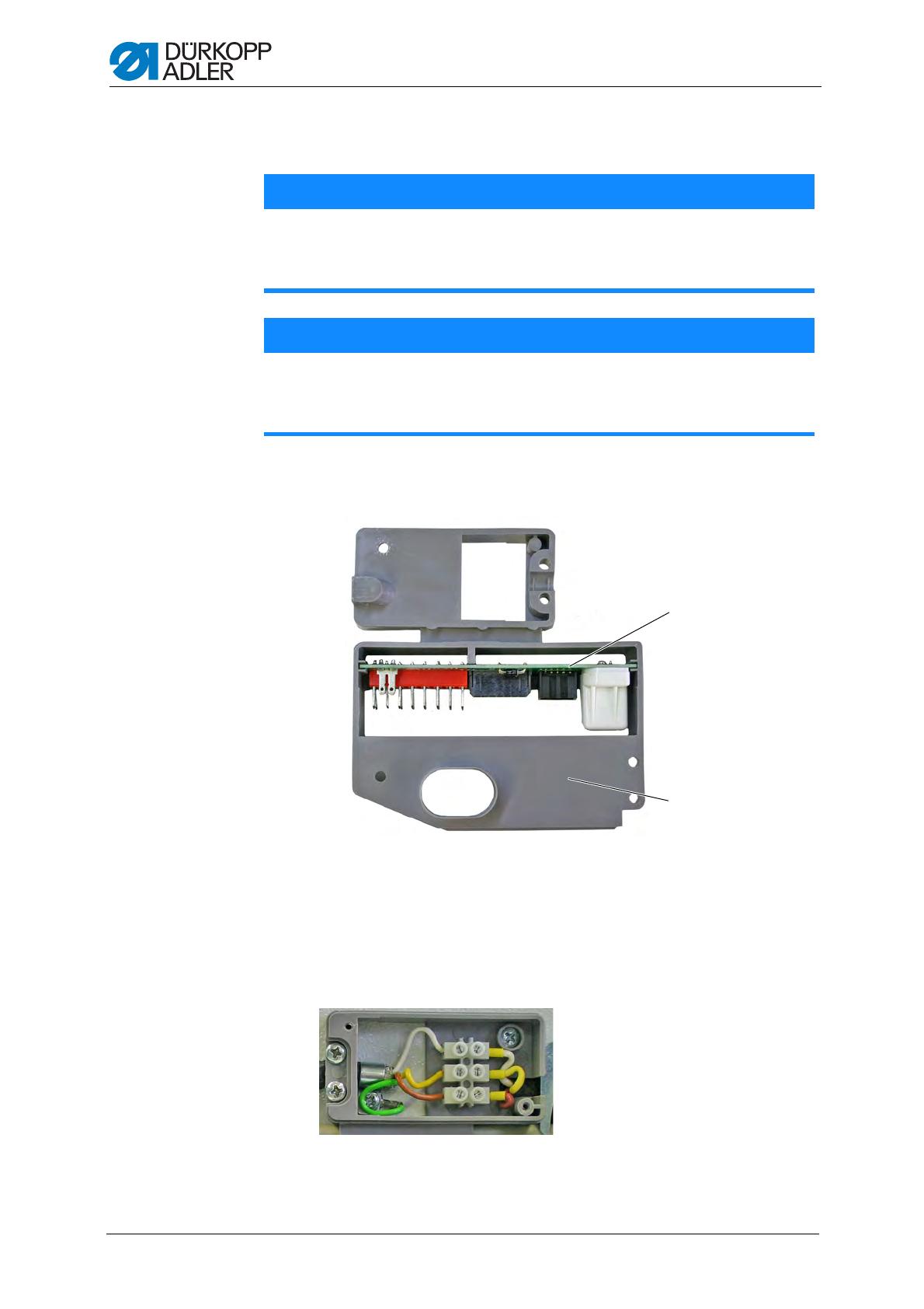
2.2 Installing new PCB
1. Push the new PCB (1) in the electrode holder (2) with the correct align-
ment.
Figure. 4: Positioning the new PCB in the electrode holder
2. Screw on the electrode holder (2) again.
3. Connect the plug in the low-voltage range in accordance with the circuit
diagram, 4 Appendix, page 9.
4. Connect the luster terminals in the high-voltage range according to iden-
tical colors.
Figure. 5: Connecting the luster terminals
5. Mount the high-voltage range cover again.
The new PCB is installed.
ATTENTION
Material damage due to forceful installation
Do not push the PCB into the electrode holder using force. Ensure that
the alignment is correct when installing the new PCB.
ATTENTION
Material damage due to crushing possible
Route the cables so that they have no contact with the rotating shaft.
Do not crush the cables when laying.
(1) - PCB (2) - Electrode holder
②
①


