Page is loading ...

1
2
3
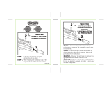
Determine mounting height and location of the Pool Latch
based upon state and local pool code requirements.
Project must meet local building codes before installation.
a.) Attach the saddle and one bracket together and
slide into the back of the Pool Latch. Keep bottom
of saddle ush with bottom of pool latch. Mount the
Pool Latch on the post at the determined height. With
a pencil, mark bottom of the saddle location (Fig. 1).
b.) Move upper bracket ¼" from the bottom of the
post cap and mark with a pencil the location of
the top bracket. NOTE: brackets can be ipped
when attaching to saddle for left or right handed
applications.
a.) Align the bottom of the saddle to the pencil mark.
NOTE: make sure the saddle and bottom bracket are
locked together.
b.) Pre-drill the three holes for the bottom bracket using
a
3
⁄32" drill bit and, using a screwdriver, secure the
bottom bracket to the post using three of the 1" at
head screws provided (Fig. 2).
c.) Keeping the saddle locked with the bottom bracket,
pre-drill the two center holes of the saddle using a
3
⁄32" drill bit and using a screwdriver, secure the
bottom bracket to the post using two of the 1" at
head screws provided. Repeat step b.) for the top
bracket using the pencil line for the height (Fig. 2).
a) Insert machine screw and retaining U-washer into
saddle. NOTE: machine screw should be inserted
vertically (Fig. 3).
b) Using the Phillips driver, turn machine screw while
keeping vertical and push down Pool Latch. Once
threads engage, lower the latch until the bottom of the
Pool Latch is aligned with the bottom of the saddle
(Fig. 4).
Using a Phillips drive, remove the two cover screws from
the back of the striker and remove the cover (Fig. 5).
a.) Place the striker on the gate, allowing the striker pin
to engage the latch.
b.) With a pencil, mark the location of the striker on the
gate (Fig. 6). NOTE: make sure the striker is level.
c.) While holding the striker in place, gently lift the Pool
Latch handle to release latch and open gate.
* Must be used with pool code approved self-closing hinges and installed at required height specied per local building code. Always refer to all local building codes prior to use.
QTY Description
1 Pool Latch
1 Striker
2 Brackets
2 Keys
1 Retaining U-Washer
1 Saddle
12 Square/Phillips Combo Flat Head Screws
4 Square/Phillips Combo Pan Head Screws
1 Machine Screw
WARNING:
• Improper installation of this product can result in
personal injury. Always wear safety goggles when
cutting, drilling and assembling the product.
• Incorrect installation may cause harm to the gate or
individual.
• Meets Pool Safety Code*
• DO NOT allow children to play with gate.
NOTICE:
• DO NOT attempt to assemble the kit if parts are
missing or damaged.
• DO NOT return the product to the store, for assistance
or replacement parts call: 1-800-336-2383.
Gate
Safety Glasses
Pencil
Drill
3
⁄32" Drill Bit
Phillips Drive
Square Drive (optional)
Tape Measure
TOOLS NEEDED:BEFORE YOU BEGIN:
When installing a gate on a fence, please note that vinyl gate
posts require an internal support system for weight-bearing
purposes and therefore wooden inserts or a post stiffener is
required. Post stiffener needs to be purchased separately.
Always consult your local building code department for
applicable regulations and product acceptance.
1
3D MODEL FILENAME
73024442
ESTIMATED WEIGHT: 0.18 lbs
REV
BY
DATE
PCR
DESCRIPTION
ITEM
PART No.
DESCRIPTION
QTY.
1
EPN-8094-12
MAGNETIC POOL LATCH (BLACK)
1
2 34107562
POOL SAFETY LATCH HARDWARE KIT - BLACK
1
3
EPN-6203
POOL LATCH KEY
2
4
EPN-2310
POOL LATCH LOCK PIN BASE SPACER
1
5
EPN-2305-12
POOL LATCH BRACKET (BLACK)
2
6
EPN-5641
POOL LATCH INSTRUCTION SHEET
1
7
EPN-5644
BOERBOEL BRANDED 8 MIL 2-SIDED 6-COLOR PRINTED POLYBAG w/ UPC
1
8
EPN-5647
POOL LATCH CARTON (LG)
1
9
EPN-4154
RETAINING U-WASHER
1
10
EPN-6178
M3.5 X 29.2mm PAN HEAD MACHINE SCREW, SS
1
THE INFORMATION CONTAINED IN THIS
DRAWING IS PROTECTED BY
COPYRIGHT AND PATENT LAWS OF THE
UNITED STATES AND OTHER
COUNTRIES. ANY REPRODUCTION IN
PART OR AS A WHOLE WITHOUT
WRITTEN PERMISSION IS PROHIBITED.
DRAWN:
DESCRIPTION:
REVISION
BARRETTE
Outdoor Living
A
PART NUMBER
DATE:
SCALE 1:2.25
WEIGHT: 0.18
APPROVED:
THE INFORMATION CONTAINED IN THIS
DRAWING IS PROTECTED BY
COPYRIGHT AND PATENT LAWS OF THE
UNITED STATES AND OTHER
COUNTRIES. ANY REPRODUCTION IN
PART OR AS A WHOLE WITHOUT
WRITTEN PERMISSION IS PROHIBITED.
DRAWN:
DESCRIPTION:
REVISION
POOL SAFETY LATCH - BLACK
73024442
A
PART NUMBER
DATE:
SHEET 1 OF 1
C Kime
08/16/2016
APPROVED:
4
5
6
Fig. 2
Fig. 4
Fig. 6
Fig. 1
Fig. 3
Fig. 5
11.00"
MAX
IMPORTANT!
Check codes
for minimum
height from
the ground
Brackets
Striker
Machine Screw
Saddle
EPN-5641_PoolLatchGateLatchKit_R1.indd 2 12/15/17 9:41 AM

7
8
9
10
11
12
13
14
15
a.) While holding the striker to the gate, mark with a
pencil the location of the screws on the side of the
gate (mark in center of slots) (Fig. 6a).
b.) Using a
3
⁄32" drill bit, pre-drill two holes for two pan
head screws (Fig. 6b).
With a Phillips drive, loosen adjustment screw and
remove striker from the post bracket (Fig. 7a & 7b).
Attach the striker bracket to the gate with two pan head
screws (temporarily the only two screws on the side of
the gate) (Fig. 8).
a.) With a pencil, mark location of the screws on the
front of the gate (mark in center of slots).
b.) Using a
3
⁄32" drill bit, pre-drill two holes for two pan
head screws (Fig. 9).
Secure the two remaining striker bracket screws into the
pre-drill holes at the front of the gate.
a.) Replace adjustment screw and washer. NOTE: make
certain the head of the screw is in-between the slot
(Fig. 10).
b. While turning the screw, slide the striker back into
place and adjust so that the back striker is even
with the back of the bracket (Fig. 11).
Adjust gap between the striker and the Pool Latch by
slowly closing the gate and adjusting the screw forward
or backward to align the striker catch with the center of
the Pool Latch (Fig. 12).
Put the striker cover back in place and attach with the
two screws that were previously removed (Fig. 13).
Secure the two remaining pool latch brackets into the
side of the post. Both the upper and lower brackets use
four 1" at head screws (Fig. 14).
Additional information:
If gate sags, turn vertical adjustment screw until realigned
with striker (Fig. 15). TIP: gently lift up or push down on
latch while turning adjustment screw.
WARNING:
Must be used with pool code approved self-closing hinges and
installed at required height specied per local building code. Always
refer to all local building codes prior to use.
Fig. 6b
Fig. 7b
Fig. 13Fig. 12
Fig. 9
Fig. 11
Fig. 15
Fig. 6a
Fig. 10
Fig. 7a
Fig. 8
Fig. 14
EPN-5641_PoolLatchGateLatchKit_R1.indd 3 12/15/17 9:41 AM

EPN-5641_PoolLatchGateLatchKit_R1.indd 8 12/15/17 9:41 AM
/