Page is loading ...

1
34107519BOM V2 3/17
To register your product, please visit:
boerboelgatesystems.com
Read all instructions prior to installing product.
Refer to manufacturers safety instructions when operating any tools.
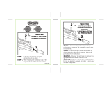
Heavy-Duty Gate Latch
Installation Instructions
• English
........................................................
1
• Français
......................................................
6
• Español
.......................................................
11

2
Gate
Safety Glasses
Pencil
Drill
3/32" Drill Bits
Phillips Driver Bits
7 mm Wrench
Needle Nose Pliers
TOOLS NEEDED:
BEFORE YOU BEGIN:
Vinyl gate posts require an internal support
system for weight-bearing purposes and
therefore wooden inserts or a post stiffener
is required. Post stiffener needs to be
purchased separately.
WARNING:
• Improper installation of this product can result in personal injury. Always wear safety goggles when
cutting, drilling and assembling the product.
• Incorrect installation may cause harm to the gate or individual.
• Not pool code approved.
NOTICE:
• DO NOT attempt to assemble the kit if parts are missing or damaged.
• DO NOT return the product to the store, for assistance or replacement parts call: 1-800-336-2383.
Top View of Routed Post
Top View of Routed Post
Fence
Purchased
Metal Stiffener
Component list:
QTY Description
1
Heavy-Duty Latch
1
Striker
11
1" Phillips Screws
1
Nylon Spacer
Heavy-Duty Latch
Striker
Nylon Spacer
1" Phillips Screws
To obtain and review a copy of the warranty please go to: BoerboelGateSystems.com/warranty.
You can also contact 1-800-336-2383 or write to Boerboel Gate Solutions, 7830 Freeway Circle,
Middleburg Heights, Ohio 44130 to obtain a copy of the warranty.

3
1
2
Install Latch:
NOTE:
As delivered, the heavy-duty self-latching gate
latch is con gured to be mounted to the left of the
gate (as viewed from inside the gate). If you prefer
to mount the latch to the right of the gate, you
will need to re-con gure it per “To Recon gure for
Right-Side Mounting”.
a.) Hold latch against the side of the post and mark
locations of pilot holes, as shown (Fig. 1).
b.) Drill ve
3
⁄
3
⁄
3
32
⁄32⁄
" pilot holes into the post.
c.) Secure latch to side of post with four 1" phillips
screws (Fig. 2).
d.) Place a screw through the nylon spacer and attach
to top forward hole (Fig. 3). This will stop the arm
from pivoting too far.
Install Striker Bar:
a.) Close the gate and insert striker bar into latch,
while holding it rmly against the gate.
b.) Mark pilot holes through the screw holes (Fig. 4).
c.) Remove striker bar and drill
3
⁄
3
⁄
3
32
⁄32⁄
" pilot holes.
d.) Place striker bar on gate and secure with
six 1" phillips screws
NOTE:
A padlock can be placed through the holes at the
top of the latch for added security.
Post
Post
Latch
Latch
Fig. 1
Post Plate
Fig. 2
Fig. 3
Fig. 4
Nylon
Spacer

4
To Reconfi gure for Right-Side Mounting:
a.) Place the latch on a at surface, with the “ nger”
brackets facing the right, as shown (Fig. 5).
b.) Carefully remove spring from the post plate and
swing arm with small needle-nose pliers, using
caution not to bend or break the hooked ends of
the spring (Fig. 6).
c.) Flip the post plate over so the “ nger” brackets
face the left and re-attach the spring, as shown
(Fig. 7).
d.) Continue installation from Step 1.
Fig. 5
Fig. 6
Fig. 7
“Finger”

BARRETTE OUTDOOR LIVING
7830 FREEWAY CIRCLE
MIDDLEBURG HEIGHTS, OHIO 44130
TEL: (800) 336-2383
WWW.BOERBOELGATESYSTEMS.COM
/