Conversion
English 7
Test for proper ignition:
1. Push down and turn the knob to ignition symbol.
2. Verify that the ignitor/spark module clicks.
3. Once the air has been purged from the supply lines, verify that the burner
lights within four (4) seconds. After burner lights, turn knob to the OFF posi-
tion.
4. Test each rangetop burner in this fashion. Call Service if any of the burners do
not light.
Test flame characteristics on the low setting:
1. Push in and turn the knob to the ignition symbol until the burner ignites.
2. Turn knob to the low setting.
3. Verify that the burner maintains a minimum, steady, flame without going out.
The flame should not lift or blow off of the burner. It should carry over, or sur-
round, the entire burner.
4. Verify that the flame is the right color. It should be blue with an inner and outer
cone. See Figure 6: Checking Flame Characteristics for more information.
5. Test each rangetop burner in this fashion. If any flame goes out, does not
carry over properly or is too large, contact service.
Test flame characteristics on the high setting:
1. Push in and turn the knob to the ignitor symbol until the burner ignites.
2. Turn knob to the high setting.
3. Verify that the burner maintains a steady flame. The flame should not lift or
blow off of the burner. It should carry over, or surround, the entire burner.
4. Verify that the flame is the right color. It should be blue with an inner and outer
cone. See Figure 6: Checking Flame Characteristics for more information.
5. Test each rangetop burner in this fashion.
If any flame does not carry over properly, adjust the bypass jet. Return to “Convert
Cooktop Valves for Propane Use” on page 4. If any flame burns yellow, contact
Service.
Dual Fuel appliance installation is complete when correct color, carryover
and size are verified on each cooktop burner.
For gas appliances, continue to “Test Broil Burner” on page 8.
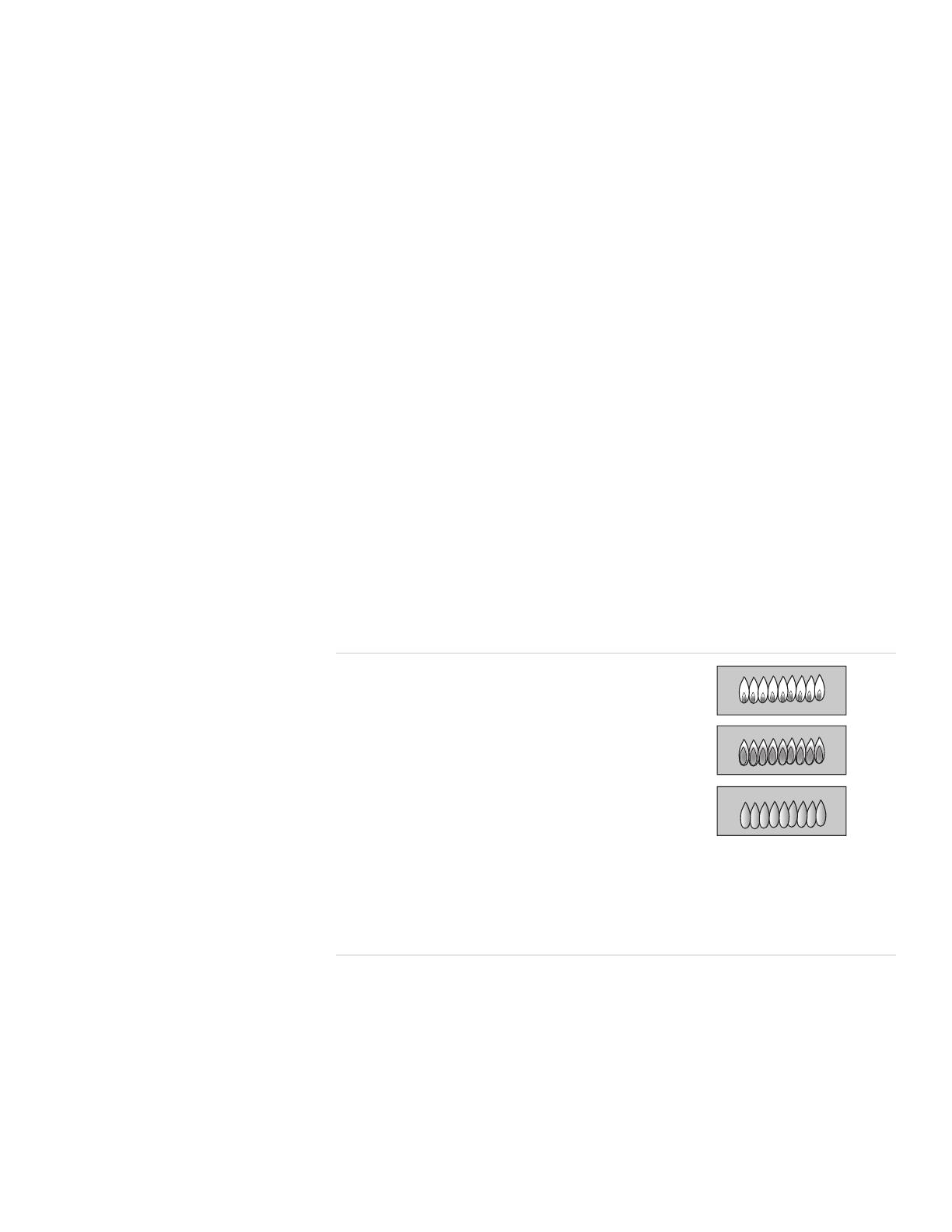
Figure 6: Checking Flame Characteristics
Yellow Flames:
Further adjustment is required.
Yellow Tips on Outer Cones:
Normal for LP Gas.
Soft Blue Flames:
Normal for Natural Gas.
If the flame is completely or mostly yellow, verify that the regulator is set for th
correct fuel. After adjustment, retest.
Some yellow streaking is normal during the initial start-up. Allow unit to operat
4-5 minutes and re-evaluate.


