
Locking Screw
Locking Screw
F. Loosen the locking screw and adjust the oven burner
air shutter. Clockwise rotation will open the air shutter
and increase airflow. Counterclockwise rotation will
close the air shutter and decrease airflow.
NOTES:
• If the flames are yellow, the air shutter on the burner
needs to be opened further.
• If the flames flutter or blow away, the air shutter on
the burner needs to be closed further.
• We highly recommend that the air shutter be fully
opened in case of using LP gas.
G. After flames are adjusted, tighten the locking screw.
H. Program the oven to BROIL and press START. Repeat
Steps E~G.
I. Turn o the oven, install the oven bottom, and replace
the oven racks.
5. Adjusting low flame settings on surface
burners
All surface burner flames should be checked and adjusted
at their lowest setting.
NOTE: Low setting adjustments should always be made
with 2 or more burners operating at the same time.
A. Turn on 2 or more surface burners and set them HI.
B. Quickly turn one of the control knobs counterclockwise
to the lowest setting. The flame should stay lit. If the
flame flutters or goes out, adjust the bypass valve in
the base of the valve stem for that control knob.
C. Pull the control knob for that burner straight o.
D. Insert a small flat-blade screwdriver into the valve stem.
While holding the valve stem in place, turn the bypass
valve adjusting screw counterclockwise to increase the
flame size.
E. Replace the control knob and repeat Steps A and B.
F. Repeat Steps A~E to check and adjust the remaining
surface burners.
Additional low flame check
Quickly open the oven door while a surface burner is set
on LO. If the flame is extinguished, increase the low flame
setting and repeat the test until the flame is stable.
IMPORTANT SAFETY INSTRUCTIONS
WARNING
The following information is intended for use by
persons possessing adequate electrical, electronics,
and mechanical backgrounds and experience. Lack
of proper background and experience during any
repair of a major appliance could result in death,
personal injury, and/or property damage. The
manufacturer or seller cannot be responsible for the
interpretation of this information, nor can it assume
any liability in connection with its use.
• Disconnect the electrical power to the appliance
before servicing.
• Shut o the gas supply to the appliance before
servicing.
• Reconnecting all grounding devices before
reconnecting the electrical power and opening the
gas supply to the appliance.
• All electrical components in this appliance are
grounded. All grounding wires, screws, straps,
nuts, and/or washers must be replaced to their
original position and properly fastened.
•
LP conversion must be performed by a qualified
installer or gas supplier in accordance with the
manufacturer’s instructions and all codes and
requirements of the authority having jurisdiction.
Failure to follow ALL instructions could result
in serious injury or property damage. The
qualified agency performing this work assumes
responsibility for the conversion.
• Know the location of the gas shut-o valve and
how to shut it o if necessary.
• Do not operate the cooktop surface burners or
oven burners of this range when using LP gas
before converting the pressure regulator and
burner orifices for LP gas use. Failure to do so
could cause high flames and toxic fumes which
can result in serious injury.
• Do not mix up or substitute LP gas burner
orifices during the conversion process. Improper
orifice placement will aect burner and cooking
performance and could result in personal injury
and/or product damage.
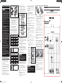
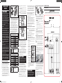
LP GAS (PROPANE) CONVERSION
1. Converting the pressure regulator
The regulator is located in the lower, left-hand rear corner
of the bottom drawer opening.
A. Remove the warming drawer or the storage drawer.
B. Locate the pressure regulator in the rear of the drawer
opening. The pressure regulator can be seen and
accessed through the square hole in the rear wall as
viewed from the front.
C. Using your fingers, turn the red plastic cap and the
dual-purpose orifice spud counterclockwise to remove
them from the pressure regulator.
D. Completely remove the cap from the spud and the
threads and reinstall it on the opposite side of the spud.
A. Remove the surface burner grates.
B. Lift o the surface burner caps and the surface burner
heads from the surface burner manifold cups.
C. Using a 9/32˝ or 7 mm nut driver, remove the burner
orifice from the bottom of each manifold cup.
NOTE: Keep these orifices and note their positions for
future conversion back to natural gas.
Red
White
White
Yellow
NX58H5650WS
Blue
White
White
Yellow
None
NX58H5600SS
Orange
D. Identify the proper orifice by orifice size and color
code for each of the surface burners.
E. Install the proper orifices in each of the burner manifold
cups as shown above. Tighten with a 9/32˝ or 7 mm nut
driver. Do not overtighten.
NOTE: Any other placement of orifices could result in
dangerous operating conditions and/or poor
cooking results.
F. Replace the surface burner heads and caps in the
same location from which they were removed. The
burner heads should be flat on top of the manifold cups
and the caps should be flat on top of the burner heads
to ensure proper, safe operation.
3. Converting the oven burners
The oven has a bake (lower) and a broil (upper) oven
burner. Both burners require the orifices to be changed.
See the charts in column 2 for the proper orifice usage.
To replace the bake (lower) burner orifice:
A. Remove the two screws from the back of the cavity
floor. Lift back to clear the front edge and lift out the
cavity floor.
B. Remove two screws from the front of the bracket bake-
spreader.
C. Lift front the bracket bake spreader and lift out the
bracket-bake spreader.
D. Lift up the burner bake from the holder-bake burner on
the bottom of the drawer.
Valve Stem
Small Screwdriver
NX58H5650WS
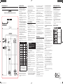
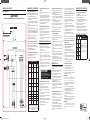
WIRING DIAGRAMS
Model NX58H5650WS
WARNING
POWER MUST BE DISCONNECTED BEFORE SERVICING THIS APPLIANCE.
Plastic Cap
Dual-Purpose
Orifice
Shut-O
Lever
Flip Orifice
to change
application
size.
Pressure
Regulator
E. Reinstall the spud in the pressure regulator so the large,
open LP gas end is exposed. Tighten the spud until it
is finger-tight. Do not overtighten. Replace the plastic
cap over the exposed spud threads.
F. Make sure the gas shut-o lever on the side of the
pressure regulator is in the open position.
G. Replace the warming drawer or the storage drawer.
2. Converting the surface burners
The range comes with low-altitude LP conversion kits.
The kit contains 7 burner orifices. Five of these 7 orifices
are sized and color-coded for surface burner use. The
remaining 2 orifices are for the bake and broil oven burners.
Use the following charts to properly size and replace the
orifices:
BURNER ORIFICE SIZES AND OUTPUT RATINGS
(LP Gas [Propane] 10 in WCP)
Burner location BTU Rate Orifice size [mm]
RF
1
14,500 1.12
RF
2
12,500 1.06
LF
1
11,500 1.04
LF
2
10,000 0.98
RR 4,000 0.62
LR 7,500 0.83
CTR 7,500 0.83
BAKE 15,000 1.15
BROIL 11,500 1.02
¹Model NX58H5650WS ²Model NX58H5600SS
115
Orifice markings:
115 – Denotes 1.15 mm orifice size
opening.
BURNER ORIFICE SIZES AND OUTPUT RATINGS
(Natural Gas 5 in WCP)
Burner location BTU Rate Orifice size [mm]
RF
1
18,000 1.92
RF
2
17,000 1.92
LF 15,000 1.78
RR 5,000 1.01
LR 9,500 1.40
CTR 9,500 1.38
BAKE 18,000 1.90
BROIL 13,500 1.64
¹Model NX58H5650WS ²Model NX58H5600SS
180
Orifice Markings:
180 – Denotes 1.80 mm orifice size
opening.
WARNING
The following adjustments must be made before
turning on the gas to the oven burners. Failure to
do so could result in death and/or serious personal
injury due to high flames and toxic fumes.
E. Using a 9/32˝ or 7mm nut driver and an adjustable
wrench, hold the gas fitting with the wrench and
remove the bake oven burner orifice from the center of
the lower gas fitting.
F. Install a properly sized burner orifice for the lower oven
burner using LP gas.
To replace the broil (upper) burner orifice:
G. Remove 1 screw of bracket HSI-wire
H. Remove 4 screw of bracket-broil spreader to top of
oven.
I. Support the burner-broil with one hand, remove 2 screw
supporting the burner-broil to the front and the rear of
the oven.
J. To replace the nozzle broil-burner, remove the gas
nozzle with a 9/32˝ nut driver.
K. Install a properly sized burner orifice for the upper oven
burner, using LP gas.
L. Position end of upper oven burner over the burner
orifice and secure it in place with the front screw.
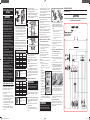
4. Adjusting the air shutter settings on the
oven burners
NOTE: To ensure proper flame characteristics, install and
close the oven door before checking the oven burner
flames.
A. Install and close the oven door.
B. Open the gas shut-o valve to the range.
C. Plug in the power cord or connect the power supply to
the range.
D. Program the oven to BAKE and press START.
E. Visually check the flame characteristics through the
oven window.
• The inner cone of the flames should be
approximately 1/2˝ to 3/4˝ long.
• The visual appearance of the flame will denote the
flame combustion quality.
Soft blue flames are
normal for natural gas
operation.
Yellow tips on outer
cones are normal for
LP gas operation.
Yellow flames are
abnormal for any gas
operation. Further
adjustment required.
Orange flames occur
from foreign particles
in the gas line. The
particles will burn o
and the orange flames
will disappear.
WARNING
Use caution when measuring the flames and
adjusting the air shutter. The burner flames could
burn you or ignite your clothes causing personal
injury and/or death.
Mini-Manual_NX58H56_DG68-00528A_EN+MES+CFR.indb 1 06/02/2014 14:12:59

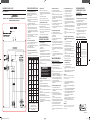
WIRING DIAGRAMS (CONT.)
Model NX58H5600SS
WARNING
POWER MUST BE DISCONNECTED BEFORE SERVICING THIS APPLIANCE.
NX58H5600SS
GAS RANGE CONTROLS
1. Calibrating the oven temperature
The oven temperature can be calibrated to meet your
cooking needs and/or match your previous oven
temperature settings.
A. Remove the warming drawer or the storage drawer.
B. Locate the pressure regulator in the left-rear of the
drawer opening.
C. Using your fingers, turn the red cap and the dual-
purpose orifice counterclockwise to remove them from
the pressure regulator.
D. Remove the cap from the orifice and reinstall it on the
opposite side of the orifice.
E. Reinstall the orifice in the pressure regulator so the
large open LP gas end is exposed. Tighten the orifice
until it is finger-tight. Do not overtighten. Make sure
the red cap is secured over the end of the orifice.
F. Make sure the gas shut-o lever on the side of the
pressure regulator is in the open position.
G. Replace the warming drawer or the storage drawer.
2. Accessing the oven control panel
A. Disconnect or turn o the electrical supply to the range.
B. Shut o the gas shut-o valve to the range.
C. Carefully pull range away from back wall to access the
cover-back guard Wire.
D. Remove the upper rear cover panel.
3. Testing the printed circuit board (PCB)
A. Carefully reconnect the electrical power and perform
the following checks.
B. After checks have been made, disconnect the power to
the range.
RELAY CONTACT OPERATION TEST
RELAY TERMINALS
VOLTAGE IN
COOK MODE
VOLTAGE IN
OFF
Convection
bake
Conv. Bake
to N
120 VAC** 0 VAC
Convection
roast
Conv. Roast
to N
120 VAC** 0 VAC
Warming
drawer*
Warming
Dwr to N
0 VAC (in
Self-Clean)
120 VAC
Favorite
Cook
Cooking
Cycle to N
120 VAC 0 VAC
Self-clean
Self-Clean
to N
120 VAC 0 VAC
Bake Bake to N 120 VAC** 0 VAC
Broil Broil to N 120 VAC** 0 VAC
Keep Warm Warm to N 120 VAC 0 VAC
Bread Proof Proof to N 120 VAC 0 VAC
Oven light Light to L1 120 VAC 0 VAC
*NX58H5650WS only
**Be sure to select a temperature or setting.
**120 VAC to Bake and Cook Time only.
Remaining circuits are deactivated until Sabbath
circuit is deactivated.
4. Replacing the PCB
A. Mark and disconnect the wires going to the PCB.
B. Remove 17 screws and cover wire LT/RT, cover-
back guard wire, cover-back main wire, and cover-
convection.
WARMING DRAWER SERVICING
(Model NX58H5650WS)
1. Warming drawer element replacement
A. Disconnect the electrical power to the range.
B. Shut o the gas supply to the range.
C. Pull out the warming drawer. Press down the left glide
lever, lift up on the right glide lever, and then remove
the drawer from the drawer opening.
D. Disconnect the connector from the back wall of the
warming drawer opening.
E. Remove the bottom screw and the heater-warming
drawer from the back wall of the warming drawer
opening.
F. Reverse the order to install and connect the new heater
warming drawer.
FAILURE CODE CHART
FAILURE
CODE
CAUSE SOLUTION
Shorted Key.
Press the OFF/CLEAR pad and restart
the oven.
If the problem persists, disconnect
all power to the range for at least 30
seconds and then reconnect the power.
If this does not solve the problem, call
for service. See bottom of this chart.
Oven sensor
opened
problem.
Oven sensor
shorted
problem.
Oven
overheating.
Door locking
error.
DG68-00528A-00
C. Remove 2 screws from the Holder-PCB.
D. Replace the PCB and secure with 2 screws.
E. Reconnect all wires from where they were removed.
5. Spark module replacement
The spark module is located behind the upper rear cover
panel on the lower-right side.
A. Mark and disconnect the wires going to the spark
module.
B. Remove 2 screws and the spark module from the
backguard.
C. Install new spark module in the backguard and secure
with 2 screws.
D. Reconnect wires from where they were removed.
COOKTOP SERVICING
1. Removing the cooktop
A. Disconnect electrical power to the range.
B. Shut o the gas shut-o valve in the gas supply line to
the range.
C. Open the door or remove it.
D. Pull burner control knobs straight o to remove them
from the valve shafts.
E. Remove 2 screws from the top, 2 screws from the front
and 4 screws from the bottom of the chassis manifold
panel.
F. Remove the chassis manifold panel from the front of
the range.
G. Place a finger behind each side of the switch ignition
and pull it straight out to release it from the control
shaft. Repeat for each switch.
H. Disconnect the wires at the connectors.
2. Door latch replacement
A. Remove the oven door and the cooktop frame as
described above.
B. Remove the control knob and the chassis manifold.
C. Remove the Assy’ tube-manifold with a wrench.
D. Remove 2 screws from the Bracket-Latch sub to the
rear of the range.
E. Disconnect wires of the door latch to the rear of the
range and remove it.
F. Remove 2 screws holding the Assy bracket-latch rear
to the rear of the range.
G. Remove the latch-rod from the Assy bracket-latch front.
H. Remove 2 screws holding the Assy bracket-latch front
to the front of cavity.
I. After replacement, reverse the order to install the ASSY
DOOR LATCH.
3. Electrode/harness replacement
A. Remove cooktop as described above.
B.
Remove the cover wire LT/RT and cover-back guard wire.
C.
Carefully remove electrode locking clips from the bottom
of the electrodes on the burner cups. Lift and slide the
electrode wire out of the slot on the burner cup.
WARNING
Do not bend the aluminum tubing to the surface
burner cups. Bending can damage the tubing or
fittings resulting in death, personal injury, fire,
and/or product damage.
D. Trace electrode wire back to the starter module and
disconnect the wire from the spark module.
E. Connect new electrode harness to the spark module
in the same location from where the old harness was
removed.
F. Insert electrode in the slot in the burner cup and secure
it in place with the locking clip.
4. Ignition switch harness replacement
A. Disconnect electrical power to the range.
B. Shut o the gas shut-o valve in the gas supply line to
the range.
C. Open the door or remove it.
D. Pull burner control knobs straight o to remove them
from the valve shafts.
E. Remove 2 screws from the top, 2 screws from the front
and 4 screws from the bottom of the chassis manifold
panel.
F. Remove the chassis manifold panel from the front of
the range.
G. Place a finger behind each side of the switch ignition
and pull it straight out to release it from the control
shaft. Repeat for each switch.
H. Disconnect the wires at the connectors.
I. Connect the new ignition switch harness to the wire
connectors from where the old harness was removed
and install the new harness in reverse order.
OVEN SERVICING
1. Oven temperature sensor replacement
A. Disconnect electrical power to the range.
B. Open the oven door and remove the oven racks.
C. Disconnect connector of the sensor thermister to the
rear of the range.
D. Remove 2 screws securing the oven temperature
sensor to the upper left-hand corner of the rear wall.
E. Carefully pull out the sensor wire leads until the wire
connectors appear. NOTE: If the wire connectors
cannot be accessed from inside the oven, remove the
upper rear cover panel, mark the wires, and disconnect
them from behind the oven.
F. Reverse the order to install a new oven temperature
sensor.
2. Lower burner replacement (bake)
A. Turn o the electrical supply going to the range.
B. Shut o the gas shut-o valve in the gas supply line to
the range.
C. Open the oven door and remove the racks from inside
the oven.
D. Pull on the wires or the connector until the wire
connector appears from the back wall of the warming
drawer opening.
E. Disconnect the connector of HSI of the burner bake.
F. Remove the two screws from the back of the cavity
floor. Lift back to clear the front edge and lift out the
cavity floor.
G. Remove 2 screws from the front of the bracket bake-
spreader.
H. Lift front the bracket bake-spreader and lift out the
bracket-bake spreader.
I. Lift up the burner bake from the holder-bake burner on
the bottom of the drawer.
J. Reverse the order to install a new bake burner.
3. Upper burner replacement (broil)
A. Disconnect electrical power to the range.
B. Shut o the gas shut-o valve to the range.
C. Open the oven door and remove the racks
D. Remove cover-back main wire to the rear of the oven.
E. Disconnect the wires or the connector of the HSI.
F. Remove 1 screw of bracket HSI-wire and remove 4
screws of bracket-broil spreader to top of oven.
G. Support the burner-broil with one hand, remove 2
screw supporting the burner-broil to the front and the
rear of the oven.
H. Pull the upper Assy-burner broil spreader to disconnect
it from the holder nozzle-broil on the rear wall of the
oven.
I. Carefully remove Assy-burner broil spreader.
J. Reverse the order to install a new bake burner.
4. Glow bar ignitor replacement (hot surface
ignitor)
A. Disconnect electrical power to the range.
B. Shut o the gas supply to the range.
C. Open the oven door and remove the oven racks.
D. Remove the oven burner closest to the faulty ignitor.
(See burner replacement instructions.)
E. Remove 2 screws securing the glow bar ignitor.
F. Carefully pull the wire leads until the wire connectors
appear.
G. Reconnect new ignitor and reassemble the oven in
reverse order.
5. Assy safety valve (with pressure regulator)
A. Disconnect electrical powe to the range.
B. Shut o the gas supply to the range.
C. Remove the regulator support bracket from the rear of
the range
D. Carefully identify and mark the wires going to the ASSY
VALVE SAFETY. Disconnect the 4 wires.
WARNING
Cross-wiring the wires to the ASSY VALVE SAFETY creates
an explosion hazard that can result in death, personal injury,
and/or property and product damage.
E. Disconnect the 3 gas lines from the ASSY VALVE
SAFETY. Do not bend or crimp gas lines during
removal.
F. Remove gas fittings from the ASSY VALVE SAFETY.
G. Remove 4 screws and the ASSY VALVE SAFETY from
the back wall of the warming drawer opening.
H. Install the new ASSY VALVE SAFETY from the back
wall of the warming drawer with 4 screws.
I. Reconnect gas lines to the ASSY VALVE SAFETY.
J. Reconnect wire connectors in their original positions.
NOTE: Check all gas lines and fittings for leaks before
operation.
WARNING
Cross-wiring the wires to the gas control valve creates an
explosion hazard that can result in death, personal injury, and/
or property and product damage.
This manual is made with 100 % recycled paper.
Mini-Manual_NX58H56_DG68-00528A_EN+MES+CFR.indb 2 06/02/2014 14:13:01
Page is loading ...
Page is loading ...
Page is loading ...
Page is loading ...
-
 1
1
-
 2
2
-
 3
3
-
 4
4
-
 5
5
-
 6
6


Ask a question and I''ll find the answer in the document
Finding information in a document is now easier with AI
in other languages
- français: Samsung NX58H5600SS Manuel utilisateur
- español: Samsung NX58H5600SS Manual de usuario
Related papers
-
Samsung NX58H5600SS User manual
-
-
Samsung NX58F5700WS User guide
-
-
-
-
Samsung NX58R5601SS User guide
-
Samsung NX58M6650WS/AC Installation guide
-
-
Other documents
-
Siemens HG2416UC/01 Supplemental
-
Siemens HG2528UC/01 User manual
-
American Standard 132433 Installation guide
-
Rubi RMP300ST1 Installation guide
-
Bosch HDI8054 Serie Installation guide
-
Bosch HGI8054UC Installation guide
-
GE JGBS62DEKWW LP Conversion
-
-
Frigidaire FFGH2422US Product information
-
Thermador PRD486NLGU User manual