English 8 9001080874 Rev A
Test the Installation
Test for Gas Leaks
Leak testing is to be conducted by the installer according to
the instructions given in this section.
Apply Leak Detection Fluid
Turn on gas. Apply a non-corrosive leak detection fluid to
all joints and fittings in the gas connection between the
shutoff valve and the range. Include gas fittings and joints
in the range if connections may have been disturbed during
installation. Bubbles appearing around fittings and
connections indicate a leak.
If a leak appears, turn off supply line gas shutoff valve and
tighten connections. Retest for leaks by reapplying a non-
corrosive leak detection fluid and then turn on the supply
line gas shutoff valve. When leak check is complete (no
bubbles appear), test is complete. Wipe off all detection
fluid residue.
Do not continue to the next step until all leaks are
eliminated.
Test Electric Ignition
Turn on power at breaker.
Test Cooktop Burners
Each burner must be tested for proper lighting, proper
flame characteristics on the LOW setting and proper flame
characteristics on the HIGH setting.
Test for Proper Ignition
1. Push down and turn the knob to ignition symbol.
2. Verify that the igniter/spark module clicks.
3. Once the air has been purged from the supply lines,
verify that the burner lights within four (4) seconds.
After burner lights, turn knob to the OFF position.
4. Test each rangetop burner in this fashion. Call Service
if any of the burners do not light.
Test Flame Characteristics on the Low Setting
1. Push in and turn the knob to the ignition symbol until
the burner ignites.
2. Let the burner warm up for one (1) minute.
3. Turn knob to the LOW setting.
4. Verify that the burner maintains a minimum, steady
flame without going out. The flame should not lift or
blow off of the burner. It should carry over or surround
the entire burner.
5. Verify that the flame is the right color. See Figure 4
“Checking Flame Characteristics” for more information.
6. Test each rangetop burner in this fashion. If any flame
goes out, does not carry over properly or is too large,
contact Service.
Test Flame Characteristics on the High Setting
1. Push in and turn the knob to the igniter symbol until the
burner ignites.
2. Turn knob to the HIGH setting.
3. Verify that the burner maintains a steady flame. The
flame should not lift or blow off of the burner. It should
carry over, or surround, the entire burner.
4. Verify that the flame is the right color. See Figure 4:
“Checking Flame Characteristics” for more information.
5. Test each rangetop burner in this fashion.
If any flame goes out, does not carry over properly or is too
large, contact Service.
If any flame does not carry over properly, adjust the bypass
screw. Return to “” on page 5. If any flame burns yellow,
contact Service.
Dual Fuel appliance installation is complete when cor-
rect color, carryover and size are verified on each
cooktop burner.
m
WARNING
Never check for leaks with a flame.
ã
CAUTION
If the display flashes and beeps, the polarity of the
wiring may be reversed. Reversed polarity can
damage the range and can be an electrical shock
hazard. Immediately switch off power at the breaker
and return to installation instructions.
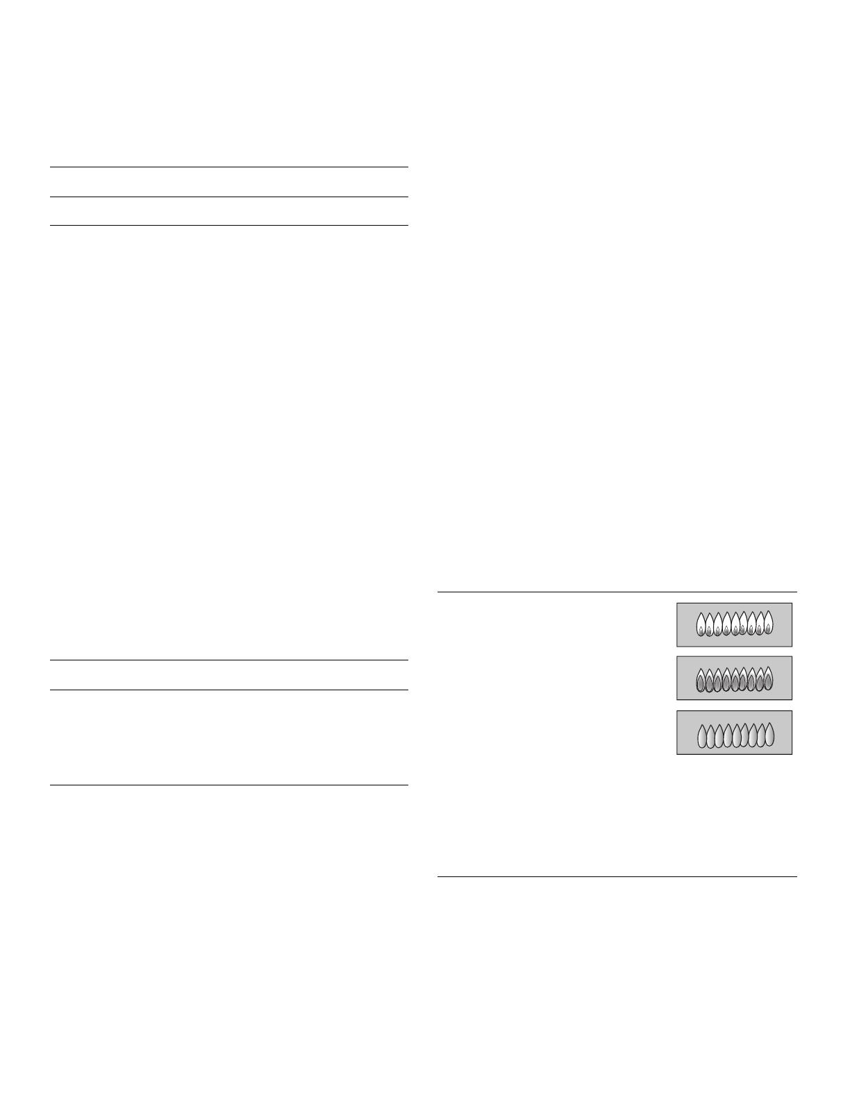
Figure 4: Checking Flame Characteristics
Yellow Flames:
Further adjustment is required.
Yellow Tips on Outer Cones:
Normal for LP Gas.
Soft Blue Flames:
Normal for Natural Gas.
If the flame is completely or mostly
yellow, verify that the regulator is set for the correct fuel.
After adjustment, retest.
Some yellow streaking is normal during the initial
start-up. Allow unit to operate 4-5 minutes and re-
evaluate before making adjustments.


