Page is loading ...

S-550i
Integrated Amplifier
QUICK SETUP GUIDE
Getting Started
THE LEADER IN AUDIO ENGINEERING
Thank you for your purchase of the Krell S-550i Remote Control Integrated
Amplifier. This fully integrated amplifier and preamplifier has a discrete signal
path from input to output and employs a wide bandwidth design with low nega-
tive feedback for sonic accuracy throughout the frequency spectrum. All circuits
up to the driver stage operate in pure Class A.
Krell’s new surface mount technology (SMT) means that the S-550i is an inte-
grated amplifier with big power—275 Watts per channel—that does not require
big space. SMT allows individual circuit elements to be placed very close
together. This shortens signal paths and allows circuit elements to operate at
the same temperature, resulting in more accurate signal transfer and enhanced
reliablilty.
The S-550i is easy to operate and integrate into your system. The remote control
accesses all amplifier functions, and remote control connection options allow the
S-550i to be easily connected with other components. The Theater Throughput
feature provides easy integration of the amplifier into a home theater system.
Do not place the integrated amplifier where it could be exposed to dripping or splashing.
Do not remove or bypass the ground pin on the end of the AC cord. This may cause radio
frequency interference (RFI) to be introduced into your playback system.
The ventilation slots on the top and bottom of the integrated amplifier must be unobstructed
at all times during operation. Do not place flammable material on top of or beneath the com-
ponent.
Turn off all systems’ power before connecting the integrated amplifier to any component.
Make sure all cable terminations are of the highest quality, free from frayed ends, short cir-
cuits, or cold solder joints.
THERE ARE NO USER-SERVICEABLE PARTS INSIDE ANY KRELL PRODUCT.
1. Open the shipping box and remove the top layer of foam. You will see these
items:
2. Carefully remove all items from the shipping box.
3. Place the preamplifier and power supply in a safe location and remove the pro-
tective plastic wrapping.
Place the S-550i on a firm, level surface, away from excessive heat, humidity, or
moisture. The integrated amplifier requires at least one inch (2.54 cm) of clearance
on each side and at least two inches (5 cm) of clearance above to provide ade-
quate ventilation. Installations inside cabinetry may need extra ventilation.
WARNINGS
Krell S-550i 1
Unpacking
Krell Industries, LLC., 45 Connair Road,Orange, CT 06477-3650 USA
TEL 203-799-9954, FAX 203-891-2028, E-MAIL krell@krellonline.com
WEB SITE http://www.krellonline.com
Connecting the
S-550i
to Your System
Because of its powerful amplifier channels and high-capacity power supply, the
S-550i will benefit from a dedicated AC circuit. Avoid connections through exten-
sion cords or multiple AC adapters. High quality 20 amp AC strips are acceptable.
Please contact your authorized Krell dealer, distributor befor using any devices
designed to alter or stabilize the AC power for the S-550i.
Follow these steps to conect the S-550i to your system.
1. Make sure all power sources and components are off before connecting inputs
and outputs.
2. Neatly organize the wiring between the S-550i and all system components.
Separate AC wires from audio cables to prevent hum or other unwanted noises
from being introduced into the system.
3. Connect the left and right loudspeaker cables to the integrated amplifier's left
and right loudspeaker output terminals (14).
4. Connect the left and right outputs of your source components to the appropri-
ate analog inputs (15, 16, 17) on the S-550i.
5. Use the preamp outputs (19) to connect to an additional power amplifier.
6. Plug the AC cord into the IEC connector (22) on the back panel of the S-550i.
Plug the remaining end into the AC wall receptacle. Turn on the Power Breaker
Switch on the rear panel. The red stand-by LED (2) illuminates and the display
shows the software version.
Note
Use only the power cord provided with the S-550i to make the connection to AC power.
Operation with a power cord other than the one supplied by Krell can induce noise, limit cur-
rent, or otherwise impair the ability of the integrated amplifier to perform optimally.
When powering up any system, alway turn amplifiers on last.
When powering down, always turn amplifiers off first.
1. When the amplifier is in stand-by mode, with the red stand-by LED (2) illumi-
nated, turn the amplifier on by pressing the power button on the front panel
or the power key on the remote control (1). There are audible clicks. The blue
power LED (2) illuminates. The S-550i is now in the operational mode.
2. With the amplifier in the mute position, or the volume control fully attenu-
ated, select a source from the front panel or the remote control (4).
3. Start playing the source.
4. Set the volume to a comfortable listening level using the level knob on the
front panel or the level keys on the remote control (7).
5. To turn the amplifier off, press the power button on the front panel or the
power key on the remote control (1). The red stand-by LED (2) illuminates.
It is now safe to turn off the rest of the system.
The balance function allows adjustment of the left and right balance. The options
are: CENTER, L 1-5 dB <, R 1-5 dB >. The remote control has direct (10) keys to make
these adjustments. For front panel adjustment follow the steps listed below.
1. Press the S-550i's menu button (6), then use the level control knob, to select:
BALANCE.
2. Press the level control knob (8). The display shows (9) the default mode: CENTER.
3. Use the level control knob to select the desired balance option from 1 to +5 dB
in 1 dB increments, left or right.
4. Press the level control knob (8) to confirm the selection. The display reads:
BALANCE.
5. Press the MENU button to return to normal operation.
4 Krell S-550i
Operating the S-550i
This product complies with the
EMC directive (89/336/EEC)
and the low-voltage directive
(73/23/EEC).
1 S-550i chassis
1 iPod dock
1 IEC connector (AC power) cord
1 Owner's Reference
1 Remote control
1 T-10 Torx wrench for remote
2 AAA remote batteries
Placement
AC POWER GUIDELINES
MODEL: S-550i Integrated Amplifier SERIAL NUMBER:
Overview
Channel Balance
Adjustment
This CLASS 1 apparatus must
be connected to a MAINS
socket outlet with a protective
earthing connection.
Krell recommends using balanced
interconnect cables. Balanced
interconnect cables not only
can minimize sonic loss but are
also immune to induced noise,
especially with installations using
long cables. Balanced connec-
tions have 6 dB more gain than
single-ended connections. When
level matching is critical, keep this
gain value in mind.
Note
Save all packing materials. If
you need to ship the S-550i in
the future, repack th unit in its
original packaging to prevent
shipping damage.
The owner's reference for this prod-
uct, including a detailed descrip-
tion of features, technologies, and
warranty is available on the web at:
www.krellonline.com

2 Krell S-550i Krell S-550i 3
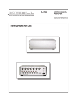
Figure 1 The S-550i Front Panel
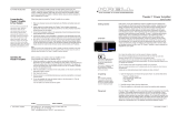
Figure 2 The
Remote Control
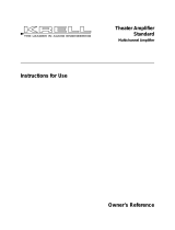
Figure 3 The S-550i Back Panel
This product is manufactured in the United States of America. Krell® is a registered trademark of Krell Industries, LLC., and is restricted for
use by Krell Industries, LLC. its subsidiaries, and authorized agents. Krell Current Mode™ is a trademark of Krell Industries, LLC. All other
trademarks and trade names are registered to their respective companies.
© 2011 by Krell Industries, LLC., All rights reserved
Front Panel
Back Panel
1 Power Button
Use this button to
switch the S-550i
between stand-by and
operational modes.
2 Stand-by LED
The stand-by LED
illuminates red when
the S-550i is plugged
into a standard AC
wall receptacle and
the rear panel power
breaker switch is in the
up position, indicating
that the amplifier is in
the stand-by mode and
ready to be switched to
the operational mode.
The LED illuminates
blue when the S-550i is
in operational mode.
3 Infrared sensor
This receives com-
mands from the remote
control. Make sure this
is not obstructed.
4 S-1, S-2, S-3, B-1 and
iPod Buttons
Use these buttons to
select a balanced ana-
log source component
(B-1) via an XLR con-
nector, or a single-
ended analog source
component (S-1,
S-2, or S-3) via single-
ended RCA connec-
tors, or an iPod via a
special 30-pin iPod
dock.
5 Mute button
Use this to mute the S-
550i output. To unmute,
press the mute button
again.
6 Menu button
Use this to access the
menu functions of the
S-550i.
7 Level Control knob /
Level Keys
The level knob on the
front panel or the level
keys on the remote
control adjust the
amplifier output level.
The output level is
indicated numerically
on the front panel dis-
play, with a range from
0-151.
8 Level Control knob /
Enter Key
Press the level knob
or use the enter key
to configure the menu
functions of the S-550i.
9 Front Panel Display
The front panel dis-
play shows the input
selected, volume and
balance levels, and
Theater Throughput
status.
14 Loudspeaker Outputs
The S-550i is equipped
with standard binding
posts for each amplifier
channel.
15 Balanced Analog Inputs
The S-550i is equipped
with one pair of balanced
(B-1) inputs via XLR con-
nectors.
16 Single-Ended Analog
Inputs
The S-550i is equipped
with three pairs of single-
ended (S-1, S-2, or S-3)
inputs via RCA connec-
tors.
17 iPod Input
The S-550i is equipped
with a balanced stereo
iPod input via a locking
30-pin connector. The
required iPod dock is
supplied.
18 RS-232
The RS-232 port receives
messages from a com-
puter-based control sys-
tem, providing integrated
controls of all integrated
functions. The RS-232
input uses a 9-pin D-sub-
miniature connector.
19 Preamp Outputs
The S-550i is equipped
with a pair of single-
ended preamplifier
oututs.
20 RC-5 In
The S-550i is equipped
with an RC-5 input that
makes custom instal-
lation easy and secure
by accepting baseband
RC-5 input commands
from a remote IR detec-
tor or hardwired remote
controllers.
21 12 VDC In/Out (12 V
trigger)
The 12 V Trigger input
allows you to place the
S-550i into the stand-
by or operational mode
from other components.
The 12 V trigger output
allows the S-550i to
turn other components
on or off.
22 IEC Connector
The connector is for use
with the provided IEC stan-
dard 20 amp power cord.
This connector and power
cord must remain unob-
structed for easy removal
in case of emergency.
23 Speaker Fuses
The speaker fuses pro-
tect the S-550i and the
loudspeakers in case of
overload, short circuit, or
malfunction.
24 AC Power Breaker
Switch
Use this switch to change
the S-550i from off to the
stand-by mode.
Keys labeled 1 to 8
have the same function
(and callout number) as
the front panel controls.
10 BAL (Balance) Keys
Use these keys to shift
the balance to the left
or the right channel.
11 SEL (Select) Key
Used to select
advanced meter or dis-
play functions on other
current Krell products.
12 Direct iPod Functions
With an iPod con-
nected to the special
iPod dock, basic con-
trol functions are avail-
able from the remote
control.
13 CD / DVD Transport
Control
Used to control basic
CD / DVD functions
on other current Krell
products (S-350a).
Note
The remote comes with
two AAA batteries that
have to be installed.
Use the supplied Torx
wrench to remove the
battery panel, then
install the batteries.
Remote
Control
Figure 4 Connection Diagram
/