Page is loading ...

13
Maintenance
Maintenance Schedule
This RO system was designed to ensure ease of use and low maintenance. If the lters are
changed regularly as suggested below and is run within the suggested ouput capacity, the RO
system should work properly for many years.
To assist with maintaining proper care of the RO system, use the System Service Schedule on
page 17 to keep track of completed maintenace on the RO system.
Important!
It is important to change the lters for stages 1, 2 and 3 at least every 6-12 months. The rst 3 lters protect the RO mem-
brane. If the lters are not changed, the membrane will be damaged and the RO system will be contaminated.
Replace every 6-12 Months
If water source is from a private well or water source with high
levels of heavy sediments; lter may need to be changed sooner.
Stage-1
Sediment Filter
Replace every 6-12 Months
If water source is from a private well or water source with high
levels of heavy sediments; lter may need to be changed sooner.
Stage-2 and Stage-3
Carbon Filter
Replace every 2-3 Years
Dependent on proper maintenance of stages 1-3 and level of
water usage.
Stage-4
RO Membrane
Replace every 2,500 Gallons (9,500 Liters)
Usually replaced at the same time as the RO membrane.
Stage-5
Post Carbon Filter
Replacement Filters
Olympia Water Systems oers replacement lters for both the OROS-50 and OROS-80 Re-
verse Osmosis water ltration systems. For purchasing information for replacement lters,
please visit our website at www.olympialtration.com.

14
Filter Replacement
I. Turn o Cold Water & Tank Valve: Turn cold water supply and tank ball valve to OFF
positions. Turn system faucet to the ON position to release any built up pressure in the
RO system. Once pressure has been released, turn system faucet to OFF position.
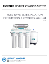
II. Open Housings: See Fig. 19. Starting with the 1st stage, use the large provided wrench
remove the lter housings one at a time by turning counter-clockwise.
III. Replace Filters: Remove and discard the 3 used lters from the housings. Rinse out
each housing to ensure there is no remaining dirt or particles still in the lter housings.
If necessary, wash the housings by hand with a mild soap before rinsing. See Fig. 20.
Insert the new 1st stage sediment lter and the 2nd and 3rd stage carbon block lters
into the corrosponding lter housings.
IV. Close Housings: Starting with the 1st Stage housing on the right, hand twist the hous-
ing onto the main bracket turning clockwise under the 1st Stage label. Using the pro-
vided large wrench, completely tighten the 1st Stage housing onto the main system
bracket. One at a time, hand twist and then tighten with the provided large wrench, the
2nd Stage and 3rd Stage housings under their corrosponding labels on the main sys-
tem bracket. See Fig. 21.
V. Check for Leaks: Turn cold water supply and tank ball valve to ON positions. Check
valves, ttings, tubing connections and housings to ensure there are no leaks.
Fig. 19 Fig. 20 Fig. 21
1
2
3

15
RO Membrane Replacement
I. Turn o Cold Water & Tank Valve: Turn cold water supply and tank ball valve to OFF
positions. Turn system faucet to the ON position to release any built up pressure in the
RO system. Once pressure has been released, turn system faucet to OFF position.
II. Remove Tubing from Housing: See Fig. 22. Remove BLUE tubing lock clip and remove
the tubing from the cap of the RO housing on the main system bracket. Using the pro-
vided small wrench, remove the RO housing cap by turning counter-clockwise.
III. Replace Membrane: Remove and discard the used RO membrane. See Fig. 23. Re-
move and discard the plastic on the new RO membrane and insert the double banded
end of the new RO membrane into the RO housing rst.
IV. Close Housing: Hand twist the RO housing cap back onto the RO housing by turning
clockwise. Using the provided small wrench, completely tighten the cap onto the RO
housing. See Fig. 24. Re-insert tubing into RO housing cap and re-attach BLUE tubing
lock clip to secure tubing.
V. Check for Leaks: Turn cold water supply and tank ball valve to ON positions. Check
valves, ttings, tubing connections and housings to ensure there are no leaks.
VI. Flush Membrane: Allow the RO system to run for approximately 3 hours to ll the tank.
When the tank is lled, the RO system will automatically shut-o. The rst tank of water
must be drained to ush the new RO membrane. Do NOT use the rst tank of water.
Turn the RO system faucet to the ON position to drain the tank. The tank is empty when
there is a noticable drop in water pressure from the RO system faucet. Once the tank is
empty, turn the system faucet OFF.
Fig. 22
Fig. 23
Fig. 24

16
Post Filter Replacement
It is recommended to replace the post carbon lter at the same time the RO membrane is
replaced.
I. Turn o Cold Water & Tank Valve: Turn cold water supply and tank ball valve to OFF
positions. Turn system faucet to the ON position to release any built up pressure in the
RO system. Once pressure has been released, turn system faucet to OFF position.
II. Remove Tubing & Filter: See Fig. 25. Remove BLUE tubing lock clips and tubing from
each of the 3 tubing connections attached to the 5th stage post carbon lter. Remove
the quick connect tee (Point A) from the lter as it will need to be installed on the re-
placement lter. Remove the used lter from the mounting clips and discard the used
lter.
III. Connect Fittings to New Filter: When placing the new 5th stage post carbon lter on
the main system bracket, ensure that the FLOW arrow on the lter is pointing towards
the water output (BLUE tubing). See Fig. 25. Re-insert the quick connect tee (Point A)
and the 3 tubes into the new 5th stage lter and re-attach the 3 BLUE tubing lock clips
to secure tubing connections.
IV. Check for Leaks: Turn cold water supply and tank ball valve to ON positions. Check
valves, ttings, tubing connections and housings to ensure there are no leaks.
V. Flush Filter: Allow the RO system to run for approximately 3 hours to ll the tank.
When the tank is lled, the RO system will automatically shut-o. The rst tank of water
must be drained to ush the new post carbon lter. Do NOT use the rst tank of water.
Turn the RO system faucet to the ON position to drain the tank. The tank is empty when
there is a noticable drop in water pressure from the RO system faucet. Once the tank is
empty, turn the system faucet OFF.
Fig. 25
A

17
System Service Record
Date 1st Stage
Sediment
2nd Stage
Carbon
3rd Stage
Carbon
RO
Membrane
Post-Filter
Carbon
Notes:
Date of Purchase: Date of Install: Installed By:

2 0917-1
Alkaline Filter Replacement Guide
The alkaline lter should be replaced every 6 months. Please follow the 6th stage alkaline lter replace-
ment steps below.
I. Turn o Cold Water & Tank Valve: Turn cold water supply and tank ball valve to OFF positions.
Turn system faucet to the ON position to release any built up pressure in the RO system. Once
pressure has been released, turn system faucet to OFF position.
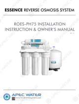
II. Remove Tubing & Filter: See Fig. 1. Remove BLUE tubing lock clips and tubing from both sides
(Points A and B) of the used alkaline lter. Remove and discard the used lter.
III. Installing the New Filter on the System: When placing the new 6th stage alkaline lter on the
main system bracket, ensure that the FLOW arrow on the lter is pointing towards the water out-
put to the faucet (BLUE tubing). Remove the end plugs from both quick connect ttings on the
new alkaline lter.
IV. Connect Tubing to the New Filter: See Fig. 1. Re-insert the tubing into both sides (Points A and B)
of the alkaline lter and re-attach the 2 BLUE tubing lock clips to secure tubing connections.
V. Check for Leaks: Turn cold water supply and tank ball valve to ON positions. Check valves, ttings,
tubing connections and housings to ensure there are no leaks.
VI. Flush Filter: Allow the RO system to run for approximately 3 hours to ll the tank. When the tank
is lled, the RO system will automatically shut-o. The rst tank of water must be drained to ush
the new alkaline lter. Do NOT use the rst tank of water. Turn the RO system faucet to the ON
position to drain the tank. The tank is empty when there is a noticable drop in water pressure from
the RO system faucet. Once the tank is empty, turn the system faucet OFF.
Fig. 1
A B
/