Page is loading ...

INSTALLATION INSTRUCTION
& OWNER’S MANUAL
Olympia Water Systems • www.olympialtration.com Manual Version 1.2, 2016 Nov. All Rights Reserved.
System Tested and Certied by NSF International against NSF/ANSI 42 for the reduction of Chlorine, Taste
and Odor and 58 for the reduction of Total Dissolved Solids. Please refer to the Performance Data Sheet for
complete reduction data.


1
Table of Content
Introduction
About Your Reverse Osmosis System 2
Filter Stages 2
Before Installation
Inspect the System 3
Recommended Tools List 3
Operating Parameter 3
General Installation Requirements 3
How to Use Quick Connect Fittings 3
Included Components 4
System Itemization 4
Installation
Filter Housing Assembly 5
RO Membrane Installation 6
Positioning the System 7
Feed Water Connection 7
Drain Saddle Connection 8
Mounting the Faucet 9
Connecting the Tank 10
Connecting the System 11
System Flow Diagram 11
System Start-Up 12
Maintenance
Maintenance Schedule 13
Filter Replacement 14
RO Membrane Replacement 15
Post Filter Replacement 16
System Service Record 17
Technical Information
Performance Data Sheet 18
Warranty
Limited Product Warranty 19
Please retain this Owner’s Manual for future reference.
It includes information for operation and maintenance of your Olympia Water Systems
Reverse Osmosis water lter system.

2
Introduction
About Your Reverse Osmosis System
Thank you for your purchase of the Olympia Water Systems Reverse Osmosis System.
This 5-Stage Reverse Osmosis System was designed and tested to provide high quality drink-
ing water. The following are brief descriptions of each of the 5 stages in this system.
Caution
Do not use this system with water that is microbiologically unsafe or of unknown quality without adquete pretreatment. This
system is for use on potable water only.
Filter Stages
Cartridge Filters Model Filter Description Service Life
Stage 1
5 Micron Sediment Filter
OROS-PRESF Polypropylene lter for removal of
sand, silt, dirt and rust particles.
6 Months
Stage 2
5 Micron Carbon Filter
OROS-PRECB Coconut shell carbon block for
removing volatile organic carbon
compounds, insecticides/pesticides
and chemicals.*
6 Months
Stage 3
5 Micron Carbon Filter
OROS-PRECB Coconut shell carbon block for
removing volatile organic carbon
compounds, insecticides/pesticides
and chemicals.*
6 Months
Stage 4
RO Membrane
OROS-ROM50
(50 GPD Membrane)
OROS-ROM80
(80 GPD Membrane)
For removing the following contam-
inants in your water: Arsenic, Barium,
Cadmium, Chromium (Hexavelent),
Chromium (Trivalent), Copper, Turbid-
ity, Fluoride, Lead, Radium 226/228,
Selenium* and TDS.
2-3 Years
Stage 5
Post Carbon Filter
OROS-POST Coconut shell post carbon lter for
chlorine, taste and odor reduction.
2,500 Gallons
(9,463 Liters)
*These claims are based on manufacturer testing. These claims are not certied by NSF.
Replacement Filters
Olympia Water Systems oers replacement lters for both the OROS-50 and OROS-80 Re-
verse Osmosis water ltration systems. For purchasing information for replacement lters,
please visit our website at www.olympialtration.com.

3
Before Installation
Inspect the System
Remove the system and all the included components from the box. Inspect the system and
the connection ttings to ensure nothing has been damaged during shipment. If any part of
the system has been cracked or broken, do NOT proceed with installation. Contact Olympia
Water Systems for an exchange or further information.
Recommended Tools List
• Variable speed drill
• Carbide drill bits: 1/4” (for waste line), 1/2” (for faucet hole) and 1/8” (for pilot holes, not
mandatory)
• 5/8”, 9/16” open-end wrench or adjustable wrench (for faucet installation)
• Phillips screwdriver (for saddle valve installation)
• Measuring tape
Operating Parameter
• Operating pressure: 50 PSI - 100 PSI
• Feed water temperature: 40° - 100°F (5° - 38°C)
General Installation Requirements
• System must be connected to COLD water source only.
• System must be installed in an indoor location; avoiding extreme temperatures and direct
sunlight.
• Ensure installation location can support the weight of the system when it is full of water.
How to Use Quick Connect Fittings
To Attach Tubing
Remove BLUE tubing lock clip. Insert tubing until
it hits the backstop. Pull on insterted tubing to
ensure it is secured and re-attach BLUE tubing
lock clip.
To Release Tubing
Remove BLUE tubing lock clip. Use two ngers
to push in collet to release tubing. While collet is
being held, pull tubing straight out.
1
2
3
1
2
3

4
System Itemization
Included Components
Please ensure you have all of these parts before starting installation.
RO System Head 3 Filters and Housings
Storage Tank Faucet Kit
3/8” Feed Water
Angle Valve
Drain Saddle Valve
Tank Ball Valve
4 Colors of 1/4” Tubing
1. Bracket
2. Membrane Housing
3. Post Carbon Filter
4. Sediment Filter Housing (1st Stage)
5. Carbon Filter Housing (2nd Stage)
6. Carbon Filter Housing (3rd Stage)
7. Automatic Shut-O Valve
8. Flow Restrictor
9. T-Fitting
10. Feed Water Inlet
11. Filter Water Outlet
12. Storage Tank
1
2
3
5
4
6
12
10
11
9
8
7
Housing Wrenches
Teon Tape

5
Installation
Fig. 1 Fig. 2 Fig. 3
Filter Housing Assembly
Remove main system bracket, 3 lters and housings from packaging and assemble the lter
housings onto the main system bracket as follows:
I. Install Filters into Housings: See Fig. 1. Stand 3 housings upright. Check each housing
to ensure the black O-ring is properly seated in its groove.
Remove the plastic from the Polypropylene Sediment Filter and place into the 1st
Stage housing.
Remove the plastic from both Carbon Block Filters and place into the middle (2nd
Stage) and left (3rd Stage) housings.
II. Install Housings onto System: See Fig. 2. Starting with the 1st Stage housing on the
right, hand twist the housing onto the main bracket turning clockwise under the 1st
Stage label. Using the provided large wrench, completely tighten the 1st Stage hous-
ing onto the main system bracket. One at a time, hand twist and then tighten with the
provided large wrench, the 2nd Stage and 3rd Stage housings under their corrospond-
ing labels on the main system bracket. See Fig. 3. Once all three housings are installed,
stand system upright.
1
2
3

6
RO Membrane Installation
Remove the provided RO membrane from the plastic packaging and install into the RO hous-
ing on the main system bracket as follows:
I. Open RO Housing: See Fig. 4. Remove BLUE tubing lock clip and remove the tubing
from the cap of the RO housing on the main system bracket. Using the provided small
wrench, remove the RO housing cap by turning counter-clockwise.
II. Install RO Membrane in Housing: See Fig. 5. Insert the double banded end of the RO
membrane into the RO housing rst.
III. Close RO Housing: Hand twist the RO housing cap back onto the RO housing by turn-
ing clockwise. Using the provided small wrench, completely tighten the cap onto the
RO housing. See Fig. 6. Re-insert tubing into RO housing cap and re-attach BLUE tub-
ing lock clip to secure tubing.
Fig. 4
Fig. 5
Fig. 6

7
Feed Water Connection
Space: Ensure there is sucient space for installation (approximately 16” L x 7” W x 20” H for
the system, 12” D x 18” H for the tank).
The RO system is best installed under a kitchen sink. If there is not enough space under the
kitchen sink, the RO system can be installed where there is a COLD water supply with sucient
water pressure and an outlet to drain waste water from the system.
Mounting: It is not neccessary to mount the RO system to the wall or inside of cabinet. The RO
system can stand upright on the housings in the sink cabinet without being mounted. If you
prefer to mount the system to the wall or inside of cabinet, ensure that the system can be easi-
ly removed for future maintenance.
Important!
The system must be connected to the COLD water supply only. If the cold water supply valve cannot turn o the water at
installation location, the main water supply to the house must be shut-o before installation.
Locate the COLD water supply valve and turn it to the OFF position.
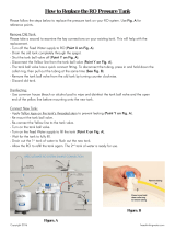
I. Feed Water Angle Valve: See Fig. 7. Attach 3/8” angle valve to COLD water supply line.
Insert one end of the provided WHITE tubing to white quick connection on angle valve.
See Fig. 8. Turning clockwise, tighten tubing connection until RED line on angle valve is
no longer visible. Attach a provided BLUE tubing lock clip to secure tubing connection.
II. Feed Water Connection to System: Locate the WHITE cap insert at the front of the 1st
Stage housing on the main system bracket. Remove BLUE tubing lock clip and WHITE
cap insert from the main system bracket. See Fig. 9. Insert the remaining end of the
WHITE tubing and re-attach the BLUE tubing lock clip to secure tubing connection.
Fig. 7 Fig. 8 Fig. 9
Note
Mounting screws for the RO system are NOT included.
Positioning the System

8
Drain Saddle Connection
Install
Drain Saddle
at Either
Location
Important!
To avoid possible system drainage noise, install drain saddle on the top of horizontal tailpiece or as low as possible on the
vertical tailpiece. Do not install drain saddle close to a garbage disposal outlet as this may cause a blockage in the RO
system drain line.
I. Drain Saddle Location: See Fig. 10. The drain saddle should be installed above the
drain trap on the horizontal or vertical drain tailpiece. If you are installing on the hori-
zontal tailpiece, position the hole on the top side of the tailpiece to prevent waste water
from owing back into the RO system.
II. Prepare the Drain Saddle: Remove nuts and screws from drain saddle to separate
the plastic drain saddle pieces. Remove backing and pre-cut hole from the provided
self-adhesive foam seal. Attach foam seal to drain saddle by lining up the hole on the
foam with the tubing connection hole on the inside of the drain saddle piece.
III. Drill Drain Hole into Pipe: Mark the position of the hole on the drain tailpiece. Drill a
1/4” hole through one side of the drain tailpiece at the marked location.
IV. Align Drain Saddle: See Fig. 11. Position both halves of the drain saddle on the drain
tailpiece so that the tubing connection is lined up with the hole in the drain tailpiece.
Use the screws and nuts to clamp the two halves of the drain saddle onto the drain
tailpiece. Ensure that there is equal spacing between each of the drain saddle halves.
Do not overtighten.
V. Connect Drain Line to the System: Locate the BLACK cap insert attached to the ow
restrictor on the back of the main system bracket. Remove BLUE tubing lock clip and
BLACK cap insert on the ow restrictor. Insert one end of the BLACK tubing and re-at-
tach the BLUE tubing lock clip to secure tubing connection.
VI. Connect Drain Line to Saddle Valve: Measure and mark 1 1/2” from the free end of the
BLACK tubing. Insert remaining end of the BLACK tubing through the opening in the
drain saddle until the marked location on the tubing is ush with the opening. Attach a
provided BLUE tubing lock clip to secure tubing connection.
Fig. 10
Fig. 11

9
Mounting the Faucet
Note
If an existing hole in the sink is available, there is no need to drill a hole for the system faucet. If drilling a hole is necessary,
be sure to clean up all debris from drilling before installing the faucet.
If drilling a hole in the sink or counterop is required to install the faucet, professional installa-
tion by a plumber is highly recommended. Olympia Water Systems is not responsible for any
damage resulting from faucet installation.
I. Faucet Location: If drilling a hole is required to install the the faucet, be sure to choose
a location in the sink or countertop that is convienent for dispening water and has a
sucient at surface for the faucet to be installed properly. Ensure that the threaded
shank of the faucet can be easily accessed from below.
II. For Stainless Steel Sinks: Wear safety glasses to protect your eyes. Ensure location for
hole is clean and dry. A pilot hole or indent with a center punch is recommended be-
fore using the 1/2” drill bit on a stainless steel sink.
For Porcelain Sinks: Wear safety glasses to protect your eyes. Before starting the drill,
apply rm downward pressure on the drill bit until it breaks through the slick surface.
Proceed with caution as porcelain sinks and tile countertops are easily chipped without
applying proper pressure before starting the drill or if the drill bit gets hot.
III. Mount Faucet: See Fig. 12. Using the provided washers, nuts, insert and sleeve; mount
the faucet in the sink or countertop.
IV. Connect Faucet to System: Locate the BLUE cap insert on the left side of the Stage 5
post carbon lter on the main system bracket. Remove BLUE tubing lock clip and BLUE
cap insert from the post carbon lter. Insert the free end of the BLUE tubing and re-at-
tach the BLUE tubing lock clip to secure tubing connection.
Sink or
Countertop
Rubber Gasket
Chrome Base
Black Locating Washer
Lock Washer
Lock Nut
Insert
Sleeve
Compression Nut
Fig. 12

10
Fig. 13
OFF
ON
Connecting the Tank
I. Attach Tank Ball Valve: See Fig. 13. Apply 3-5 wraps of the provided Teon tape to the
threaded output stem on the top of the tank. Screw the provided tank ball valve onto
the tank output stem.
II. Connect Tank Line to Tank: See Fig. 14. Ensure that tank ball valve is in the OFF posi-
tion. Insert one end of the YELLOW tubing into the tank ball valve and attach a provid-
ed BLUE tubing lock clip to secure tubing connection.
III. Connect Tank Line to System: See Fig. 15. Locate the YELLOW cap insert attached to
the right side of the Stage 5 post carbon lter on the main system bracket. Remove
BLUE tubing lock clip and YELLOW cap insert on the post carbon lter. Insert one end
of the YELLOW tubing and re-attach the BLUE tubing lock clip to secure tubing con-
nection.
Fig. 14
Fig. 15

11
Connecting the System
I. Check Tubing Connections: See Fig. 16. Ensure that both ends of all tubing connec-
tions are installed and secured with provided BLUE tubing lock clips.
II. System Water Inlet Connection: See Fig. 17. Check that the feed water angle valve is in
the OFF position.
III. Tank Input & Output: See Fig. 18. Ensure that tank ball valve is in the OFF position.
Fig. 18
Fig. 17
OFF ONONOFF
System Flow Diagram
Tubing Connections
A. Connect WHITE tubing to
Water Supply
B. Connect BLUE tubing to
System Faucet
C. Connect BLACK tubing to
Drain Saddle
D. Connect YELLOW tubing
to Storage Tank
A
C
B
D
Waste Water to Drain
Feed Water from
Cold Water Supply
Fig. 16

12
System Start-Up
I. Turn on Feed Water: Turn cold water supply to ON position. See Fig. 17 on page 11. Turn
feed water angle valve to ON position to allow water to enter the RO system.
II. Open Tank Valve: See Fig. 18 on page 11. Turn tank ball valve to ON position.
III. Check for Leaks: Check valves, ttings, tubing connections and housings to ensure
there are no leaks.
IV. Wait for Tank to Fill: Allow the RO system to run for approximately 3 hours to ll the
tank. When the tank is lled, the RO system will automatically shut-o. The tank is full
when you can no longer hear water running through the lters, or water owing into the
drain pipe.
V. Clean-Up: While RO system is lling the tank for the rst time, clean-up all of the used
tools and work area. Be sure to keep all provided tools in a safe place so they can be
used for future RO system maintenance.
VI. Flushing the Tank: To ush the tank, turn the RO system faucet to the ON position
and drain the water from the tank. The tank is empty when the pressure from the fau-
cet drops from a steady stream to a slow trickle. Upon startup of the system, you may
initially notice the water stream has a black tint. This is caused by the manufacturing of
the carbon lters. You may also notice the smell of chlorine in the water from the saniti-
zation of the rubber bladder in the water tank.
To ush out the carbon and chlorine, you may need to ll and empty the storage tank
up to 5 times, where the water will be clear and you cannot taste the chlorine.
Congratulations, you have successfully completed the installation of your
Olympia Water Systems Reverse Osmosis water lter system!
/