Page is loading ...

Kichler
®
Lighting
7711 East Pleasant Valley Road
P.O. Box 318010
Cleveland, Ohio 44131-8010
Customer Service
866.558.5706
8:30 AM to 5:00 PM EST,
Monday - Friday
Instruction Manual
65" Maor
A Kichler
®
Decor
™
ceiling fan
310136
3066708

1. To reduce the risk of electric shock, insure
electricity has been turned off at the circuit
breaker or fuse box before beginning.
2. All wiring must be in accordance with the
National Electrical Code and local
electrical codes. Electrical installation
should be performed by a qualified
licensed electrician.
3. WARNING: To reduce the risk of fire or
electric shock, do not use this fan with any
solid-state speed control. Use only the
control provided with the fan.
4. WARNING: To reduce the risk of personal
injury, use only the two steel screws (and
lock washers) provided with the outlet box
for mounting to the outlet box. Most outlet
boxes commonly used for the support of
lighting fixtures are not acceptable for fan
support and may need to be replaced,
consult a qualified electrician if in doubt.
5. WARNING: To reduce the risk of fire,
electric shock, or Personal Injury, mount
directly to a structural framing member or
to an outlet box marked 'Acceptable for
Fan Support of 22.7 kg (50 lbs) or less'. For
outlet box mounting, use mounting screws
provided with the outlet box.
6. The fan must be mounted with a minimum
of 7 feet clearance from the trailing edge of
the blades to the floor.
7. To slide the reverse button to operate the
reverse function on this fan. A few seconds
later the fan will slow to a stop and then
reverse direction. NOTE: Fan will not operate
when the reverse switch in the middle.
8. Avoid placing objects in the path of the
blades.
9. To avoid personal injury or damage to the
fan and other items, be cautious when
working around or cleaning the fan.
10. Do not use water or detergents when
cleaning the fan or fan blades. A dry dust
cloth or lightly dampened cloth will be
suitable for most cleaning.
box.
11. After making the electrical connections,
spliced conductors should be turned
upward and pushed carefully up into
outlet box. The wires should be spread
apart with the ground wire and white
(common) wire to one side with the black
(load) wire to the other side of the outlet
12. Electrical diagrams are reference only.
Light kits that are not packed with the fan
must be ETL Listed and marked suitable
for use with the model fan you are
installing. Switches must be ETL General
Use Switches. Refer to the Instructions
packaged with the light kits and switches
for proper assembly.
WARNING
TO REDUCE THE RISK OF PERSONAL
INJURY, DO NOT BEND THE BLADE
BRACKETS (ALSO REFERRED TO AS
FLANGES) DURING ASSEMBLY OR AFTER
INSTALLATION. DO NOT INSERT OBJECTS
IN THE PATH OF THE BLADES.
1
1. SAFETY RULES
WARNING
To reduce the risk of fire, electric shock, or
Personal Injury, mount directly to a structural
framing member or to an outlet box marked
'Acceptable for Fan Support of 22.7 kg(50 lbs)
or less'. For outlet box mounting, use mounting
screws provided with the outlet box.

2
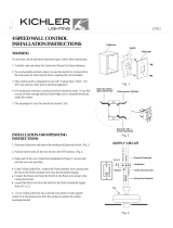
3. PACKAGE CONTENTS
Unpack your fan and check the contents .
You should have the following items:
Philips screw driver
Blade screw driver
11 mm wrench
Step ladder
Wire cutters
2. TOOLS AND MATERIALS REQUIRED
65"Maor
A. Mounting Bracket
B. Ball / Downrod Assembly (1)
C. Canopy
D. Canopy Hole Cover
E. Coupling Cover
F. Motor Body
G. Blade Arm
H. Blade Holder
I. Blade
J. Switch Housing
K. Light Kit
L. LED Module
M. Glass Shade
N. Light Case
O. Package Hardware:
1) Mounting Hardware:
wood screws (2), flat washers (2),
screws (2), lock washers (2),
wire nuts (3)
2) Blade Attachment Hardware:
screws (14)
3) Blade Arm Hardware:
screws (2)
4) Safety Cable Hardware:
wood screw (1), spring washer (1),
flat washer (1)
5) Balance Kit
6) Screw Hardware
screws (3), flat head screws (3)
7) Extra Screw Hardware
screws (3)
A
B
C
D
E
F
J
I
H
K
L
G
M
N
O

4. MOUNTING OPTIONS
Outlet box
Provide strong
support
Recessed
outlet box
Ceiling
mounting
plate
Outlet box
Fig. 1
Fig. 3
Fig. 4
Outlet box
Fig. 2
ANGLED CEILING
MAXIMUM 30
°
ANGLE
3
If there isn't an existing ETL listed mounting
box, then read the following instructions.
Disconnect the power by removing fuses or
turning off circuit breakers.
Secure the outlet box directly to the building
structure. Use appropriate fasteners and
building materials. The outlet box and its
support must be able to fully support the
moving weight of the fan (at least 50 lbs). Do
not use plastic outlet boxes.
Figures 1, 2 and 3 are examples of different
ways to mount the outlet box.
NOTE: If you are installing the ceiling fan on a
sloped (vaulted) ceiling, you may need a
longer downrod to maintain proper clearance
between the tip of the blade and the ceiling.
A minimum clearance of 12" is suggested for
optimal operation.
NOTE: Depending on the location you have
selected for installation, you may need to
purchase and install a "Joist Hanger" for the
support of the outlet box. Make sure the joist
hanger you purchase has been designed for
use with ceiling fans. (Fig. 4)

4
5. HANGING THE FAN
REMEMBER to turn off the power before you
begin installation. This is necessary for your
safety and also the proper programming of the
control system.
To properly install your ceiling fan, follow the
steps below.
Step 1. Before attaching fan to outlet box
(not included), ensure the outlet box is securely
fastened to at least two points to a structural
ceiling member (a loose box will cause the fan
to wobble). Pass the 120 volt supply wires from
the ceiling outlet box through the center of the
ceiling mounting bracket. Install mounting
bracket to outlet box in ceiling using the screws
and washers included with the outlet box or
screws and washers in the hardware bag.
(Fig. 5)
Step 4. Slip the coupling cover, canopy hole cover
and canopy onto the downrod. Carefully reinstall
the hanger ball onto the downrod . Make sure the
cross pin is in the correct position and the set
screws are tight and the wires are not twisted .
( Fig. 8)
Step 2. Remove the hanger ball from downrod
assembly by loosening set screws , removing
the cross pin, and twisting ball out of the rod.
( Fig. 6)
Step 3. Loosen the two set screws and remove
the clip and cross pin from the top coupling of
the motor body.
Carefully feed the fan wires up through the
downrod. Thread the downrod onto the motor
coupling until the cross pin holes are aligned.
Next, replace the cross pin and clip, and tighten
both set screws. (Fig. 7)
Flat Washer
Screw
Fig. 5
Ceiling Mounting Bracket
ETL Listed Outlet Box
Screw
Downrod
Cross Pin
Fig. 6
Set Screw
Hanger Ball
Fig. 7
Fig. 8
65"Maor
Set Screw
Cross Pin
Motor Body
Cross Pin
Clip
Set Screw
Clip
Hanger Ball
Canopy Hole Cover
Coupling Cover
Motor Body
Canopy

5
Step 5. Now lift the motor body into position
and place the hanger ball into the hanger bracket.
Rotate until the "Check Tab" has dropped into
the "Registration Slot " and seats firmly. ( Fig. 9)
The entire motor body should not rotate is this is
done correctly.
6 . INSTALLATION OF SAFETY SUPPORT
(required for Canadian installation ONLY)
WARNING: Failure to properly seat the "Check
Tab" can damage the ceiling fan during operation.
A safety support cable is provided to help prevent
the ceiling fan from failing, please install it as
follows.
Step 1. Drive a wood screw and washers into the
side of the brace that holds the outlet box. Leave
3mm (1/8") of space between the support brace
and the washer. (Fig. 10)
NOTE: Although the safety support cable is
required for Canadian installations only. It’s a good
idea to make the attachment with any installation.
Step 2. Insert the safety cable through the
mounting bracket and one of the holes in the
outlet box into the ceiling. Adjust the length of the
safety cable to reach the screw and washers by
pulling the extra cable through the cable clamp
until the overall length is correct, put the end of the
cable back through the cabel clamp, forming a
loop at the end of the cable. Tighten the cable
clamp securely. Now, put the loop in the end of the
safety cabel over the wood screw and under the
washer. Tighten the wood screw securely. (Fig. 11)
Fig. 9
Safety Cable
Bolt
Wood Screw
Fig. 11
Fig. 10
Flat Washer
Wood Screw
Spring Washer
Outlet Box
Support Brace
Ceiling
Check Tab
Registration Slot

6
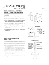
7. MAKE THE ELECTRIC CONNECTIONS
WARNING: To avoid possible electrical shock,
be sure you have turned off the power at the
main circuit panel before wiring.
WARNING: If your house wires are different
colors than referenced in this manual, stop
immediately. A professional electrician is
recommended to determine proper wiring.
Step1. Connect the fan supply BLACK wire
and fan light supply BLUE wire to the BLACK
household supply wire as shown in Fig. 12.
Follow the steps below to connect the fan to
your household wiring. Use the wire
connecting nuts supplied with your fan. Secure
the connector with electrical tape. Make sure
there are no loose wire stands or connections.
Fig. 12
Fig. 13
Fig. 14
BLACK
WHITE
GREEN
Ground to
Mounting
Bracket
Green
Ground
Lead
Outlet Box
Ground
Conductor
WHITE
BLUE
BLACK
SUPPLY CIRCUIT
Mounting Bracket
Shoulder Screw
Canopy
Shoulder Screw
Step 1. Remove one of the two shoulder screws
in the mounting bracket. Loosen the second
shoulder screw without fully removing it.
(Fig. 13)
Step 2. Assemble canopy by rotating key slot in
canopy over shoulder screw in mounting bracket.
Tighten shoulder screw. Fully assemble and
tighten second shoulder screw that was
previously removed. (Fig. 14)
8 . FINISHING THE INSTALLATION
Step 4. After making all of the above
connecting, spread them apart so the GREEN
and WHITE wires to one side of the outlet box
and the BLACK wire toward the other side.
Step 3. Connect GROUND (GREEN) wires
from mounting bracket and downrod ball, to
GROUND (GREEN) or BARE (COPPER) from
house. (Fig. 12)
Step 2. Connect the fan neutral WHITE wire to
the household neutral WHITE wire as shown in
Fig. 12.
65"Maor

7
9. ATTACHING THE FAN BLADES
Step 3. Securely attach and tighten the canopy
hole cover over the shoulder screws in the
mounting bracket utilizing the keyslot twist-lock
feature. (Fig. 15)
NOTE: Before continuing , make sure the power
is disconnected by turning off the circuit breaker
of removing the fuse at the circuit box.
Step 1. Position the blade over the blade holder
with three threaded posts showing. Make sure
the bottom edge of the blade is fully seated
against the blade holder. Attach the blade arm to
the blade and blade holder using the three blade
screws. Do not tighten blade screws until all three
have been inserted. Then, tighten each blade
screws securely. Repeat the procedure for all
remaining blades. (Fig.16)
Step 2. Fasten blade assembly to the holes
located on the bottom of the flywheel. Tighten the
two "pre- installed" motor screws in the blade
arm. Repeat steps for the remaining blades
assemblies. (Fig. 17)
Fig. 15
Fig. 16
Fig. 17
Canopy Hole Cover
Shoulder Screw
Blade
Blade Screw
Blade Arm
Blade Holder
Motor Body
Blade Arm
Flywheel

8
10. INSTALLING THE SWITCH HOUSING
Step 1. Remove the screw nearest the red dot label
on the mounting ring and loosen the other two (do
not remove). Let the 9-pin connector from motor
body through the middle hole of switch housing.
Align the two slot holes on the switch housing over
the 2 screws previously loosened from the mounting
ring. Turn the switch housing until it locks in place at
the narrow end of the key holes. Securely tighten all
three screws. (Fig. 18)
11. INSTALLING THE LIGHT KIT
NOTE: Before continuing installation, confirm that
the power is still turned off at the main circuit
breaker or by removing the correct fuse. Turning
the power off using a wall switch is not sufficient to
prevent electrical stock.
Step 4. Hold the LED module close to the light kit.
Connect the WHITE wires from the light kit and LED
module by pushing the connectors together. Follow
the same procedure with the BLACK wires. Align the
holes on the LED module and light kit and securely
tighten with three screws in hardware bag. (Fig. 20)
Mounting Ring
Switch Housing
Screw
Switch Housing
Light Kit
Screw
Light Kit
Screw
LED Module
Fig. 18
Fig. 19
Fig. 20
Step1. Remove 1 of the 3 screws on switch housing
and loosen the other 2 screws (do not remove).
(Fig. 19)
Step 2. The Square plastic wiring connector from the
motor body and light kit will only fit together one way.
Match up the color on the side of each connector,
then push them together until the snap engages.
(Fig. 19)
Step 3. Align the key holes on the light kit with the 2
screws on the edge of the switch housing. Turn light
kit until it locks in place at the narrow end of the key
holes. Tighten the 2 screws and reinstall the third
screw, making sure all three screws are tight and
secure. (Fig. 19)
65"Maor

12. INSTALLING THE GLASS SHADE AND
LIGHT CASE
13. INSTALLING THE FOB
9
Step 1. Assemble the glass shade to the light kit
by twisting in a clockwise direction. Do not
overtighten. (Fig. 21)
Fig. 21
Fig. 22
Fig. 23
Step 2. Let the reverse switch and 2 pull chains
through the holes on the light case. Attach the
light case to the light kit by using the three flat
head screws in hardware package. (Fig. 22)
Step 1. Attach the decorative pull chain fobs to
the chains comming out of the light case.
Refer to Fig. 23.
Check the ON/OFF operation of the light by
gently pulling on the light switch pull chain.
Check the operation of the fan by gently pulling
on the speed control switch pull chain.
The operation sequence is as follows:
1st pull – High
2nd pull – Medium
3rd pull – Low
4th pull – OFF
Your fan is shipped from the factory with the
reversing switch positioned to circulate air
downward. If airflow is desired in opposite
direction, turn the fan off and wait for the blades
to stop turning, then slide the reversing switch to
the opposite position, and turn the fan on again.
The fan blades will turn in the opposition
direction and reverse the airflow.
Light Kit
Screw
Reverse
Switch
Light Case
Light Kit
Glass Shade
Fob
Reverse
Switch

10
Problem
Fan will not start.
Fan sounds noisy.
Fan wobble.
Remote control
malfunction.
Solution
1. Check circuit fuses or breakers.
2. Check all electrical connections to insure proper contact. CAUTION: Make
sure the main power is OFF when checking any electrical connection.
3. Make sure the transmitter batteries are installed properly. Positive (+) side
facing out.
4. Insure the batteries have a good charge.
1. Make sure all motor housing screws are snug.
2. Make sure the screws that attach the fan blade brackets to the motor are
tight.
3. Make sure wire nut connections are not rubbing against each other or the
interior wall of the switch housing. CAUTION: Make sure main power is off.
4. Allow a 24-hour "breaking-in" period. Most noise associated with a new fan
disappear during this time.
5. If using an optional light kit, make sure the screws securing the glassware are
tight. Make sure the light bulbs are not touching any other component.
6. Do not connect this fan to a wall mounted variable speed control(s). They are
not compatible with ceiling fan motors or remote controls.
7. Make sure the upper canopy is a short distance from the ceiling. It should not
touch the ceiling.
1. Check that all blade and blade arm screws are secure.
2. Most fan wobbling problems are caused when blade levels are unequal.
Check this level by selecting a point on the ceiling above the tip of one of the
blades. Measure this distance. Rotate the fan until the next blade is positioned
for measurement. Repeat for each blade. The distance deviation should be
equal within 1/8".
3. Use the enclosed Blade Balancing Kit if the blade wobble is still noticeable.
4. If the blade wobble is still noticeable, interchanging two adjacent (side by
side) blades can redistribute the weight and possibly result in smoother
operation.
1. Ceiling Fans with remote control systems CAN NOT be operated in
conjunction with any other control system EXCEPT a basic On/Off wall switch,
if desired.
14. TROUBLESHOOTING
15. SPECIFICATIONS
These are approximate measures . They do not include data for any lamps or fixtures attached
to the ceiling fan.
17.5
kgs
N.W.
19.7
kgs
G.W.
3.2'
C.F.RPM
136
95
55
CFM
8803.84
6031.1
3491.64
CFM/W
102.92
135.81
199.98
Fan Size
65"
120High
120
120Low
Volts
0.72
0.52
0.32
Amps
85.54
44.41
17.46
WattsSpeed
Medium
65"Maor
/