Page is loading ...

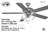
50” Kyte


50” Kyte
WALL CONTROL


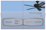
A. Ceiling Bracket Assembly
B. Canopy Assembly
C. Motor Assembly
D. Blade Assembly (2)
E. Shorter Blade Arm (2)
F. Longer Blade Arm (2)
G. Wall Mount Control System
H. Package Hardware:
1) Mounting Hardware: wood screws (2),
flat washers (2), screws (2),
lockwashers (2), wire connectors (3)
2) Safety Cable Hardware: wood screw
(1), spring washer (1), flat washer (1)
3) Blade Arm Hardware: screws (10)
A
C
E
D
B
F
G
H
50” Kyte


Step 2. Remove the screw near by the round dot label and remain it for
later use. Loosen the other two screws without fully removing them. (Fig. 6)
Screw
Fig. 6
Outlet Box
Ceiling Bracket Assembly
Screw
Flat Washer
Fig. 5
50” Kyte

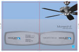
Step 3. Firstly choose the blade arm (part E or part F)
what your want. Slide the blade arms through slots in
motor assembly and attach to the hub using the screws
provided. Make sure the screws securing the blade arms
to the hub are tight and are properly seated. (Fig. 7)
Step 4. Remove the four screws in the motor assembly.
Assemble the canopy assembly to the motor assembly
and securely tighten them with all four screws. Connect
the 9 pin connectors from the canopy assembly to motor
assembly. (Fig. 8)
Motor Assembly
Blade Arm
Screw
Fig. 7
Motor Assembly
Screw
Canopy Assembly
Fig. 8

Step 5. Hang the canopy assembly to the hook on the ceiling
bracket assembly as shown. You can now proceed with electrical
wiring of your fan. (Fig. 9)
Flat Washer
Wood Screw
Spring Washer
Outlet Box
Support Brace
Ceiling
Canopy Assembly
Ceiling Bracket Assembly
Hook
Fig. 9
50” Kyte

Step 1. Set the slide switch in the OFF (-) position. (Fig. 12)
Safety Cable
Bolt
Wood Screw

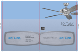
Step 3. Connect the green grounding lead from the ceiling bracket
to the supply grounding, from fan and from wall control conductor (this
may be a bare wire or wire with green colored insulation). Securely
connect wires with a wire connector. Securely connect the white wire
(coming from fan) to the white supply (neutral) wire using a wire
connector. Securely connect the black wire (coming from fan) to the
black wire(TO FAN) from wall control using a wire connector.Connect
the black wire(TO POWER SUPPLY)from wall control to the black
household supply wire using a wire connector.(Fig. 12)
BLACK
(To FAN)
BLACK
GROUND
WHITE
BLACK
(TO POWER SUPPLY)
BLACK
WHITE (NEUTRAL)
Fig. 12
AC 120V INPUT
50” Kyte

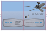
Step 1. Hold the motor assembly and release it from the hook on the ceiling
mounting bracket. Position the round holes near the round dot label on the
motor assembly and ceiling mounting bracket directly. Lift up the motor
assembly, allowing the two ceiling bracket screws to slide into the mating slots.
Rotate the motor assembly until both screws drop into the slot recesses.
Tighten the ceiling bracket screws securely and then install the previously
removed screw into the remaining mating hole. (Fig. 13)
Step 2. Slide the two blade assemblies together as shown and make sure they
are properly seated. Tighten two screws securely. (Fig. 14)
Screw
Motor Assembly
Ceiling Mounting Bracket
Fig. 13
Screw
Blade Assembly
Fig. 14

Step 3. Attach the blade assembly to the blade arms and tighten
screws provided. (Fig. 15) NOTE: Hold up the middle area of the
blade assembly by your hand (see the figure); Do not loosen your
hand prior to completing the installation.
Fig. 15
Motor Assembly
Blade Assembly
Screw
50” Kyte

Fig. 16
Wall Outlet Box
Wall Control
Wall Plate
Fig. 17
WALL CONTROL
control. You can replace an existing
wall switch,or install the wall control to a new outled box.
control

1. The slider is used to set each fan speed separately.
Move it up or down to select the desired speed. (Fig. 18)
1 = High Speed
2 = Medium High Speed
3 = Medium Speed
4 = Low Speed
- = Fan O
NOTE: Turn o and wait for fan to stop before changing the setting of the
forward/reverse slide switch.
18
Fan O
Speed
Fig. 18
Reverse Switch
Fig. 19
50” Kyte


following
modifications
installation. radiate radio
television reception,
50” Kyte
limits
digital
equipment does

/