
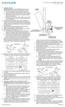
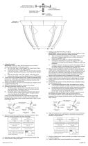
CHAIN DROP INSTALLATION INSTRUCTIONS
1) Pass threaded pipe on end of small loop up through hole in
canopy.
2) Thread lockwasher onto end of threaded pipe protruding
from inside canopy.
3) Thread hexnut onto end of threaded pipe protruding from
inside canopy. Tighten hexnut to secure small loop to canopy.
4) Pass fixture wire from top of fixture through hole in bottom
of large loop. Thread large loop onto threaded pipe on top of
fixture.
5) Attach one end of chain to large loop on top of fixture.
Attach other end of chain to small loop on canopy.
6) Weave fixture wires through chain links no more than 3
inches apart.
7) Pass fixture wires through hole in small loop on canopy and
up through hole in canopy.
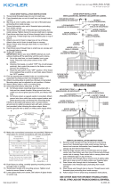
8) TURN OFF POWER.
IMPORTANT: Before you start, NEVER attempt any work
without shutting off the electricity until the work is done.
a) Go to the main fuse, or circuit breaker, box in your
home. Place the main power switch in the “OFF”
position.
b) Unscrew the fuse(s), or switch “OFF” the circuit breaker
switch(s), that control the power to the fixture or room
that you are working on.
c) Place the wall switch in the “OFF” position. If the fixture
to be replaced has a switch or pull chain, place those in
the “OFF” position.
9) Find the appropriate threaded holes on mounting strap.
Assemble mounting screws into threaded holes.
10) Attach mounting strap to outlet box. (Screws not provided).
Mounting strap can be adjusted to suit position of fixture.
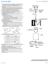
11) Grounding instructions: (See Illus. A or B).
A) On fixtures where mounting strap is provided with a
hole and two raised dimples. Wrap ground wire from
outlet box around green ground screw, and thread into
hole.
B) On fixtures where a cupped washer is provided. Attach
ground wire from outlet box under cupped washer and
green ground screw, and thread into mounting strap.
If fixture is provided with ground wire. Connect fixture
ground wire to outlet box ground wire with wire connector
(not provided.) after following the above steps. Never
connect ground wire to black or white power supply wires.
12) Make wire connections (connectors not provided). Reference
chart below for correct connections and wire accordingly.
13) Push fixture to ceiling, carefully passing mounting screws
through holes in canopy.
14) Thread knurl knobs onto mounting screws. Tighten knurl
knobs to secure fixture to ceiling.
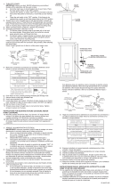
15) Thread end of threaded pipe with bead into hole in bottom
of socket cluster.
16) Pass hole in flat washer over end of threaded pipe. Pass
hole in rubber washer over end of threaded pipe.
17) Raise glass up to fixture. Pass hole in glass over end of
threaded pipe.
18) Pass hole in rubber washer over end of threaded pipe
protruding from bottom of glass. Pass hole in flat washer
over end of threaded pipe. (DO NOT over tighten.)
MOUNTING STRAP
ABRAZADERA DE MONTAJE
LARGE CANOPY
ESCUDETE GRANDE
Date Issued: 8/29/14 IS-43641-US
GREEN GROUND
SCREW
CUPPED
WASHER
A
B
OUTLET BOX
GROUND
FIXTURE
GROUND
DIMPLES
WIRE CONNECTOR
(NOT PROVIDED)
OUTLET BOX
GROUND
GREEN GROUND
SCREW
FIXTURE
GROUND
SEE OTHER SIDE FOR SPANISH TRANSLATIONS.
VEA EL OTRO LADO DE TRADUCCIONES AL ESPAÑOL.
KNURL KNOB
PERILLA ESTRADA
SMALL LOOP
ANILLO PEQUEÑA
CHAIN
CADENA
We’re here to help 866-558-5706
Hrs: M-F 9am to 5pm EST
LOCKWASHER
ARANDELA DE SEGURIDAD
Connect Black or
Red Supply Wire to:
Connect
White Supply Wire to:
Black White
*Parallel cord (round & smooth) *Parallel cord (square & ridged)
Clear, Brown, Gold or Black
without tracer
Clear, Brown, Gold or Black
with tracer
Insulated wire (other than green)
with copper conductor
Insulated wire (other than green)
with silver conductor
*Note: When parallel wires (SPT I & SPT II)
are used. The neutral wire is square shaped
or ridged and the other wire will be round in
shape or smooth (see illus.)
Neutral Wire
HEXNUT
TUERCA HEXAGONAL
19) Thread hexnut onto end of threaded pipe.
20) Pass hole in bottom trim over end of threaded pipe.
21) Thread finial onto end of threaded pipe. (DO NOT over
tighten.)
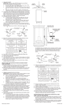
SEMI FLUSH INSTALLATION INSTRUCTIONS
1) Remove small canopy from top of fixture by unscrewing
hexnut from threaded pipe inside small canopy. Remove
hexnut and unscrew lockwasher from threaded pipe. Raise
canopy up and remove from fixture.
2) Take the large canopy with two small holes and one large
center hole. Pass fixture wire from top of fixture body through
center hole in canopy. Pass center hole in canopy down over
end of threaded pipe on top of fixture.
3) Pass fixture wire through hole in lockwasher. Thread
lockwasher onto threaded pipe protruding from inside
canopy.
4) Pass fixture wire through hole in hexnut. Thread hexnut onto
threaded pipe protruding from inside canopy.
5) Follow steps 8-21 in Chain Drop Installation Instructions.
SOCKET CLUSTER
GRUPO DEL PORTALÁMPARAS
THREADED PIPE
TUBO ROSCADA
FLAT WASHER
ARANDELA PLANA
RUBBER WASHER
ARANDELA DE CAUCHO
FINIAL
CAPUCHON
GLASS
VIDRIO
SEMI FLUSH INSTALLATION
INSTALACIÓN A SEMIRRÁS
CHAIN DROP INSTALLATION
INSTALACIÓN DEL ADORNO COLGANTE DE CADENA
KNURL KNOB
PERILLA ESTRADA
LARGE LOOP
ANILLO GRANDE
BEAD
AISLADOR
FLAT WASHER
ARANDELA PLANA
RUBBER WASHER
ARANDELA DE CAUCHO
HEXNUT
TUERCA HEXAGONAL
BOTTOM TRIM
ADORNO INFERIOR
HEXNUT
TUERCA HEXAGONAL
SMALL CANOPY
ESCUDETE PEQUEÑO
LARGE CANOPY
ESCUDETE GRANDE
MOUNTING STRAP
ABRAZADERA DE MONTAJE
LOCKWASHER
ARANDELA DE SEGURIDAD
HEXNUT
TUERCA HEXAGONAL

13) Empuje el artefacto hacia el techo, pasando cuidadosamente
los tornillos de montaje a través de los orificios en el
escudete.
14) Atornille las perillas estriadas en los tornillos de montaje.
Ajuste las perillas estriadas para fijar el artefacto en el techo.
15) Atornille el extremo corto del tubo roscado con el aislador de
cuenta en el parte inferior en el centro de la grupo de
portalámparas.
16) Resbale el arandela plana, luego el arandela de caucho
encima el extremo del tubo roscado.
17) Levante el vidrio hasta el artefacto, pasando cuidadosamente
el tubo roscado a través del agujero en el vidrio.
18) Resbale la arandela de caucho, luego la arandela plana
encima del tubo roscado y atornille la tuerca hexagonal. (NO
apriete excesivamente.)
19) Atornille el tuerca hexagonal al tubo roscado. (NO apriete
excesivamente.)
20) Pase el agujero en el adorno inferior sobre el extremo del
tubo roscado.
21) Atornille el capuchón al tubo roscado. (NO apriete
excesivamente.)
INSTRUCCIONES DE INSTALACIÓN SEMI-AL RAS
1) Remueva el escudete pequeño de la parte superior del
artefacto desatornillando la tuerca hexagonal del tubo
roscado dentro del escudete pequeño. Remueva la tuerca
hexagonal y desatornille la arandela de seguridad del tubo
roscado. Eleve el escudete hacia arriba y remuévalo del
artefacto.
2) Tome el escudete grande con dos agujeros pequeños y un
agujero central grande. Pase el alambre del artefacto desde
la parte superior del cuerpo del artefacto a través del
agujero central en el escudete. Pase el agujero central en el
escudete hacia abajo sobre el extremo del tubo roscado en
la parte superior del artefacto.
3) Pase el alambre del artefacto a través del agujero en la
arandela de seguridad. Rosque la arandela de seguridad
dentro del extremo del tubo roscado que sobresale del
escudete interior.
4) Pase el alambre del artefacto a través del agujero en la tuerca
hexagonal. Rosque la tuerca hexagonal sobre el extremo del
tubo roscado.
5) Siga los pasos 1-14 en las Instrucciones del Adorno Colgante
de Cadena.
INSTALACIÓN DEL ADORNO COLGANTE DE CADENA
1) Pase el tubo roscado en la terminación del pequeño anillo a
través del agujero en el escudete.
2) Enrosque la arandela de seguridad por la terminación del
tubo roscado que sobresale desde dentro del escudete.
3) Enrosque la tuerca hexagonal en la terminación del tubo
roscado que sobresale desde el interior del escudete.
Apriete el tuerca hexagonal para asegurar el anillo pequeño
al escudete.
4) Pase el alambre del artefacto desde la parte superior del
artefacto a través del agujero en la parte inferior del anillo
grande. Enrosque el anillo grande sobre el tubo roscado en
la parte superior del artefacto.
5) Sujete un extremo de la cadena al anillo grande en la parte
superior del artefacto. Sujete el otro extremo de la cadena al
anillo pequeño en el escudete.
6) Entrelace los alambres del artefacto a través de los eslabones
de la cadena con una separación no mayor de 3 pulgadas.
7) Pase los alambres del artefacto a través del agujero en el
pequeño anillo en el escudete y a través del agujero en el
escudete.
8) APAGUE LA ALIMENTACIÓN ELÉCTRICA.
IMPORTANTE: Antes de comenzar, NUNCA trate de trabajar
sin antes desconectar la corriente hasta que el trabajo se
termine.
a) Vaya a la caja principal de fusibles, o interruptor o caja
de circuitos de su casa. Coloque el interruptor de la
corriente principal en posición de apagado “OFF”.
b) Desatornille el (los) fusible (s), o coloque el interruptor o
interruptores del breaker en posición de apagado
“OFF”, que controla (n) la corriente hacia el artefacto o
habitación donde está trabajando.
c) Coloque el interruptor de pared en posición de apagado
“OFF”. Si el artefacto que se va a reemplazar tiene un
interruptor o cadena que se jala, colóquelos en la
posición de apagado “OFF”.
9) Encontrar los agujeros roscados correctos en la abrazadera
de montaje. Instalar los tornillos de montaje en los agujeros
roscados.
10) Unir la abrazadera de montaje a la caja de conexiones. (No
se proveen tornillos). La abrazadera de montaje puede
ajustarse para acomodar la posición del artefacto.
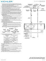
11) Instrucciones de conexión a tierra solamente para los
Estados Unidos. (Vea la ilustracion A o B).
A) En las lámparas que tienen el fleje, de montaje con un
agujero y dos hoyue los realzados. Enrollar el alambre a
tierra de la caja tomacorriente alrededor del tornillo verde y
pasarlo por el aquiero.
B) En las lámparas con una arandela acopada. Fijar el
alambre a tierra de la caja tomacorriente del ajo de la
arandela acoada y tornillo verde, y paser por el fleje de
montaje.
Si la lámpara viene con alambre a tierra. Conecter el
alambre a tierra de la lámpara al alambre a tierra de la caja
tomacorriente con un conector de alambres (no incluido)
espués de seguir los pasos anteriores. Nunca conectar el
alambra a tierra a los alambres eléctros negro o blanco.
12) Haga les conexiones de los alambres (no se proveen los
connectores.) La tabla de referencia de abajo indica las
conexiones correctas y los alambres correspondientes.
Date Issued: 8/29/14
IS-43641-US
ARANDELA
CONCAVA
A
B
TIERRA DE LA
CAJA DE SALIDA
TORNILLO DE TIERRA,
VERDE
DEPRESIONES
TIERRA
ARTEFACTO
CONECTOR DE ALAMBRE
(NO SE PROVEE)
TIERRA DE LA
CAJA DE SALIDA
TORNILLO DE TIERRA,
VERDE
TIERRA
ARTEFACTO
Conectar el alambre de
suministro negro o rojo al
Conectar el alambre de
suministro blanco al
Negro Blanco
*Cordon paralelo (redondo y liso)
*Cordon paralelo (cuadrado y estriado)
Claro, marrón, amarillio o negro
sin hebra identificadora
Claro, marrón, amarillio o negro
con hebra identificadora
Alambre aislado (diferente del verde)
con conductor de cobre
Alambre aislado (diferente del
verde) con conductor de plata
*Nota: Cuando se utiliza alambre paralelo
(SPT I y SPT II). El alambre neutro es de forma
cuadrada o estriada y el otro alambre será de
forma redonda o lisa. (Vea la ilustracíón).
Hilo Neutral
SEE OTHER SIDE FOR ENGLISH TRANSLATIONS.
VEA EL OTRO LADO DE TRADUCCIONES AL INGLÉS.
We’re here to help 866-558-5706
Hrs: M-F 9am to 5pm EST
CONSULTE AL ARTEFACTO DE DIBUJO EN EL
DORSO.
-
 1
1
-
 2
2


Kichler Lighting 43641NIL18 User manual
- Type
- User manual
Ask a question and I''ll find the answer in the document
Finding information in a document is now easier with AI
in other languages
Related papers
-
Kichler Lighting 43436AUB User manual
-
 Kichler Lighting 43787PN User manual
-
 Kichler Lighting 43581AVI User manual
-
 Kichler Lighting 49475RZ User manual
-
 Kichler Lighting 49474RZ User manual
-
 Kichler Lighting 43748OZ User manual
-
 Kichler Lighting 9886TZ User manual
-
 Kichler Lighting 3502NI User manual
-
 Kichler Lighting 43755AUB User manual
-
 Kichler Lighting 43774AVI User manual


Other documents
-
Kichler 42399AP Operating instructions
-
-
-
-
-
-
-
-
Kichler 49743WZCL18 Installation guide
-