Page is loading ...

CAUTION!
All accessories, switches, climate
controls panels, and especially air bag indicator
lights must be connected before cycling the
ignition. Also, do not remove the factory radio
with the key in the on position, or while the
vehicle is running.
Metra. The World’s Best Kits.
®
MetraOnline.com © COPYRIGHT 2018 METRA ELECTRONICS CORPORATION REV. 6/29/18 INST99-8227
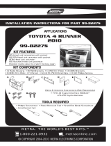
INSTALLATION INSTRUCTIONS
99-8227
U.S. Patent # D639,292
KIT FEATURES
• DIN radio provision with pocket
• ISO DIN radio provision with pocket
• ISO DDIN radio provision
99-8227S - Painted in silver
99-8227CHG - Finished in charcoal high gloss
KIT COMPONENTS
• A) Radio Housing • B) ISO brackets • C) ISO trim plate • D) ISO DDIN brackets • E) ISO DDIN trim plate • F) Pocket • G) (4) PC-7503 Panel Clips
• H) (2) Phillips Screws
TOOLS REQUIRED
• Phillips screwdriver • Panel removal tool
• 10mm socket wrench • Cutting tool
TABLE OF CONTENTS
Dash Disassembly ...............................................2-3
Kit Preparation .......................................................4
Kit Assembly
–DIN radio provision with pocket ........................5
–ISO DIN radio provision with pocket ..................6
–ISO DDIN radio provision .....................................7
WIRING & ANTENNA CONNECTIONS
(sold separately)
Wiring Harness: 70-1761 (w/o amp) • TYTO-01 (10-13)
• TYTO-01 (14-up*)
Antenna Adapter: Not required 10-13 • 40-LX11 (14-up*)
Steering wheel control interface :ASWC-1
A
G H
B C D E F
Toyota 4-Runner 2010-up*
*Visit MetraOnline.com for up-to-date vehicle specific applications.

1.800.221.0932
|
MetraOnline.com
2
1. Unclip and remove the (2) climate
control knob trim panels. (Figure A)
2. Unclip and remove the climate control
(Figure B)
3. Remove (4) 10mm bolts securing the
radio. (Figure C)
Continued on the next page
(Figure B)
(Figure A) (Figure C)
DASH DISASSEMBLY

REV. 6/29/2018 INST99-8227
3
DASH DISASSEMBLY
(CONT.)
4. Unclip and remove the vents from the
factory radio panel. (Figure D)
5. Remove the (2) Phillips screws securing
the trim panel on the top of the factory
radio panel. (Figure E)
6. Remove the (4) Phillips screws securing
the outer a/c vent control wheel trim
pieces. (Figure F)
7. Unclip and remove the hazard switch
from the factory radio trim panel.
(Figure G)
Continue to Kit Preparation
(Figure D)
(Figure F)(Figure E)
(Figure G)

1.800.221.0932
|
MetraOnline.com
4
(Figure B) (Figure D)
(Figure A) (Figure C)
1. Attach the outer a/c vent control wheel
trim pieces to the radio housing using
the factory hardware. (Figure A)
2. Attach the trim panel to the top of
the radio housing using the factory
hardware. (Figure B)
Note: 2 screws are provided “Just in
case”.
3. Attach the a/c vents to the radio
housing. (Figure C)
4. Snap the hazard switch into the radio
housing. (Figure D)
5. Attach (4) panel clips to the radio
housing. (Figure D)
Continue to Kit Assembly
KIT PREPARATION

REV. 6/29/2018 INST99-8227
5
DIN radio provision with pocket
1. Remove the metal DIN sleeve from the
aftermarket radio.
2. Slide the DIN sleeve into the top opening
the
radio housing
and secure by bending
the metal locking tabs down. (Figure A)
3. Snap the
pocket
into the bottom
opening of the
radio housing
. (Figure B)
4. Slide the radio back into the sleeve until
it clicks in. (Figure C)
5. Locate the factory wiring harness in
the dash. Metra recommends using
the proper mating adapter from Metra
or AXXESS. Test the radio for proper
operation.
6. Reassemble the dash in reverse order of
disassembly.
(Figure A)
(Figure C)(Figure B)
KIT ASSEMBLY

1.800.221.0932
|
MetraOnline.com
6
ISO DIN radio provision with pocket
1. Remove the metal DIN sleeve and trim
ring from the aftermarket radio.
3. Secure the
ISO Brackets
to the radio
with the screws supplied with the radio.
(Figure A)
4. Snap the
pocket
into the bottom
opening of the
radio housing
. (Figure B)
5. Slide the radio/bracket assembly into
the top opening of the
radio housing
until the side clips engage. (Figure C)
6. Snap the
trim plate
into the
radio
housing
. (Figure C)
7. Locate the factory wiring harness in
the dash. Metra recommends using
the proper mating adapter from Metra
or AXXESS. Test the radio for proper
operation.
7. Reassemble the dash in reverse order of
disassembly.
KIT ASSEMBLY
(Figure A)
(Figure C)(Figure B)

REV. 6/29/2018 INST99-8227
7
KIT ASSEMBLY
ISO DDIN radio provision
1. Cut and remove the center bar from the
radio housing
. (Figure A)
2. Snap the
ISO DDIN brackets
to the
inside edge of the
radio housing
.
(Figure B)
3. Slide the radio into the
radio housing
,
then secure the radio using the screws
supplied with the radio. (Figure C)
4. Snap the
ISO DDIN trim plate
into the
radio housing
. (Figure C)
5. Locate the factory wiring harness in
the dash. Metra recommends using
the proper mating adapter from Metra
or AXXESS. Test the radio for proper
operation.
6. Reassemble the dash in reverse order of
disassembly.
(Figure A)
(Figure C)(Figure B)

KNOWLEDGE IS POWER
Enhance your installation and fabrication skills by
enrolling in the most recognized and respected
mobile electronics school in our industry.
Log onto www.installerinstitute.com or call
800-354-6782 for more information and take steps
toward a better tomorrow.
®
Metra recommends MECP
certified technicians
IMPORTANT
If you are having difficulties with the installation of this product,
please call our Tech Support line at 1-800-253-TECH. Before
doing so, look over the instructions a second time, and make
sure the installation was performed exactly as the instructions
are stated. Please have the vehicle apart and ready to perform
troubleshooting steps before calling.
Metra. The World’s Best Kits.
®
MetraOnline.com © COPYRIGHT 2018 METRA ELECTRONICS CORPORATION REV. 6/29/18 INST99-8227
INSTALLATION INSTRUCTIONS
99-8227
/